Week 3 Challenge : CFD meshing on Turbocharger
Aim
To correct the geometry error mesh the surface at the given criteria and assign the PIDs to create the volume of the turbocharger.
Objective
Check the given model for geometric errors to create a surface mesh with specified target lengths according to PIDs.
- Blade stage 1 = 1 mm
- Blade stage 2 = 1 mm
- Impeller = 2 mm
- Shaft rotor = 1 mm
- Turbo casing = 5 mm
- Compressor casing = 5 mm
- Inlet casing cover = 5 mm
To perform volumetric mesh for the required volumes.
Procedure
For the given model, to check the geometry error assign PIDs to the surface mesh with the given data and volumetric mesh of the model are step-by-step detail explained as below.
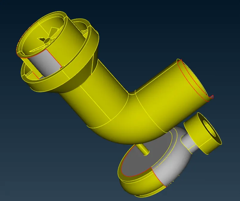
1. Open the given file in ANSA, to select the model Face -> Orient -> Auto -> yellow outside volume and check the model in the checks manager as shown in the image below.
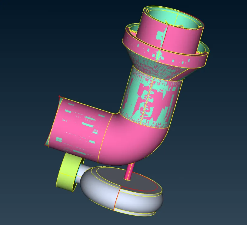
2. To change the Draw mode ENT to PID, it shows the overlapping surface on the model. That surface carefully selected delete using the Menubar-> delete option, after deleting the overlapping surface it made some material loss in the model as shown in below.
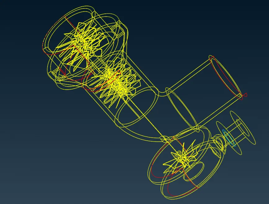
3. in the single cons areas are filled on the surface by the Coons and Fill hole option, Face -> New -> Coons and another are cons -> Fill hole to select the single cons and create a surface of the given model as shown in the image.
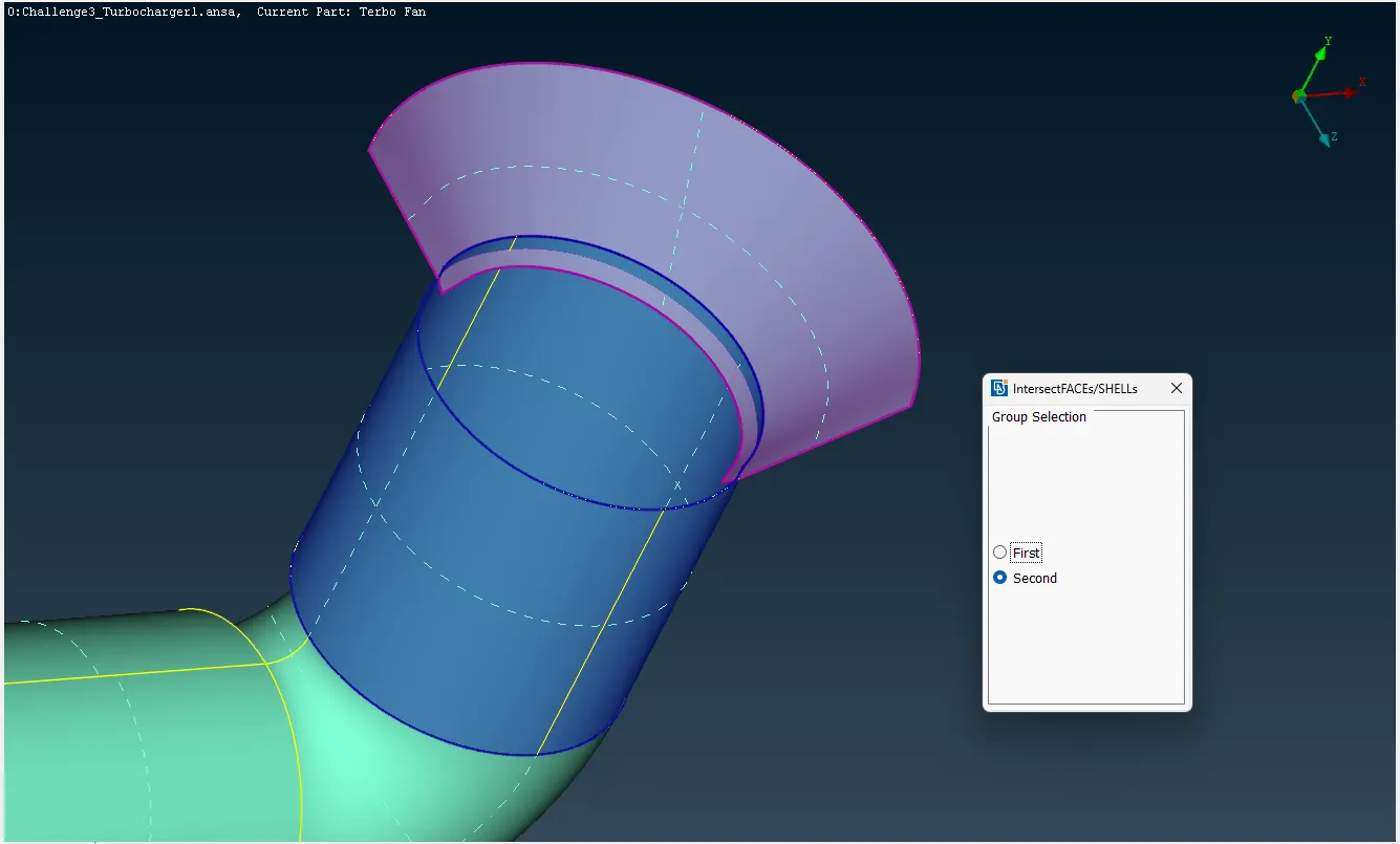
4. In the model have intersected regions to clear and delete the remaining surface by the option Face -> Intersect -> select the first surface and select the second surface -> to middle click can intersect each other, and remaining unwanted surfaces are deleted as shown below.
5. The Blade Stages 1 and 2, The Impeller and shaft rotor are given separate parts. The parts have faces in the centre hollow through the shaft to select unwanted surfaces that are deleted as shown below.
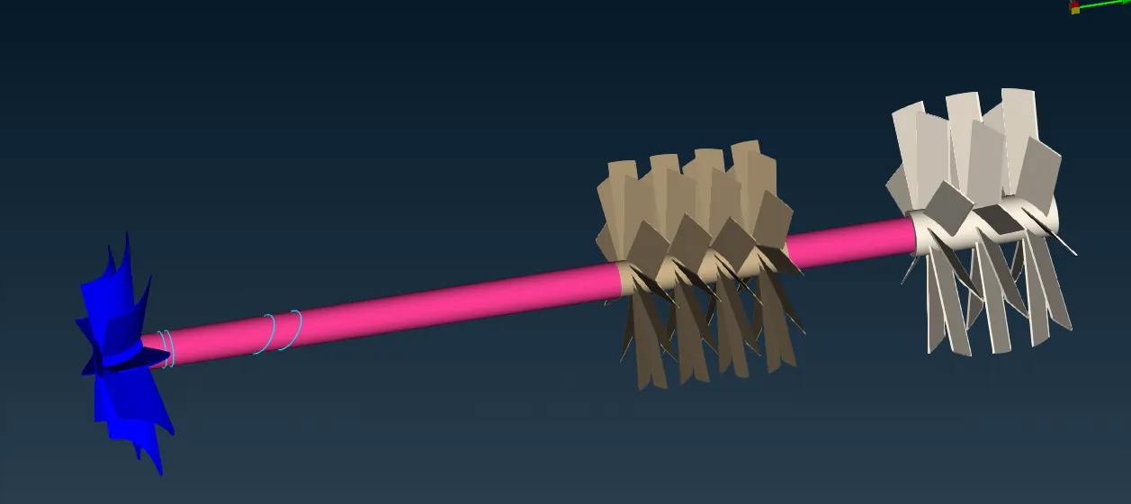
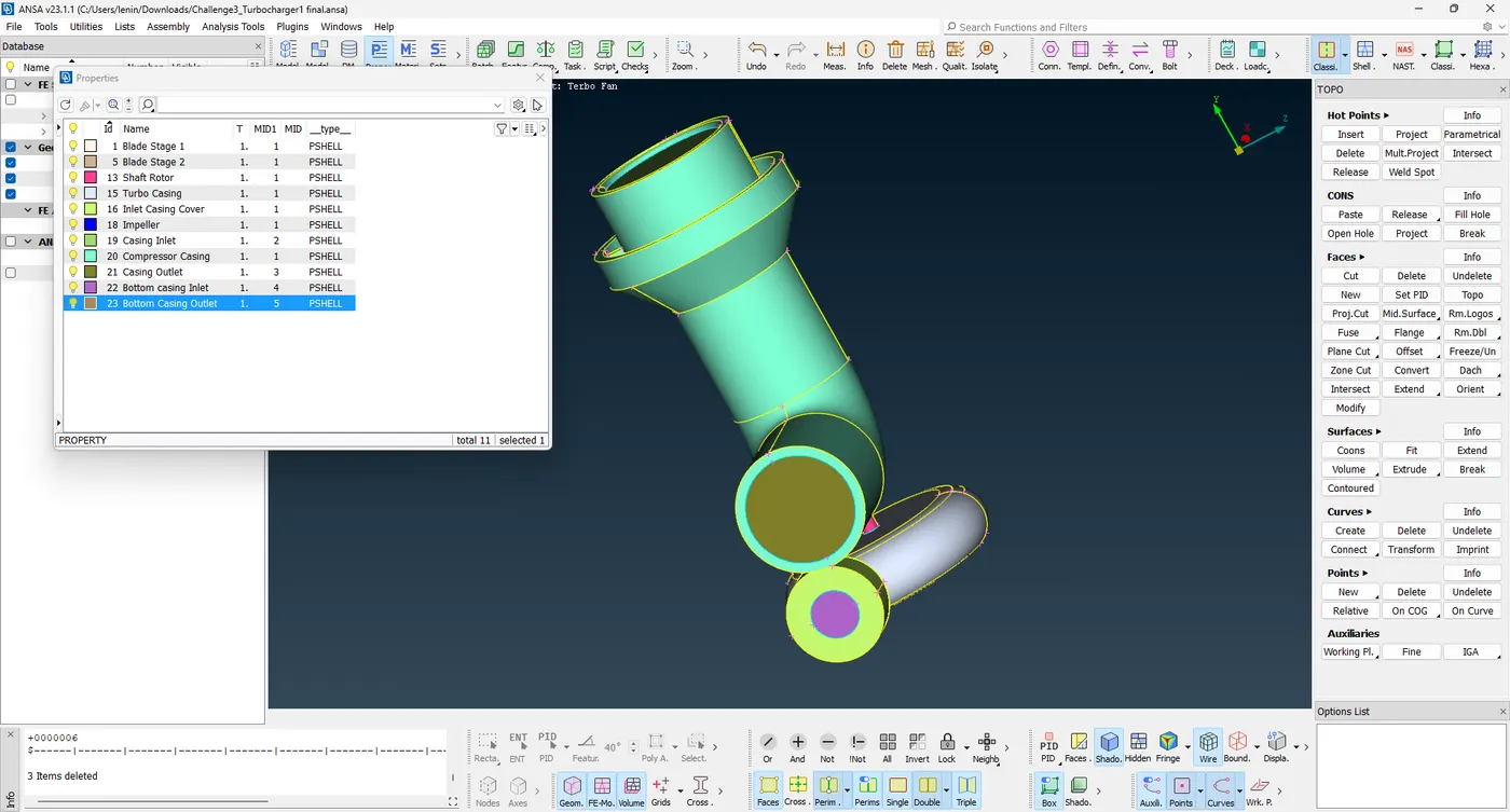
6. After correcting the geometry error and creating the surface on the inlet and outlet of the Compressor casing and Turbo casing. Assign the PIDs to the respective surfaces as shown in the image below.
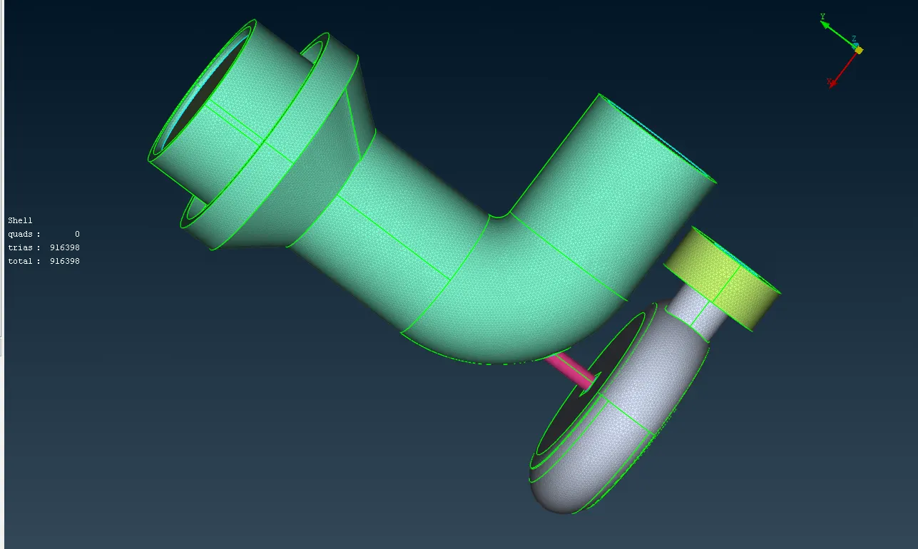
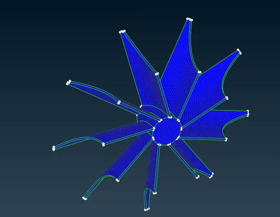
7. To create the surface mesh after the PIDs are assigned at the given target length as following are
- Blade stage 1 = 1 mm
- Blade stage 2 = 1 mm
- Impeller = 2 mm
- Shaft rotor = 1 mm
- Turbo casing = 5 mm
- Compressor casing = 5 mm
- Inlet casing cover = 5 mm
To mesh the surface at the given quality criteria as shown in the image below.
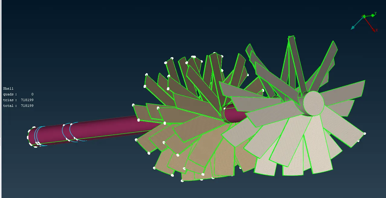
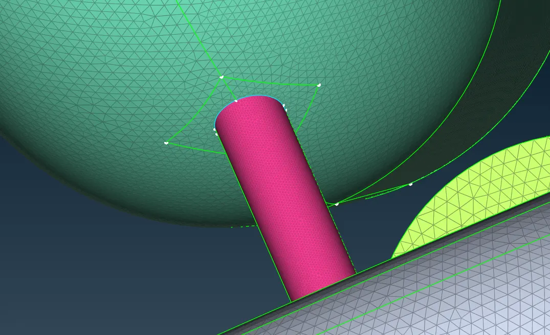
8. Goto Volume Mesh to create the volumetric mesh of the turbocharger Volume mesh -> Define -> Whole Model -> Ok. After the automatically assign some region. In that select need volume and others are deleted as shown below.
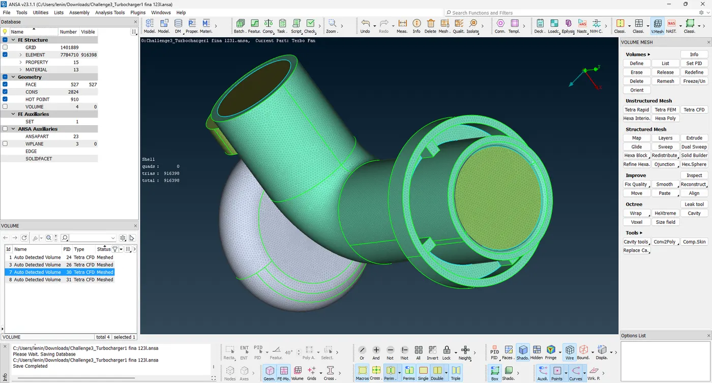
After creating the volume PIDs select the volume and remesh the volume in the Tetra CFD Mesh, one by one this process because it takes some time in larger volumes.
These are the steps to create the volumetric mesh in the given model.
Learn Outcomes
In this challenge to learned how to the volumetric mesh of models and learned about some new tools like Intersect, Release, Topo, Fine, cut etc.
Result
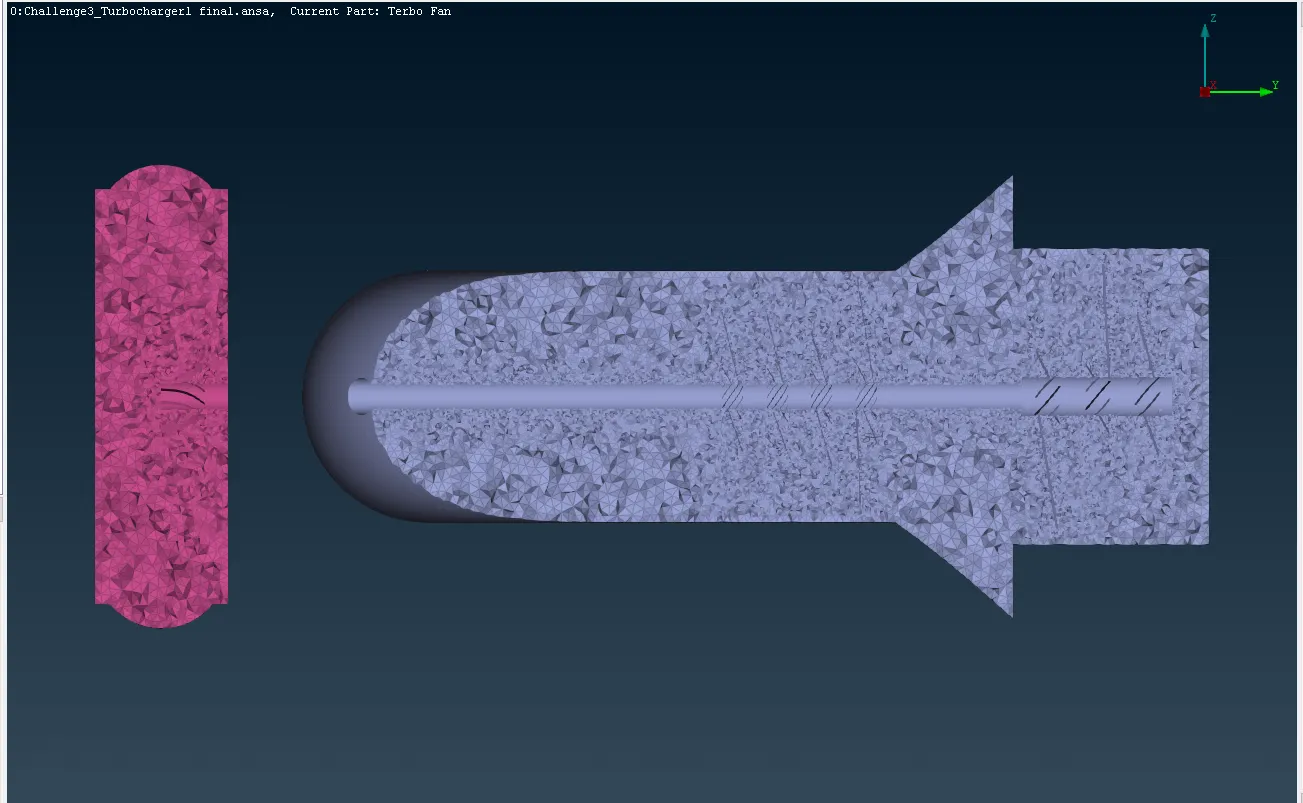
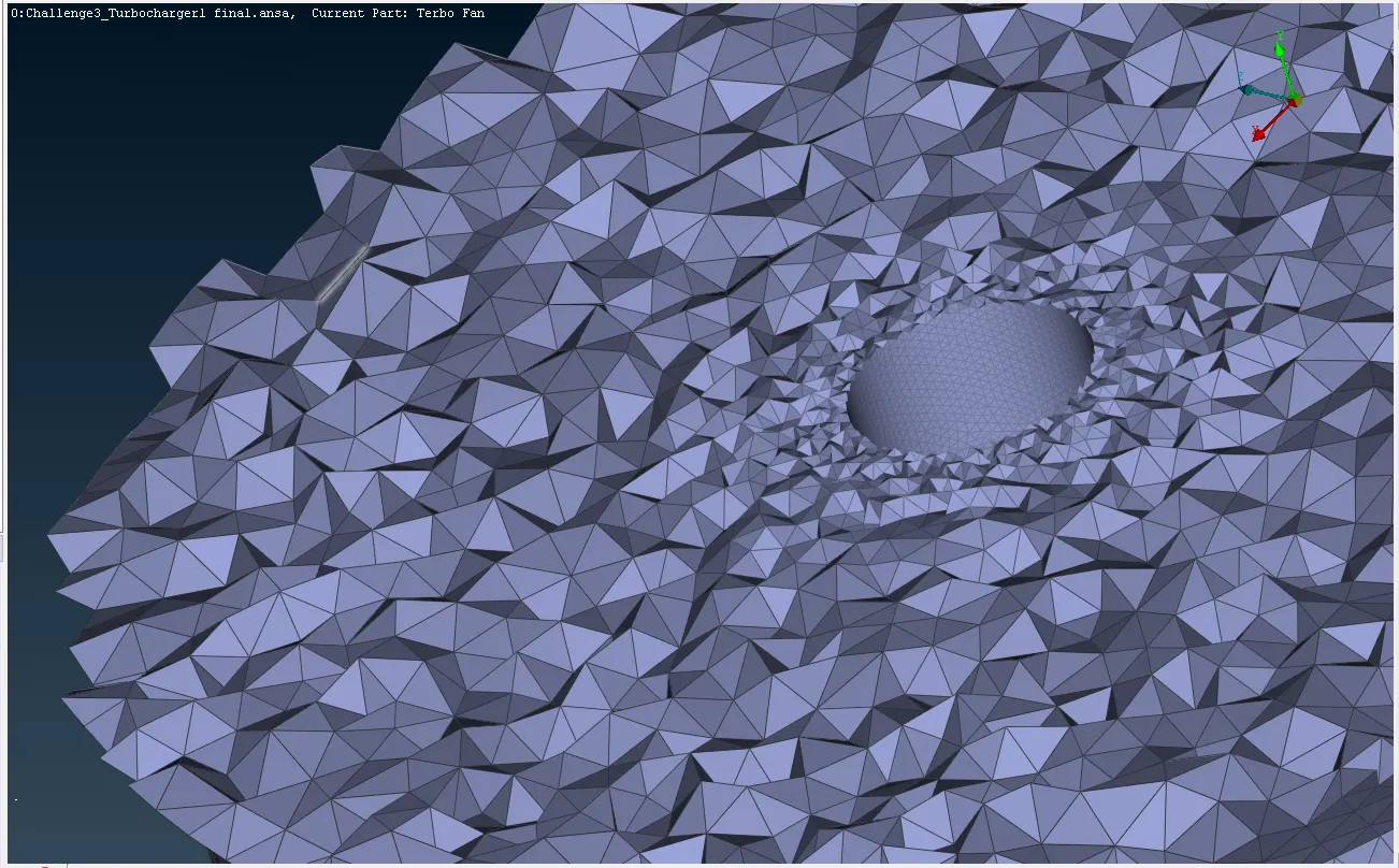
To solve the given model successfully at the given quality criteria as shown in the images below.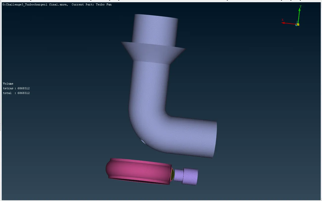
Conclusion
The given model is a volumetric meshed at Tetra CFD in 6868312 tetrahedral elements mesh the Turbocharger.
The Turbocharger is successfully meshed, volumetric meshed by using ANSA. The model link attached below.