Week 3 Challenge : CFD meshing on Turbocharger
Given model is
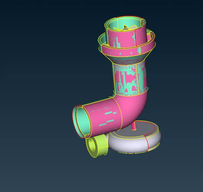
First, we need perform geometry checks for any errors.
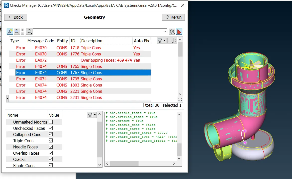
From the above, it can be seen that there are a total of 30 errors most of them being single CONS.
But before that, from the given model, it is observed that there are a lot of glitches or inconsistent colour pattern along the surfaces.
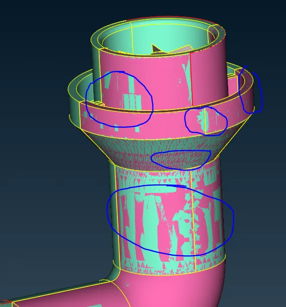
These occur becasue of overlapped surfaces i.e., multiple surfaces on one another stacked.
These are big errors and needs to be resolved.
First, the big pink surace overlapping with the main green surface needs to be deleted.
For doing this in an easy way, select the NOT option in the boolean operation and next select the PID region.
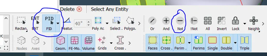
Then select the green PID. By doing this, the green PID region is hidden and the overalapped pink surface is visible and can be deleted easily.
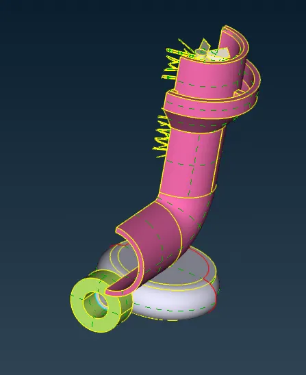
Now, delete the pink surface and select ALL to view the hidden PIDs.
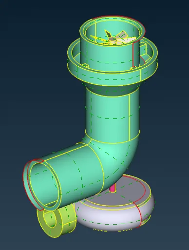
Now, single CONS can be converted to double CONS.
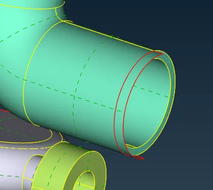
It can be seen that there is a protruded surface to the outside and it alone cannot be deleted as it is a part of whole entity.
So, delete the whole entity and create a new face in place of that.
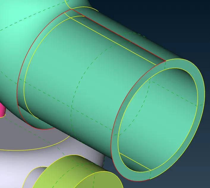
After deleting, 4 new single CONS are created and this can be converted to double CONS using Fill Hole command.
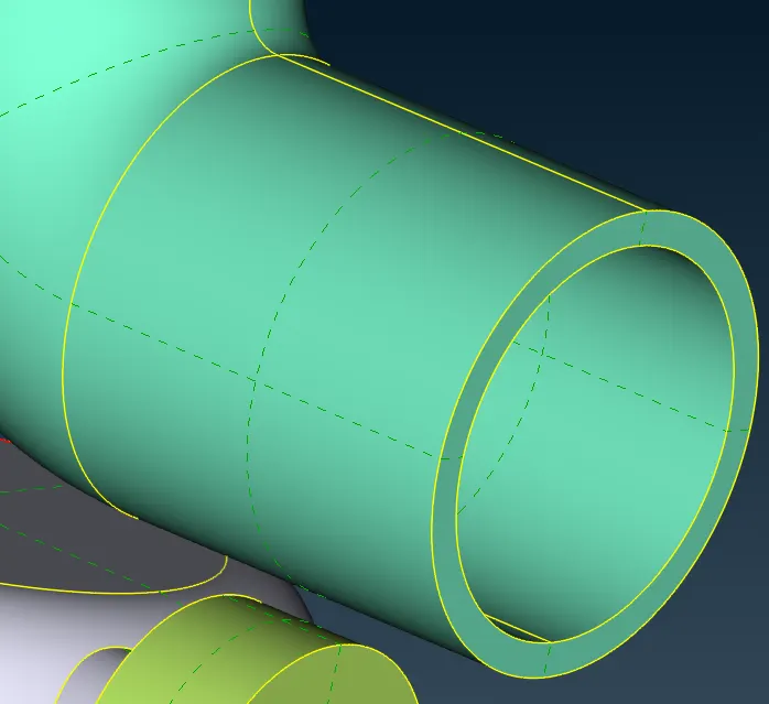
Now, single CONS at the top of component needs to fixed as seen below
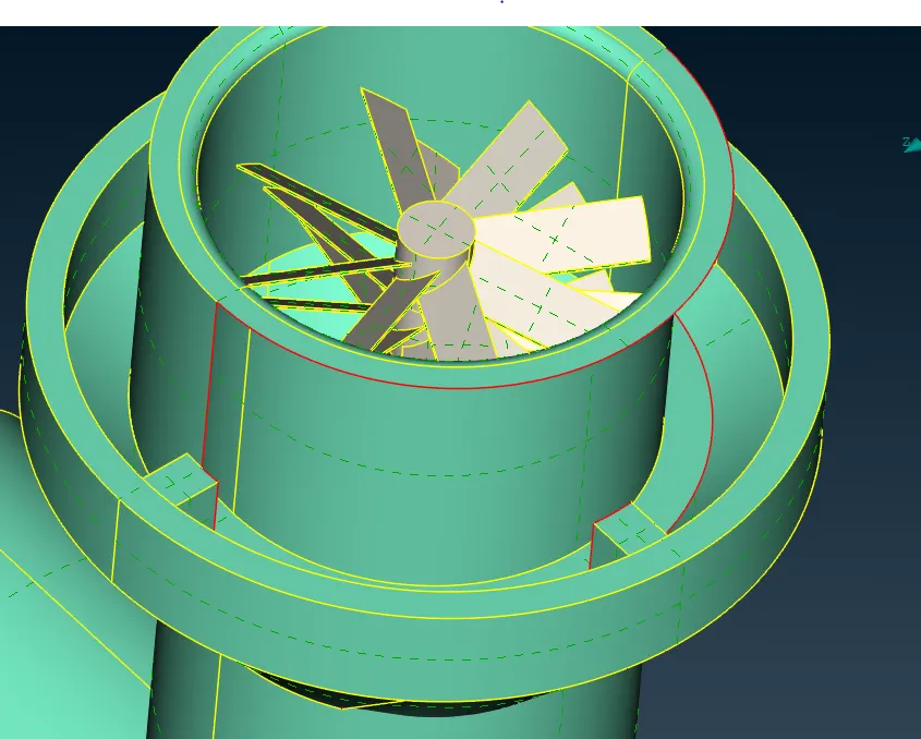
These kind of multiple single CONS in a single area needs to be dealt carefully.
Creating a new face using loop option mignt not result in desired surfaces even though all the single CONS are converted to double CONS.
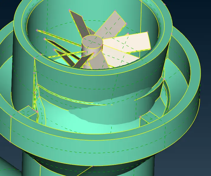
By using loop option to create new face, it is seen that the output face is not proper.
In this case, divide the overall area into small segments and craete new faces individually for these smaller segments.
For this, one of the methods is to project the hot points at the bottom onto the bigger single CON at the top.
By doing this, the big single CON is divided.
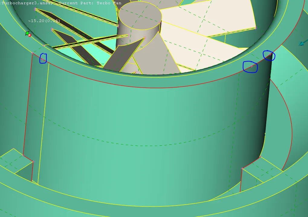
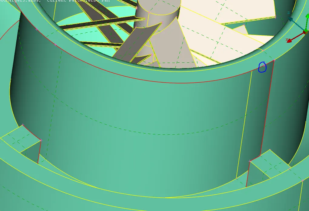
Now, select the single CONS by entity and craete a new face.
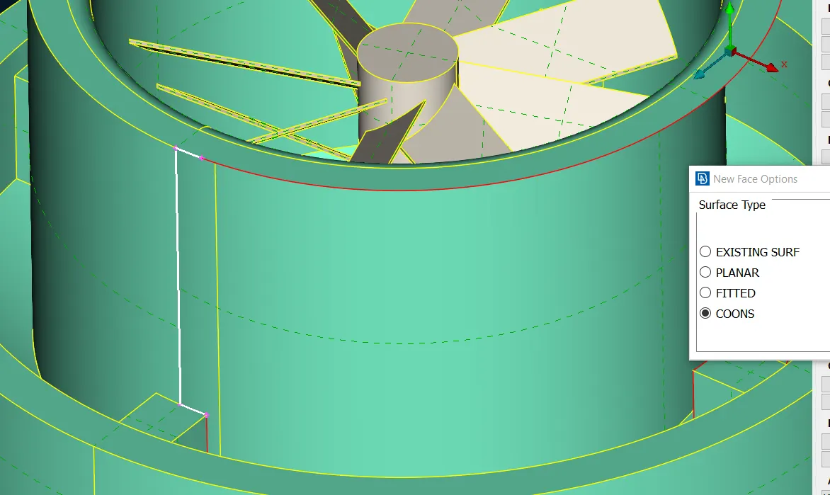
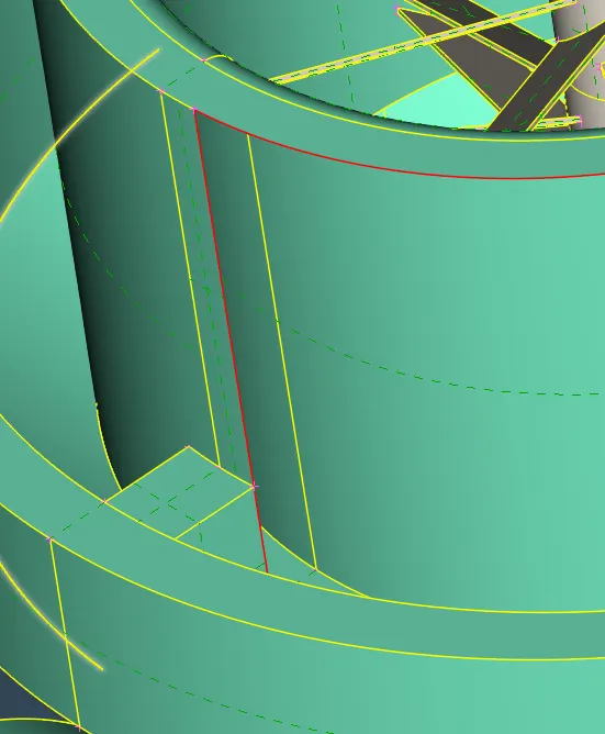
A new face is created in that smaller segment.
Similarly, it is done for other segments.
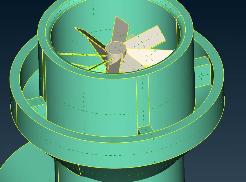
All the single CONS are now converted to double CONS as seen in above image.
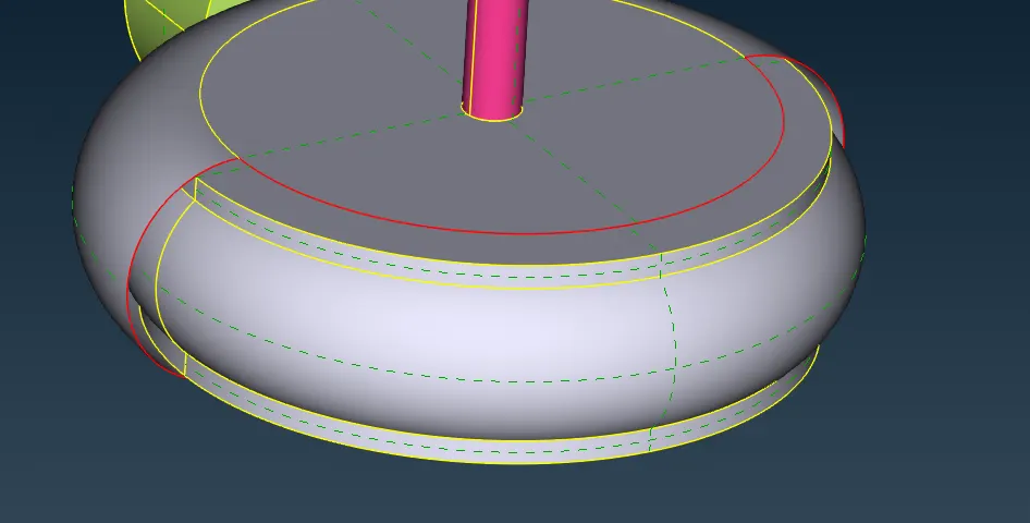
Similar steps as above are followed to fix the single CONS in above image.
Multiple hot points are created on the curves and double CONS are created in a segmental method.
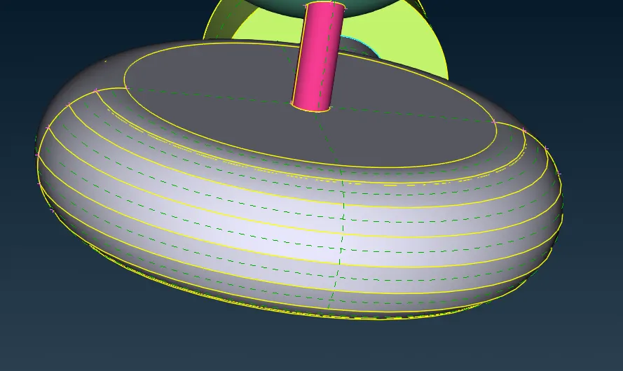
Check for other single CONS in the assembly by performing geometry checks.
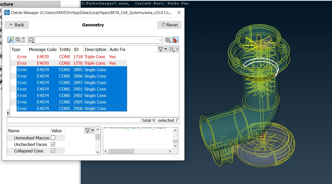
It can be seen there are 7 single CONS and 2 triple CONS.
First, convert all the single CONS into double CONS as did above.
In order to see the single CONS clearly, hide some of the surfaces using NOT option and hide some of the components.
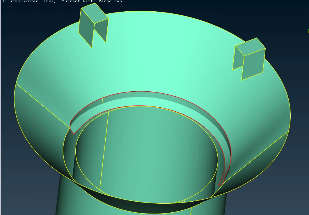
From the above picture, it can be seen that two surfaces are intersected resulting in single CONS.
Delete the intersecting surfaces so those single CONS will disappear.
This can be done using "Intersect" option in Faces.
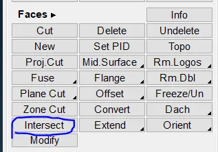
When is is selected, it asks to select the first and secind surfaces.
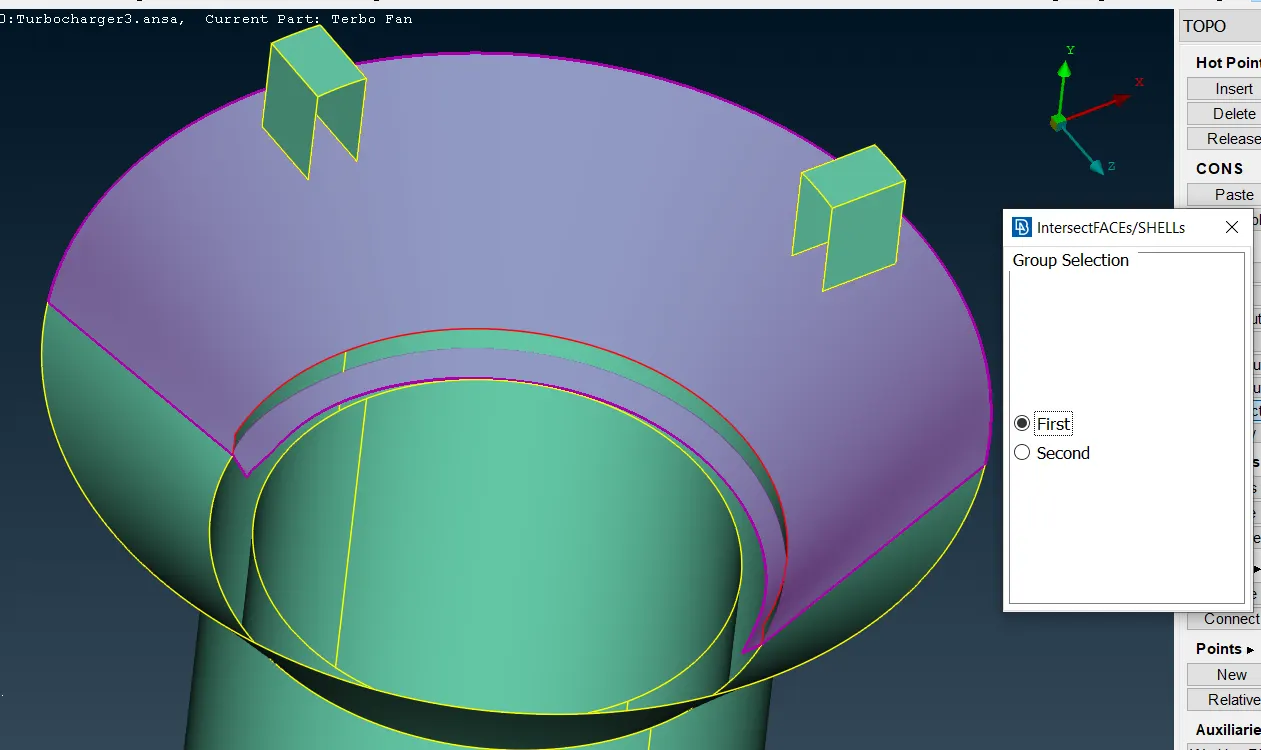
Select the first surface and do middle click and select the second surface.
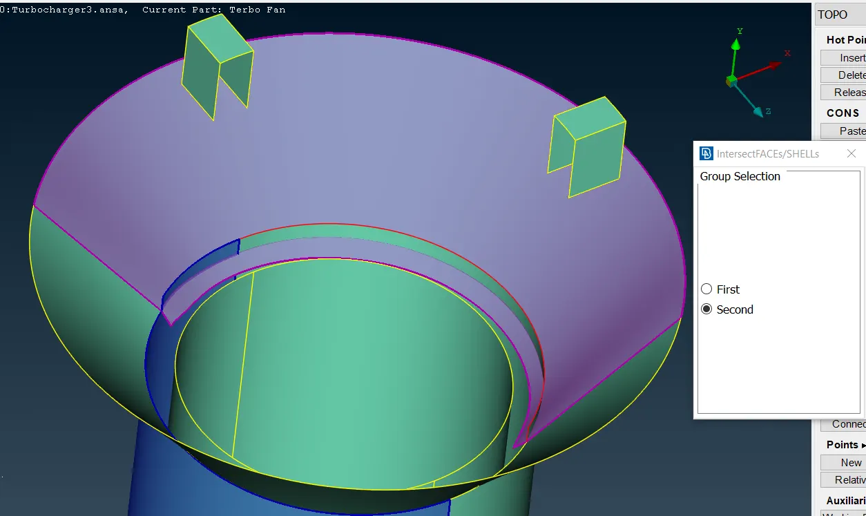
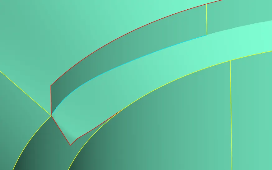
After doing that, it can be seen that the protruding surface is seperated from the parent surface and ca bn be deleted.
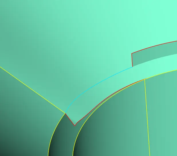
Similarly, do the same to delete other protruding surfaces.
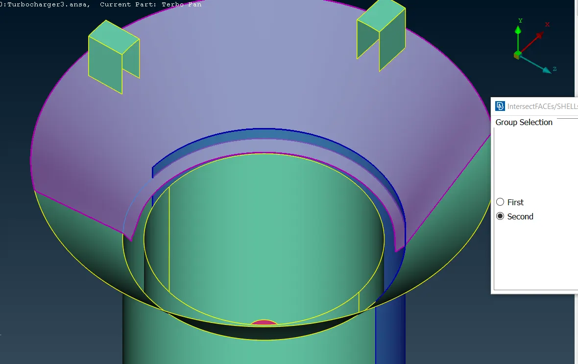
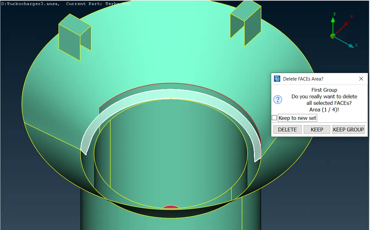
It would ask whether to delete or keep the highlighted surface.
In the above picture, the highlighted surface should be deleted.
Similarly, delete the other protruded surface.
After doing this, single CONS are converted to double CONS.
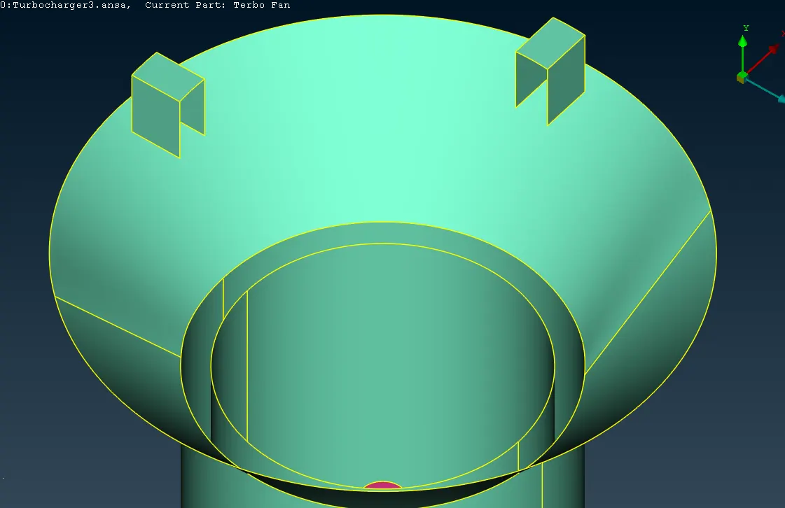
Perform geometry check and check if there are any other errors.
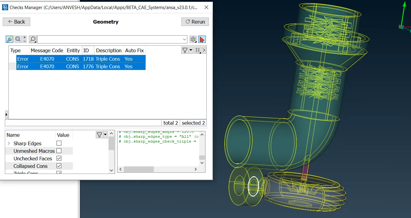
From above picture, it is seen that there are two triple CONS.
Triple CONS are not errors but proper check should be done if there are 3 surfaces that created triple CONS (or) if there are any overlapped surfaces that resulted in triple CONS.
If its the later case, those overlapped surfaces must be deleted.
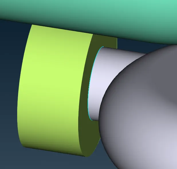
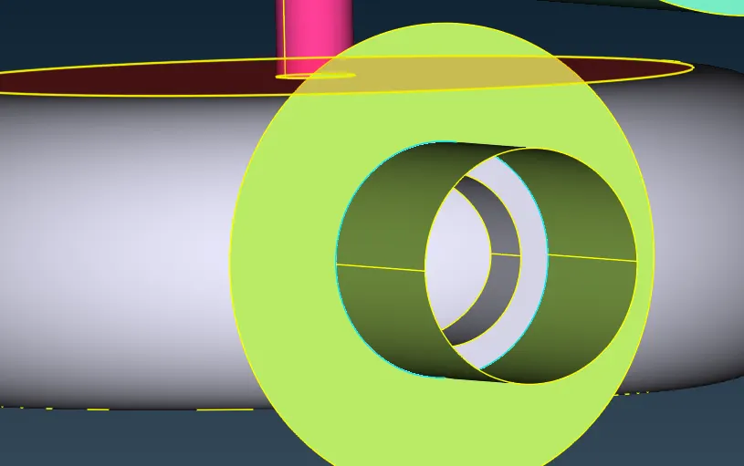
From above, it is seen that the triple CON curve is shared by 3 surfaces and therefore, its not an error.
In the overall model, check for any overlapped or unnecessary surfaces as they sometimes will not be shown as errors in geometric checks.
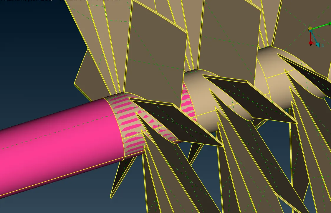
In the above picture, there is one overlapped surface. The pink surface needs to be deleted.
But when its is selected, the whole pink PID is selected instead of that overlapped part.
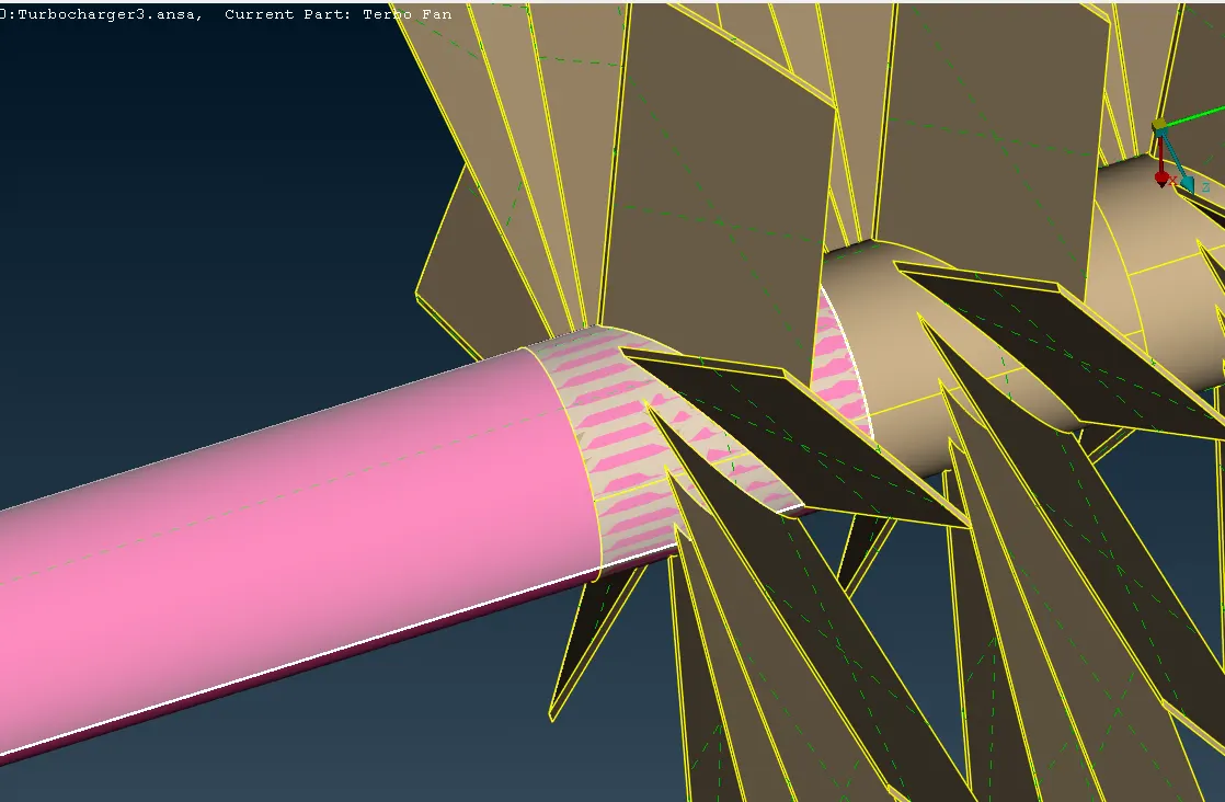
So, to delete only the ovelapped part, pink surface needs to be divided upto the overalpped section.
CONS must be created to do that.
The double CONS cna be used to project onto the end of overlapped pink surface to create new double CONS.
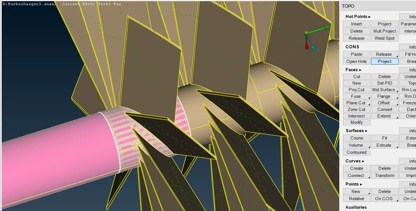
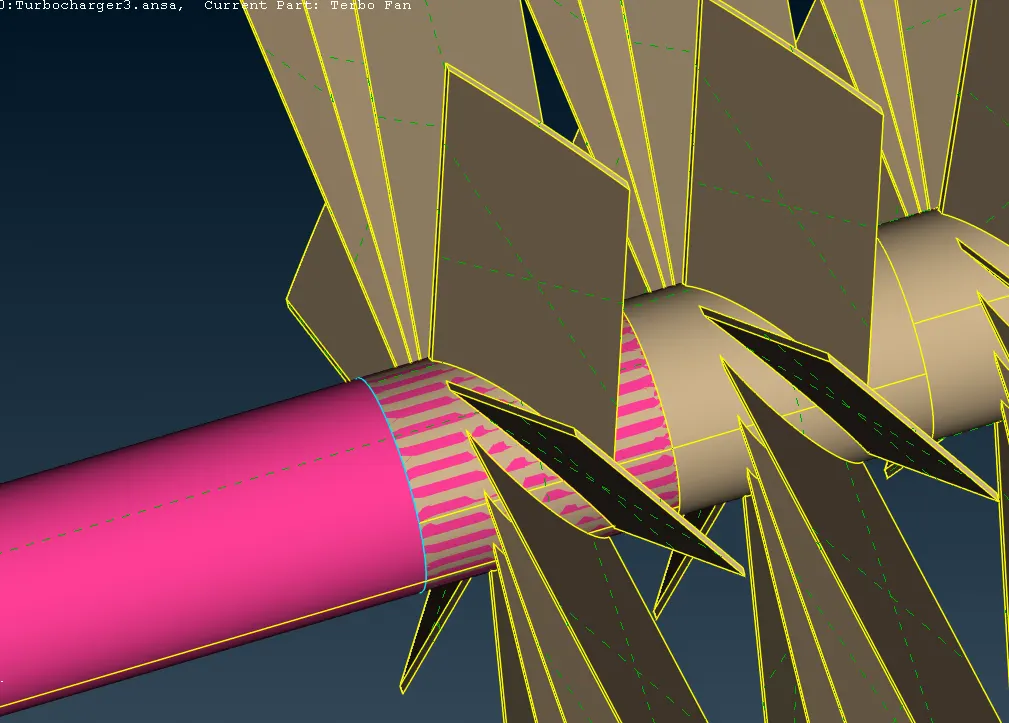
Now, a triple CON is created as there are 3 surfaces sharing the same CONs.
Now, delele the overlapped pink surface.
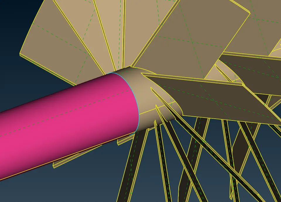
The overlapped surface is dlelted bit its seen that there's still a triple CON present.
Check for any other surfaces present. If they are necessary, keep them or delete them if unnecessary.
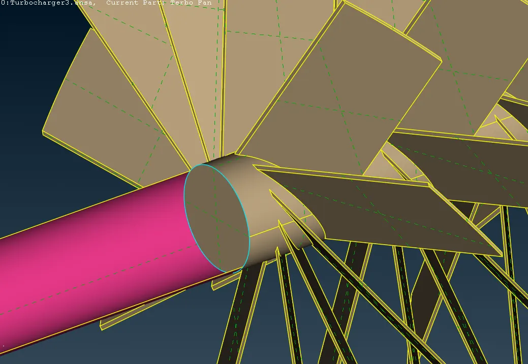
From above picture, it is seen that there is a surface inside dividing the both pink and brown surfaces.
This surface must be deleted as pink and brown surface should be continous without any blockage in between.
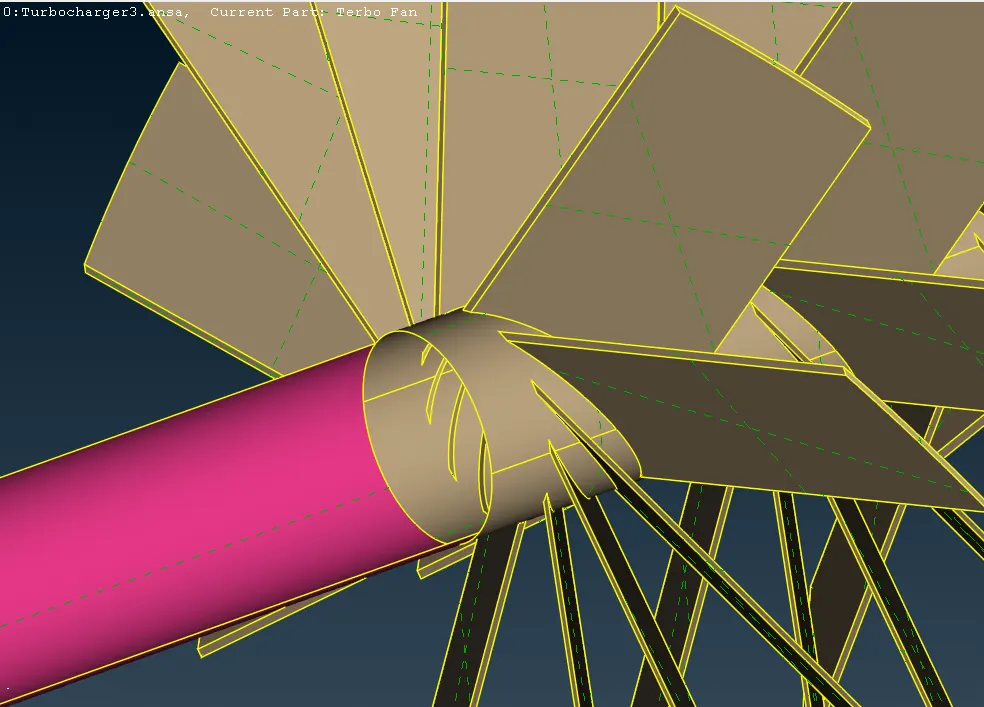
After deleting the surface, is is seen that triple CON is now converted to double CON.
Similarly, check if there are any other surfaces like these and delete them.
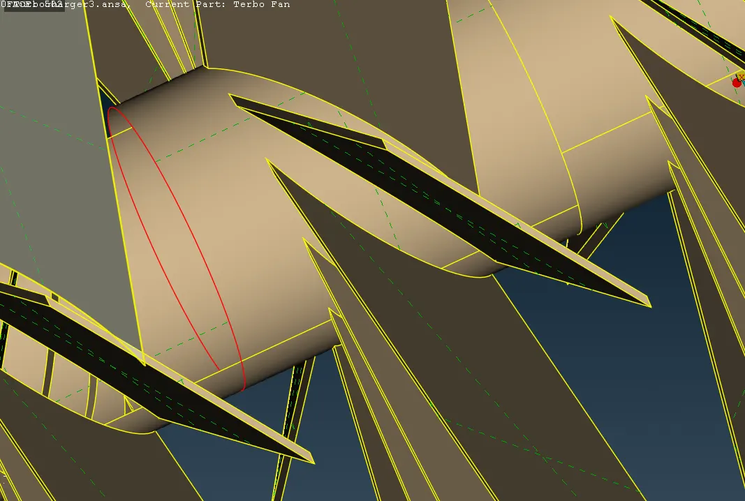
While removing unnecessary surfaces, single CONS may arise due to deletion.
These must be converted to double CONs.
This can be done using Topo option.
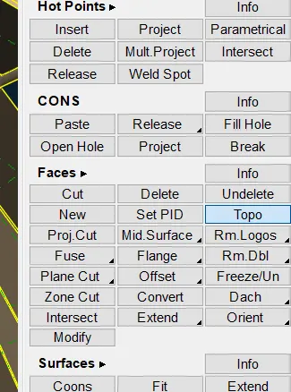
This option converts single to double CONS & double to triple CONS.
Double click on the single CONS and do middle click outside. They will be converted to double CONS.
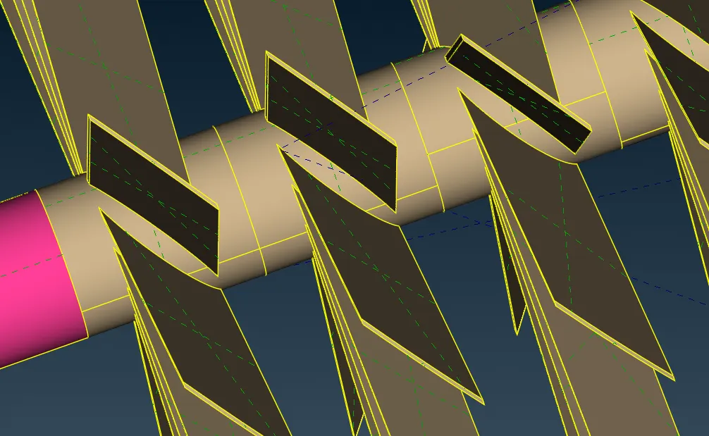
Similarly, do for the surfaces if any.
Also, is it observed that pink and blue componensta re seperated by a surface.
In reality, there should not be any surface seperating them. The blue circular surface should be deleted.
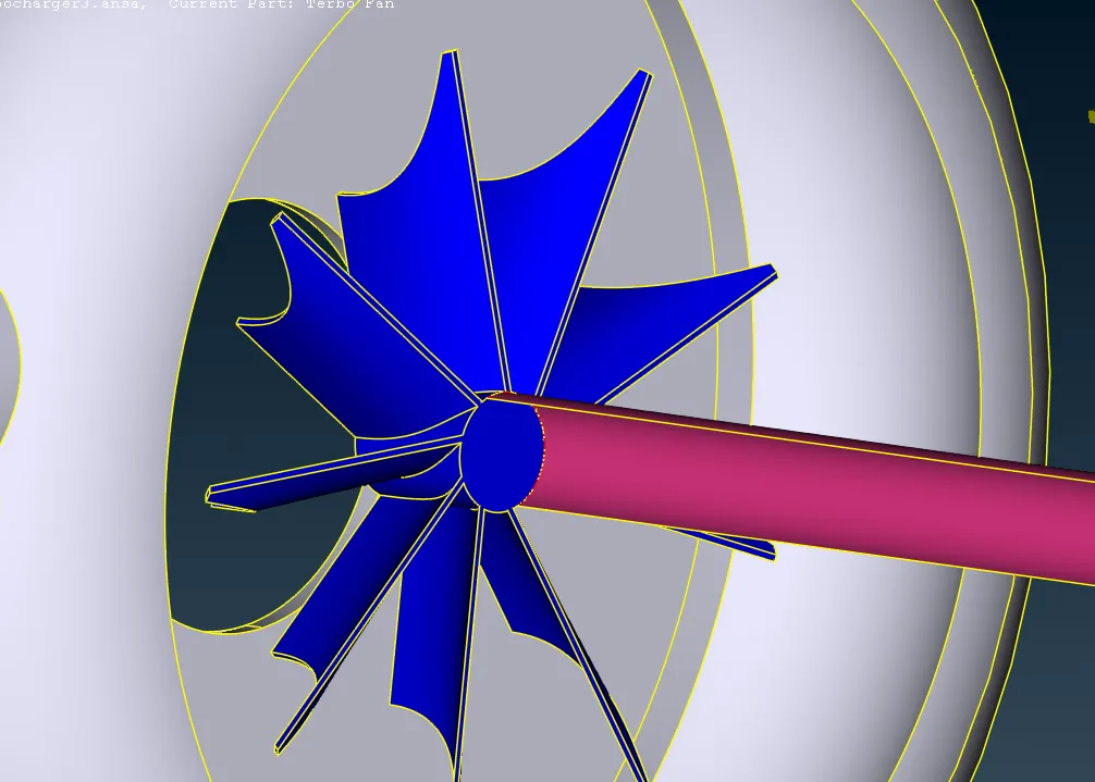
But when trying to delete that, other protruded surfaces along with the circular surface are getting selected.
Both are one surface. Those two surfaces must be divided into two individual surfaces so that only the circular surface gets selected.
In order to do that, a new double CON must be created on the circular surface.
For that, double CON on pink surface is projected on the blue circular surface using "Project" option in CONS.
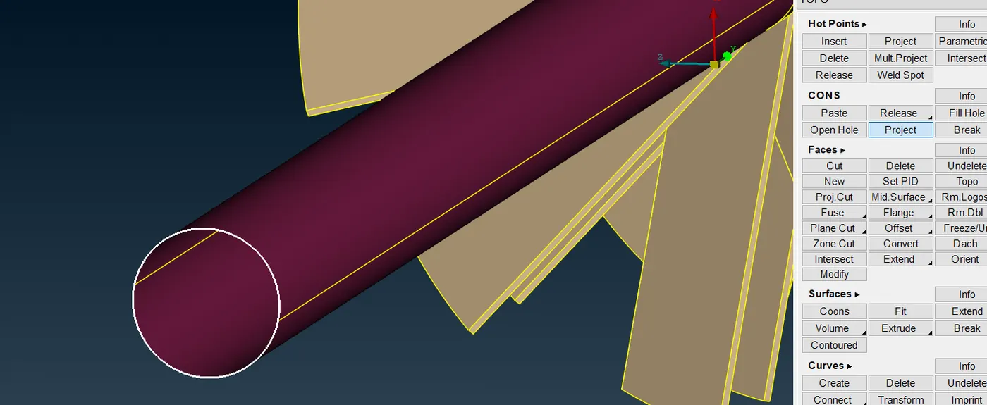
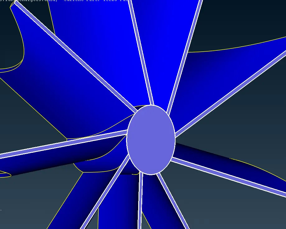
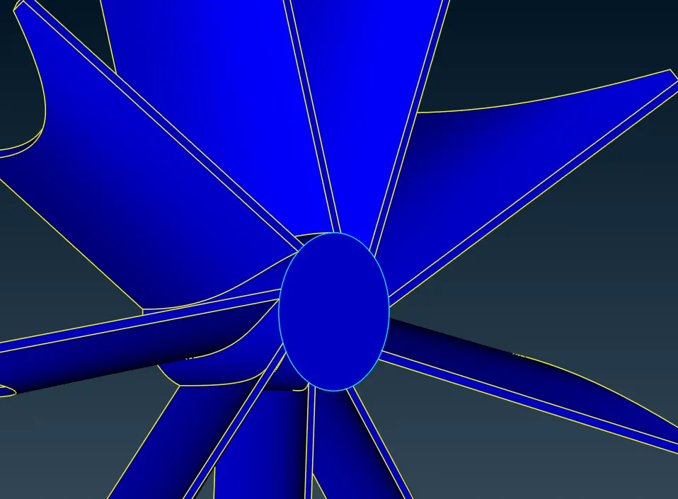
From the above, it is seen that a new CON is created on the circular surface and now the surface can be deleted.
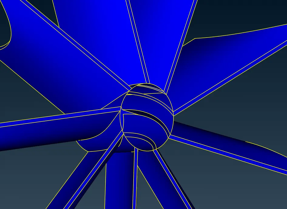
After the topo cleanup is completed, close all the open surfaces as below in order to do meshing
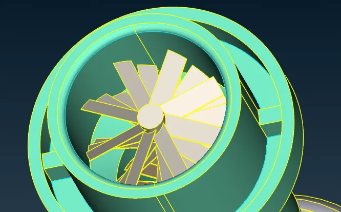
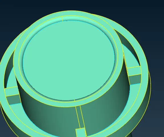
Similarly, do it for other open surfaces.
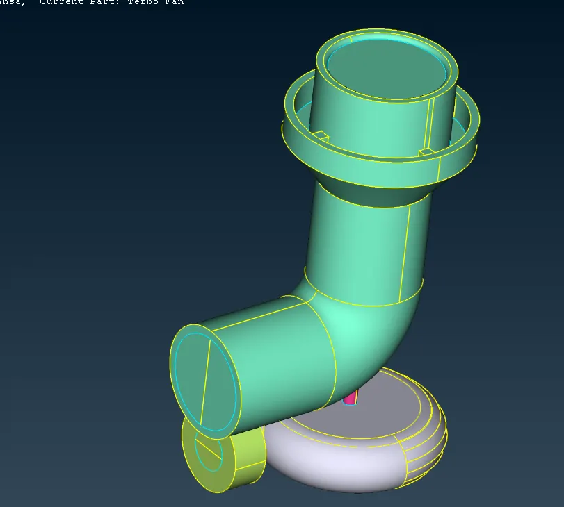
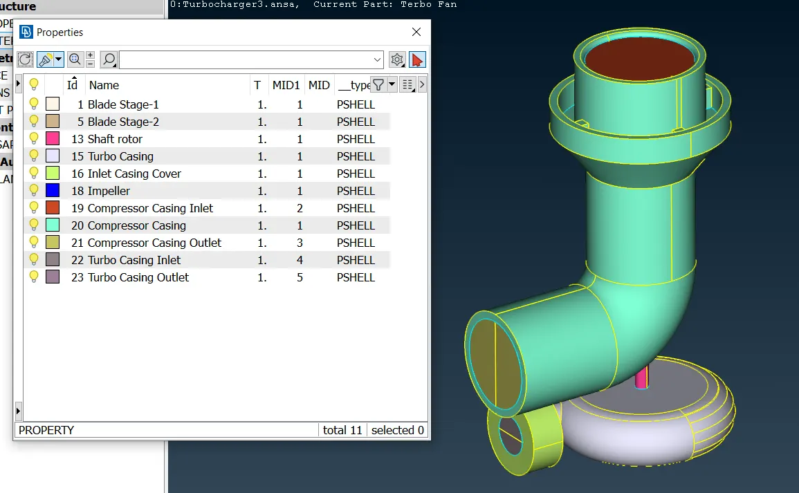
The next step is to create and assign PIDs.
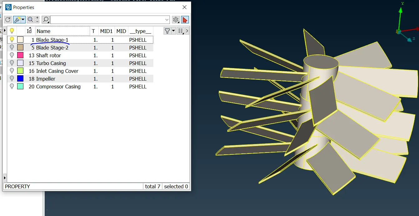
PID 1 - Blade Stage 1
Create a PID named Blade Stage 1 and assign as below
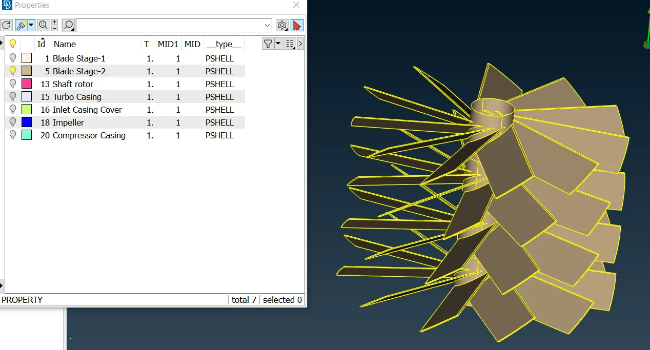
PID 2 - Blade Stage 2
Create a PID named Blade Stage 2 and assign the blades below the Blade Stage 1 to it.
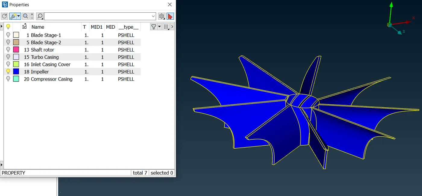
PID 3 - Impeller
Create a PID named Impeller and assign the bottom most blades to it.
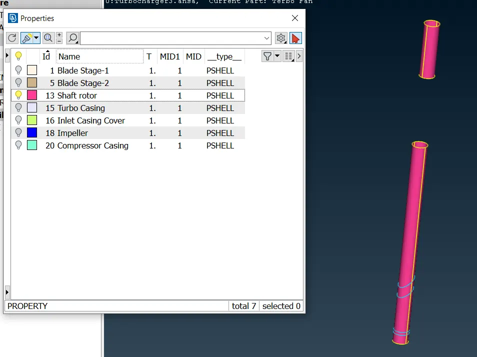
PID 4 - Shaft rotor
Create a PID named SHaft rotor and assign the shaft to it.
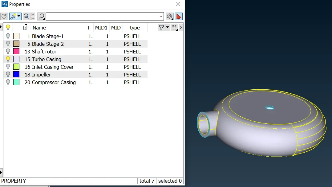
PID 5 - Turbo casing
Create a PID named Turbo casing and assign the bottom circular casing to it.
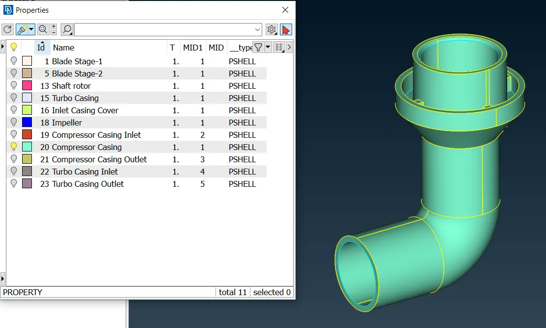
PID 6 - Compressor casing
Create a PID named Compressor casing and assign the outer casing to it.
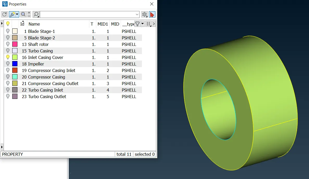
PID 7 - Inlet casing cover
Create a PID named Inlet casing cover and assign the component attached to the entry of turbo casing to it.
The inlet and outlet lids also needs to be assigned with PIDs as below
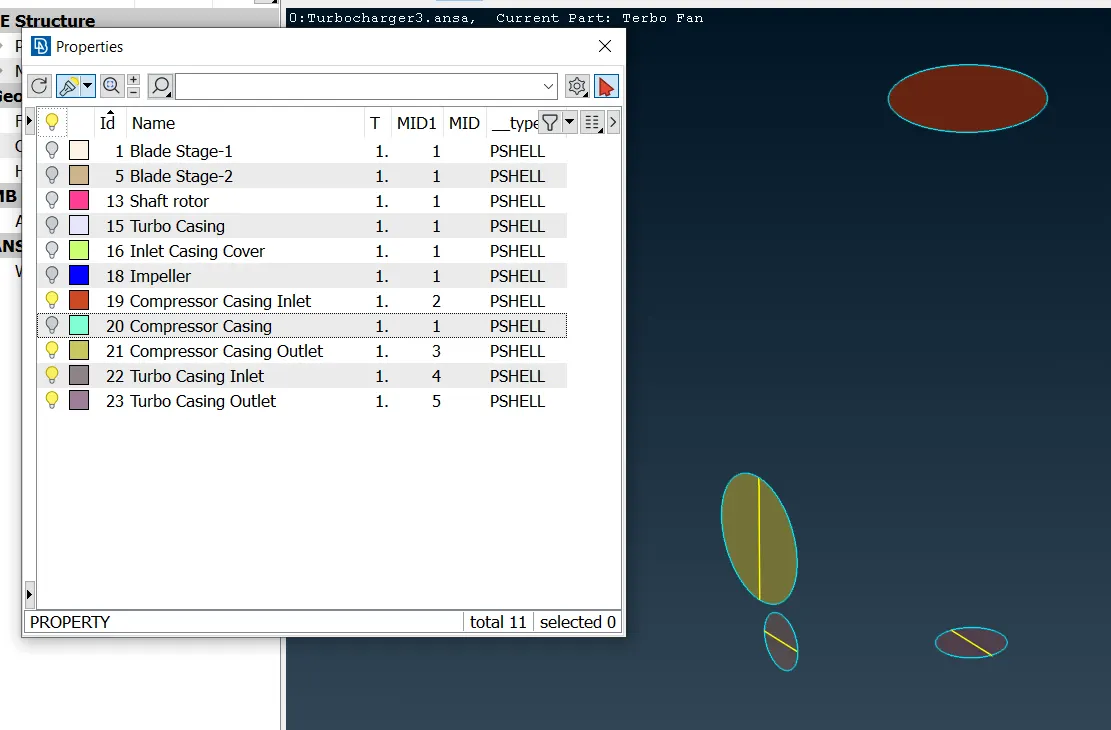
The next step is to do surface mesh (2D mesh).
For this, the given target lengths are given as
- Blade stage-1 = 1 mm
- Blade stage-2 = 1 mm
- Impeller = 2 mm
- Shaft rotor = 1 mm
- Turbo casing = 5 mm
- Compressor casing = 5 mm
- Inlet casing cover = 5 mm
The element type for mesh is "Tria".
Strat with meshing compressor casing for which the target length is 5 mm
As discussed before, the target length must be given in 3 places.
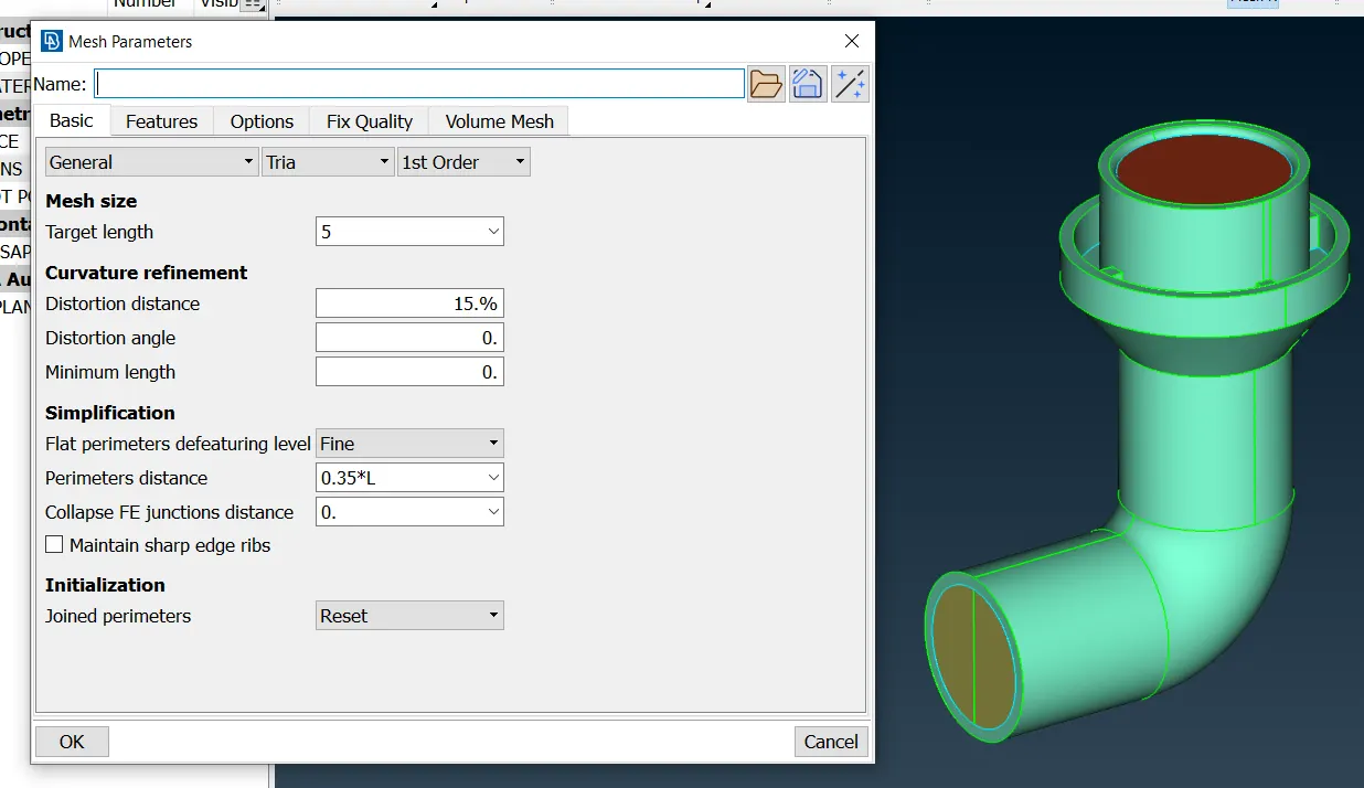
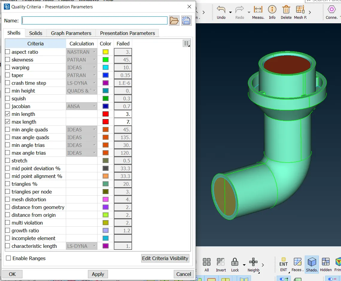
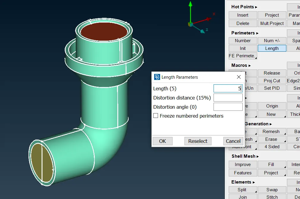
Next select the spot mesh and select all the faces.
The mesh is done as below
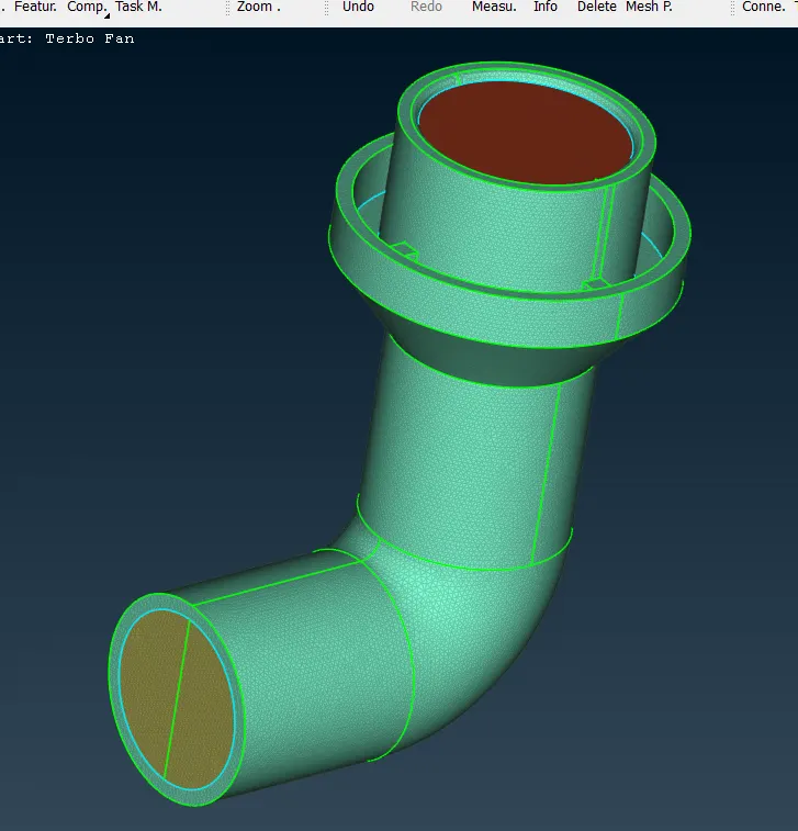
Similarly, do for all other PIDs based on the target lengths.
Inlet and turbo casing with 5 mm target lengths.
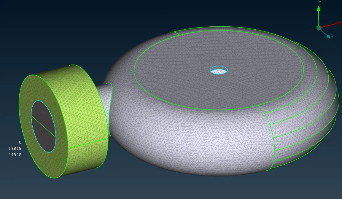
Impeller with 2 mm target length
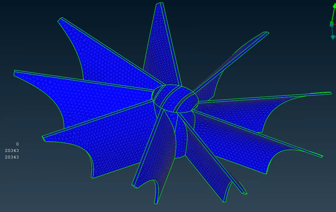
Shaft rotor, Blade stage 1 and 2 with target length of 1 mm.
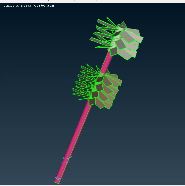
After completing the mesh, check if all the PIDs are mshed as desired.
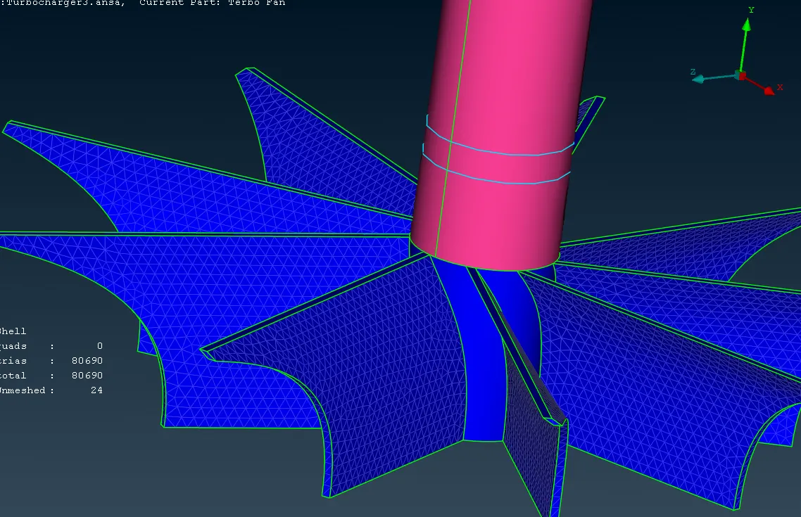
In the above picture, it can be seen that mesh is not done fully in some parts of impeller and shaft rotor.
This is because of the variation in mesh target length between these two PIDs. The impeller has target length of 2 mm whereeas the shaft has a target length of 1mm.
As they both share a common CON, the software will not be able to take one particular mesh length.
So, to rectify this, mesh length should be given in the form of range.
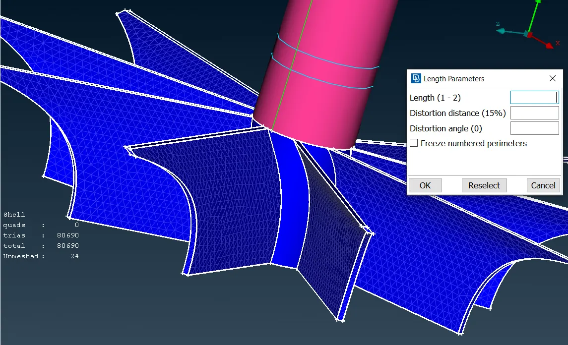
Instead of giving fixed value, since the mesh length is varying, let the length be in the range of 1-2 as above.
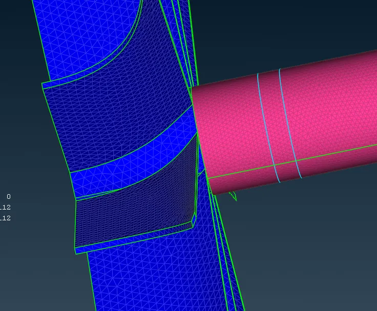
When the mesh is completed, it can be seen that the area of impeller which is closer to the shaft has a mesh lenghth close to 1 mm whereas the area away from shaft will have a mesh length of around 2 mm.
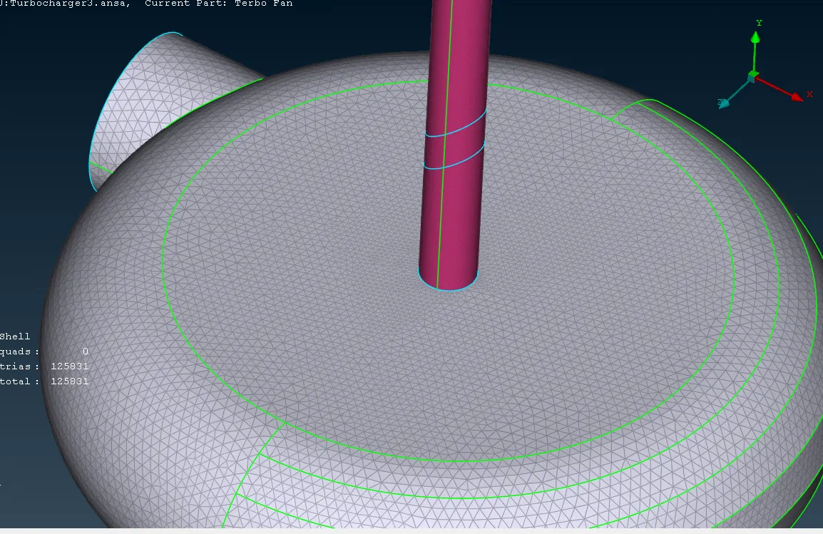
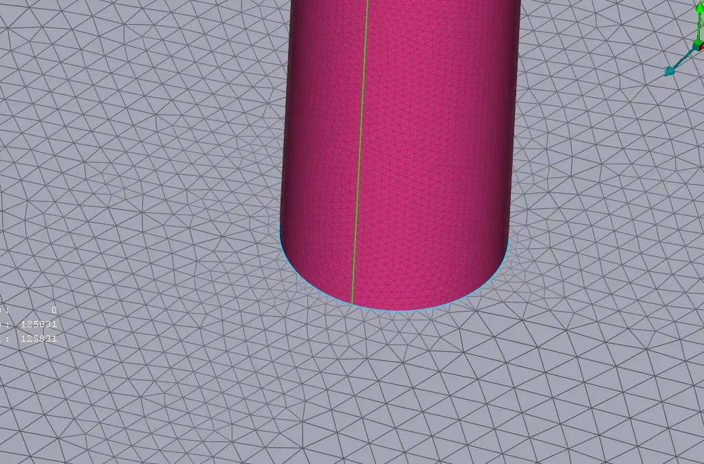
Similar state can be seen at the interfcae between turbo casing and shaft rotor. The elements in turbo casing that are closer to shaft are having a mesh length of around 1mm whereas the elemnts thar are far have mesh length of around 5 mm.
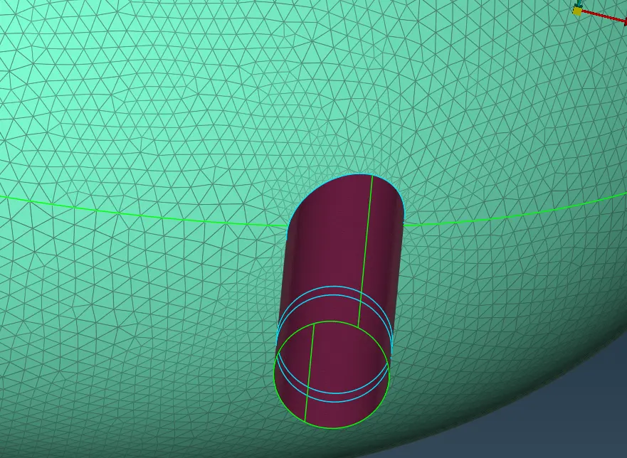
Similar state can be observed at the interface between compressor casing and shaft rotor.
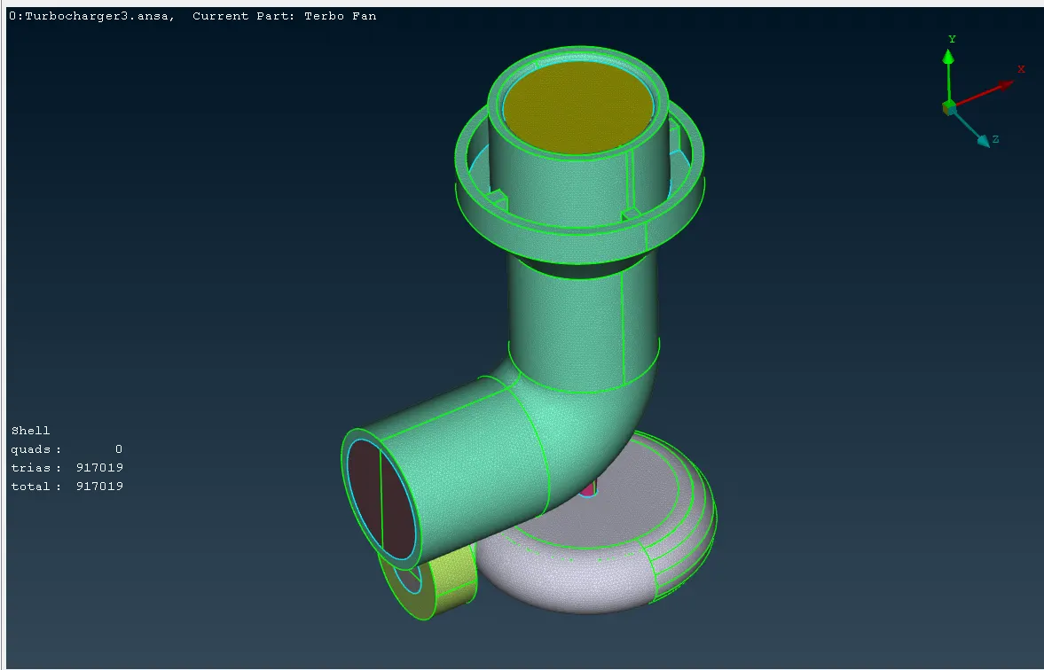
Turbocharger with 2D surface mesh :
Next step is to do Volumetric mesh (3D mesh).
In Vol.mesh,in the volumes section, click "Define".
It gives certain volumes in a list.
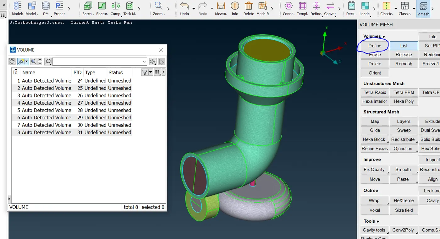
The above 8 volumes are all the volumes available in the entire model to do volumetric mesh.
Out of all these volumes, only the volumes through which the fluid flows should be done volumetric mesh.
Those volumes need to be identified in the above list.
For this, select each volume and check whether the particular volume is the one through which fluid flows.
Other volumes would be the thickness of the components and can be deleted as fluid will not flow through the thickness.
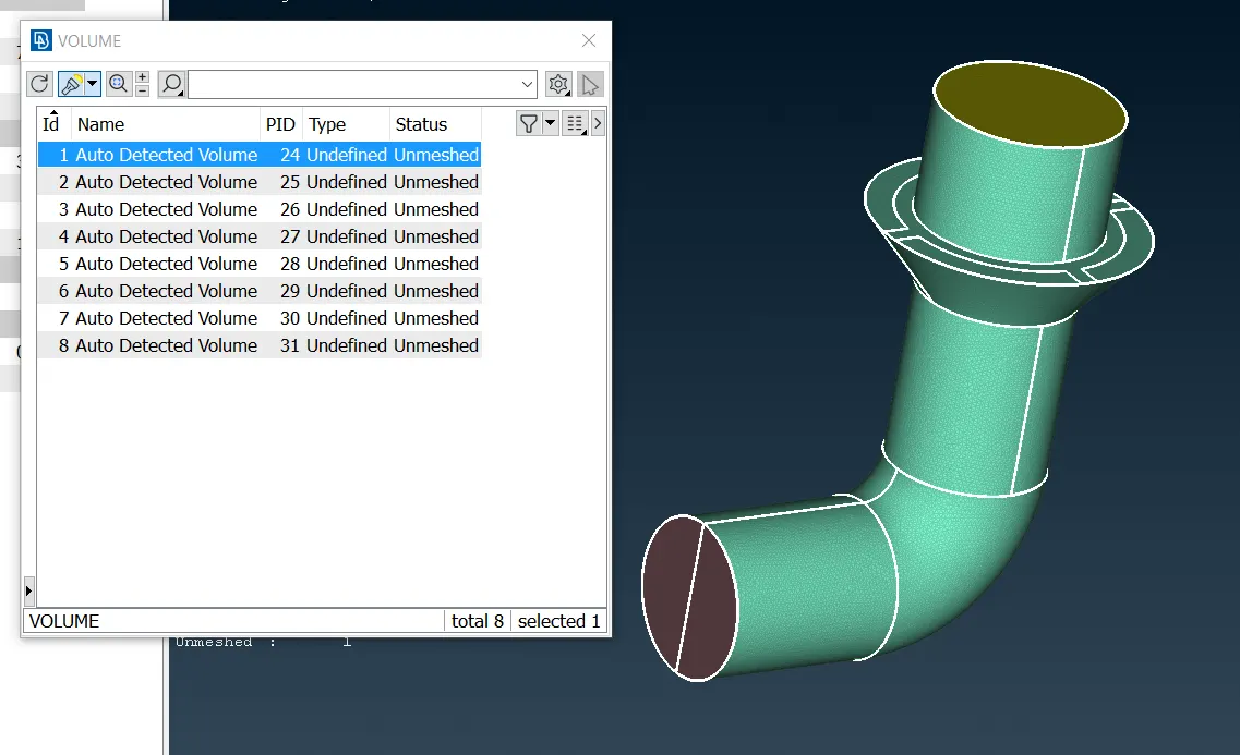
The first volume is the he volume trough which the fluid will flow. So, this needs to be done volumetric mesh.
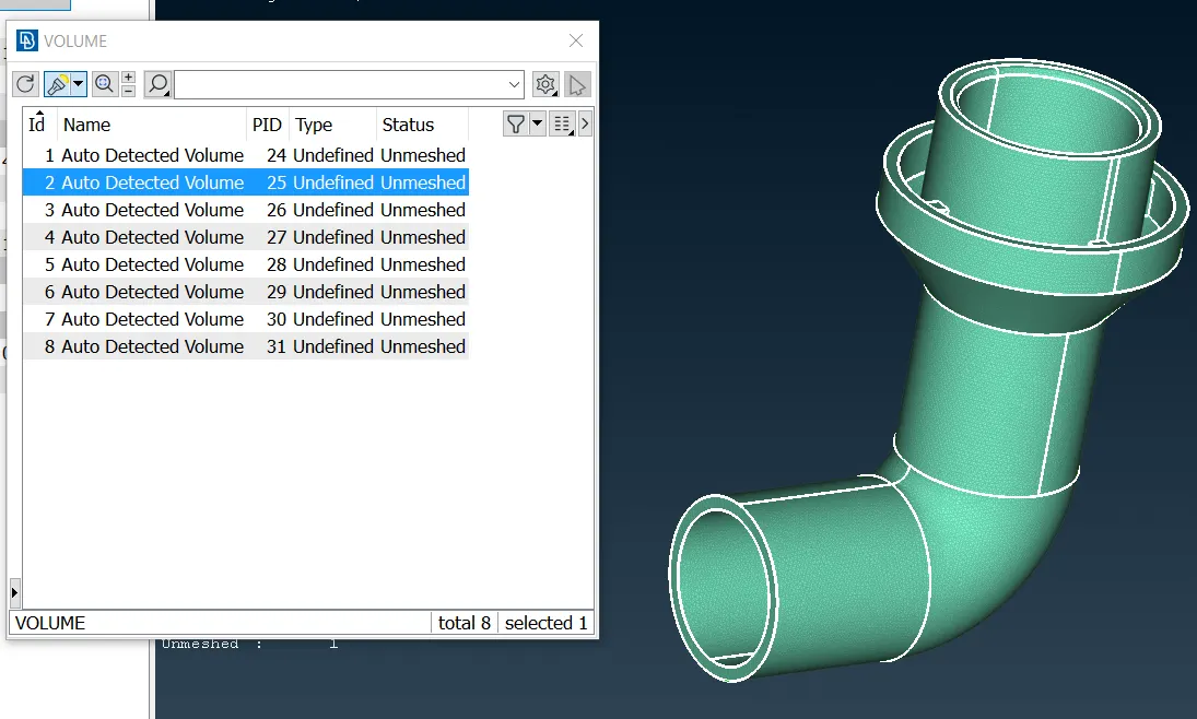
The second volume is the thckness of the compressor casing. Volumetric mesh should not be done on this and can be deleted.
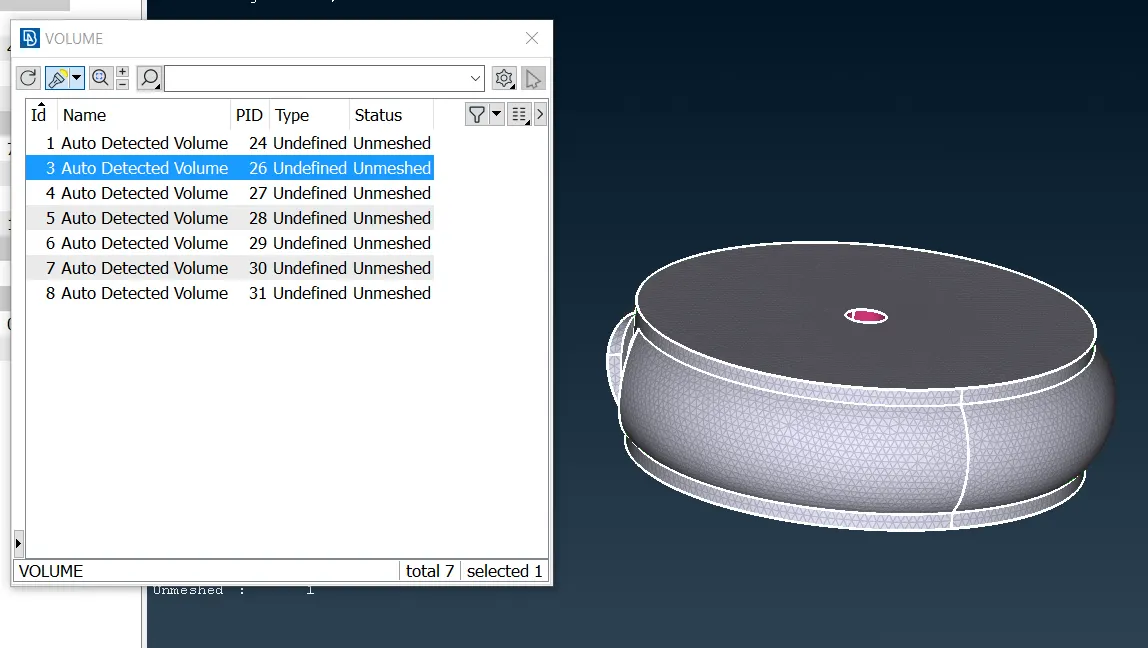
The third volume is the volume through which the fluid will flow inside the turbo casing. Vol. mesh should be done on this.
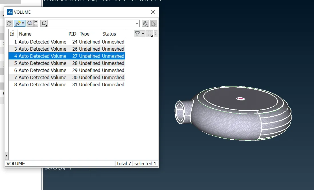
The fourth volume is the thickness of the turbo casing and can be deleted.
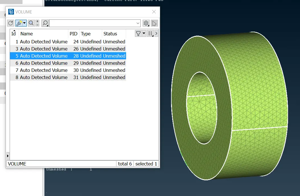
The fifth volume is the thickness of inlet casing through which the fluid will not flow and can be deleted.
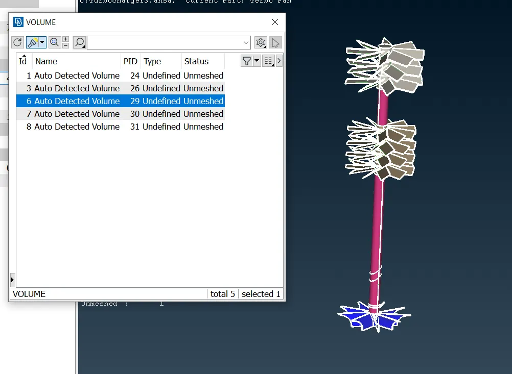
The sixth volume is the volume occupied by the blades and shaft through which the fluid will not flow and can be deleted.
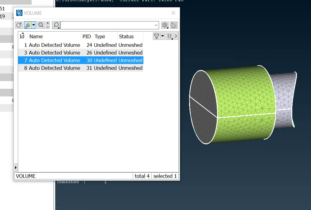
The seventh volume is the volume through which the fluid enters the turbo casing. Vol. mesh should be done on this.
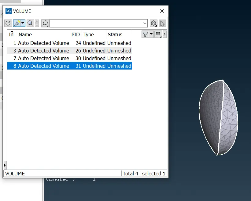
The eighth volume is also through which fluid will flow and vol. mesh should be done.
Total volume on which volumetric mesh should be done :
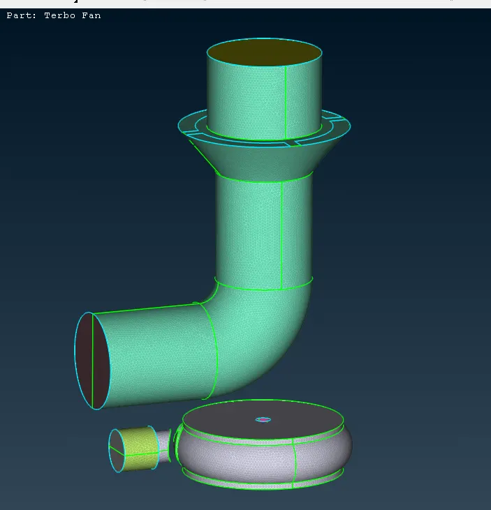
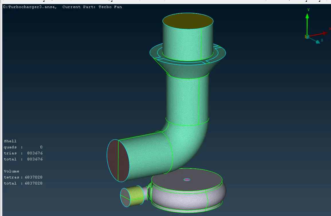
In the list of volumes, click each vilume and do vol. mesh using "Tetra CFD" element.
Turbocharger with Volumetric Mesh :
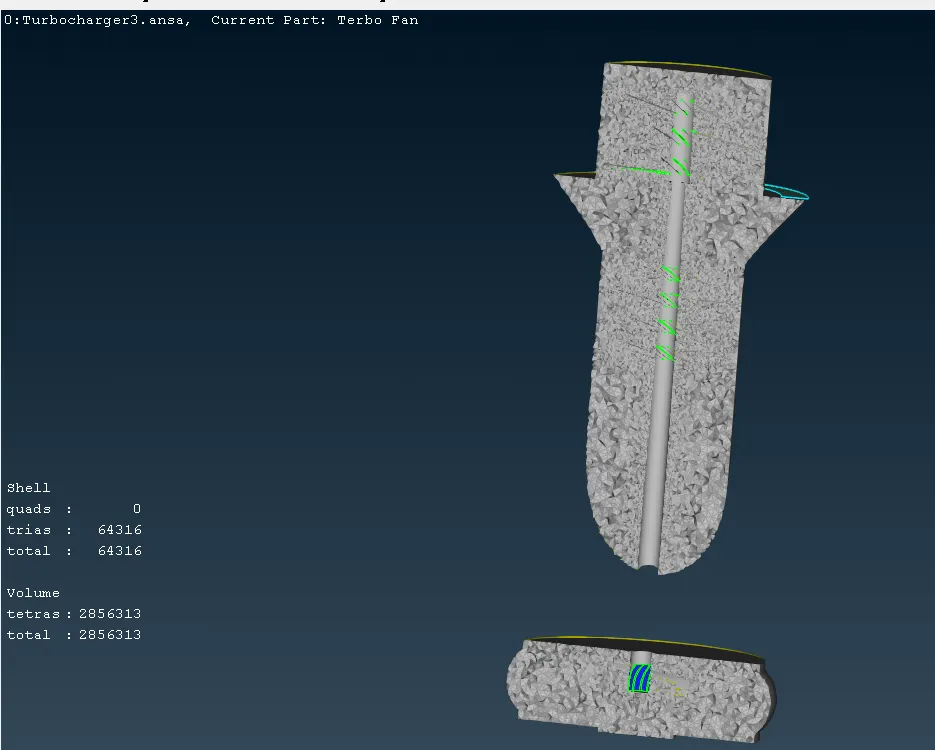
Section view showing the tetra elements :
The link for the meshed model is below :
https://drive.google.com/file/d/1NZIH6b_Y1JCEikIs12vDcdxI6O-v9Qm2/view?usp=drive_link