Week 3 Challenge : CFD meshing on Turbocharger
CFD meshing on Turbocharger
AIM:
For the provided turbocharger model, first, identify and rectify any geometric errors to ensure proper volumes. Next, establish and assign PIDs as needed. Then, generate a surface mesh and utilize it as the basis for constructing a volumetric mesh. Execute surface meshing using the specified target lengths in accordance with the provided PIDs:
Blade stage-1 = 1 mm
Blade stage-2 = 1 mm
Impeller = 2 mm
Shaft rotor = 1 mm
Turbo_Casing = 5 mm
Compressor_Casing = 5 mm
Inlet_Casing_Cover = 5 mm
Generate a volumetric mesh for the designated volumes.
PROCEDURE:
1. Topology and Geometry Clean-Up:
- Import the ANSA file by accessing the "Open" option in the file dropdown menu.
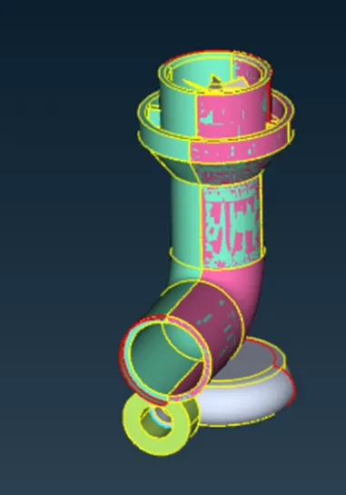
- We can see that a rose surface is overlapping with the cyan surface and it is not needed. Isolate those surfaces and delete them by global delete option.
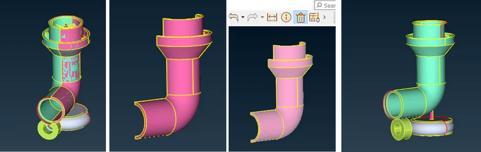
- Without going in to geometry check up itself we can see lots of single conns in the model. Isolate Turbo_Casing PID and lock the view.
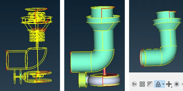
- Using Suitable options and strategies fix the single Conns in the locked PID. Initiate the process of filling surfaces and addressing single constraints by creating surfaces where necessary. In instances where the surfaces generated by the "new" option under faces do not conform to the required specifications, project specific hot points to create smaller surfaces, which can subsequently be joined to achieve the desired geometry. Utilize the "intersect" option to remove surfaces that lack distinct entities. This action creates separate entities through intersection, simplifying their deletion.

- Now unlock and do the similar procedure for all PIDs. Select the "Topology" option under faces and use a box selection to encompass the entire model, facilitating the detection of any missing constraints for a more precise geometry clean-up. With single constraints resolved, shift focus to addressing triple constraints, particularly in the shaft region. Reducing them to double constraints by deleting overlapping surfaces streamlines the process, as a single volume is preferable for ease of meshing in subsequent stages.
- Cleaned Compressor Casing

- Cleaned Turbine blades, Impeller, and shaft
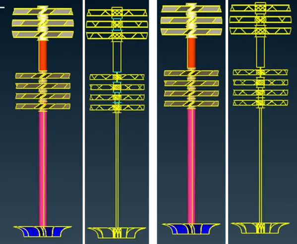
- Remove any overlapped surface if any and cap the openings for Volume extraction assign proper PIDs to every surfaces
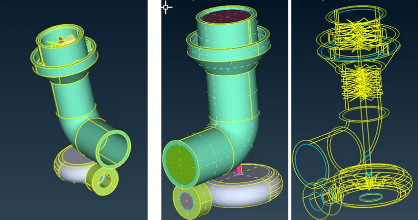
- Check from Geometrical error for finding out any other error remaining.
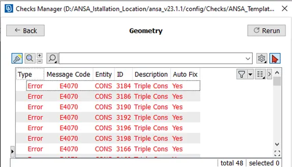
- The errors obtained were related to triple Conns and we have confirmed that those are not really errors my inspection.
- Once Done cross check all the PIDs. Following this, proceed to surface meshing.
2. Surface Meshing:
- Since the steps followed are hard to explain through images a video has been done and is given in the below link.
- It is essential to mesh each component in accordance with the criteria outlined in the question; therefore, individual component meshing is necessary.
- Specify the quality, mesh parameters, and mesh length for each component accordingly.
PID
Size (mm)
Blade stage-1
1 mm
Blade stage-2
1 mm
Impeller
2 mm
Shaft rotor
1 mm
Turbo_Casing
5 mm
Compressor_Casing
5 mm
Inlet_Casing_Cover
5 mm
- While determining mesh lengths, take into account the transition between components with differing mesh lengths. When they come into contact, there is a risk of one mesh erasing the other. To prevent this, establish a range that spans from the larger to the smaller mesh length when inputting perimeters and macros.
- After mesh generation, create a boundary for the variable mesh length and maintain a consistent mesh length on the opposite side of the boundary.
3. Volume Meshing:
- Once surface meshing is complete, proceed to volume meshing.
- Under volume meshing, select "Define" and choose the entire database. In the resulting pop-up window, ANSA identifies various volumes present in the geometry. Delete any unnecessary volumes, retaining only those relevant to fluid flow within the geometry.
- After removing the outer thickness volumes and retaining the fluid volume region, re-mesh each volume using the "Tetra CFD" option under re-mesh.
- Once each volume has been re-meshed, review the volume mesh for each component.
RESULT:
- Concluded the geometry clean-up process by closing all inlets and outlets, thereby establishing a sealed volume.
- Successfully executed surface meshing, adhering to various mesh lengths as specified in the question.
- Generated a volumetric mesh for the fluid volume region, including cut sections to facilitate 3D mesh visualization.
LEARNING OUTCOME:
- Verify the geometry for errors and utilize various geometry editing tools for corrections.
- Eliminate overlapping regions to enhance mesh quality and prevent volume meshing errors.
- Adjust triple and single constraints as needed to align with the geometry specifications.
- Employ the "fine" setting under auxiliary tools to achieve a smoother surface finish at connecting regions.
- Generate surface meshes individually while maintaining mesh length consistency at contact regions between different mesh lengths.
- Isolate and generate volume meshes exclusively for the fluid region. 7. Utilize available tools for volume mesh creation.
CONCLUSIONS:
- Attained a volumetric mesh for the turbocharger model.
- Varying mesh lengths can introduce errors at the interfaces between regions with different mesh sizes; hence, it is advisable to establish mesh ranges to prevent mesh erasure.