Week 3 Challenge : CFD meshing on Turbocharger
Aim of the project - To eliminate the topological errors that are acquired in the given a turbocharger CAD model and then perform the surface and the volumetric with the different mesh length that is given in the problem.
Before going to do the we had to do the following operations-
1)
#) Turbocharger-
A turbocharger (abbreviated T or T/C), formally a turbosupercharger and colloquially known as turbo, is a turbine-driven, forced induction device that increases an internal combustion's power output by forcing extra compressed air into the combustion chamber This improvement over a naturally aspirated engine power output is because the compressor can force more air—and proportionately more fuel—into the combustion chamber than atmospheric pressure (and for that matter, ram-air intake alone.
The key difference between a supercharger and the supercharger are the conventional supercharger are mechanically driven and the turbocharger is driven by the turbine power extracted from the engine's exhaust.
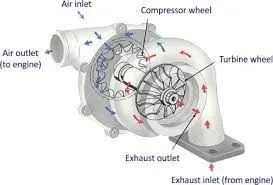
#) The schematic of a turbocharger
#) Procedure-
1) cleaning up the geometry-
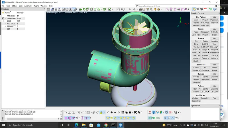
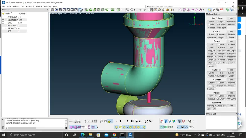
#) after removing the extra surfaces we get the following
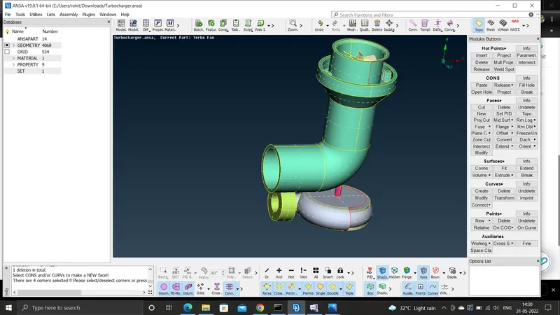
#) One extra surface is removed and a new surface is made -
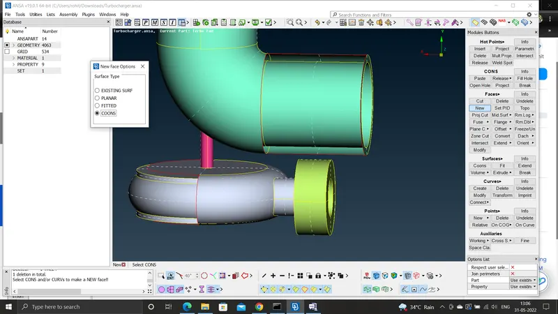
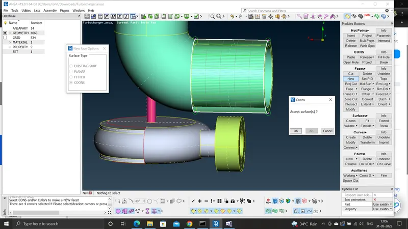
#) The cleaning procedure is continued by the following procedure-
Inside the shaft section the extra surface in the shaft have to be deleted so that we can see through the entire length of the shaft . The extra surface would cretae the problem during meshing. And while deleting the surface some extra single cons are created which are to be removed or rectified by Topo tool by doing the entity selection of the single cons
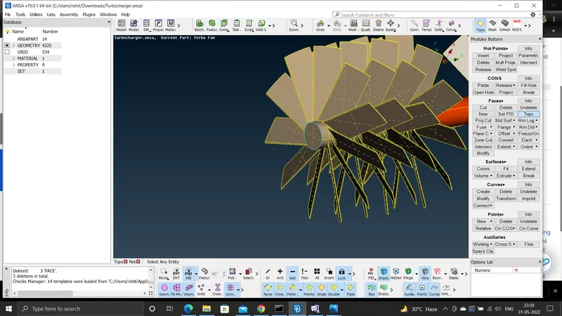
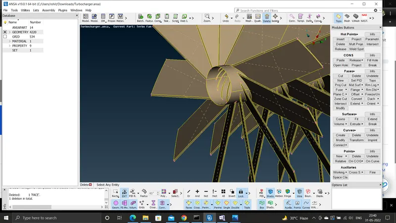
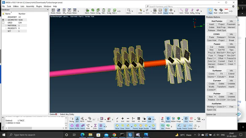
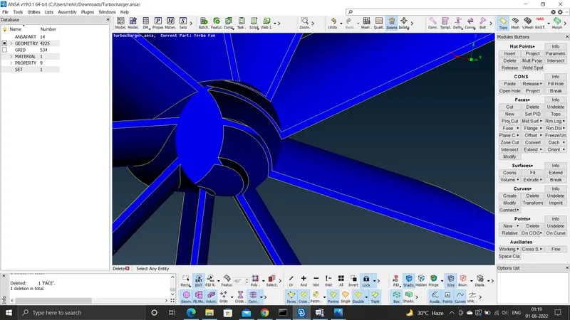
#) In the Impeller section we need to create the surfaces to close the geometry of the impeller casing -
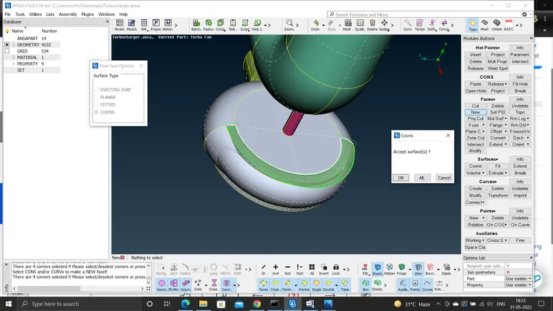
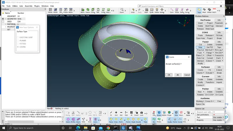
#) The final surface created is like this -
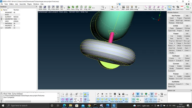
#) Next the geometry is cleaned up further like-
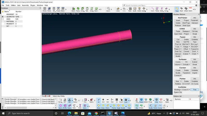
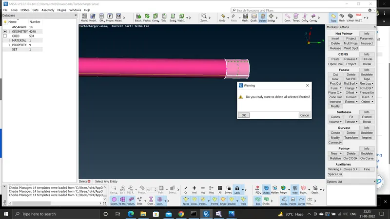
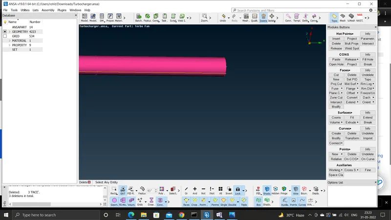
#) All the open surfaces need to be closed so that we can extract the fluid vi=olume that would be useful for the CFD analysis-
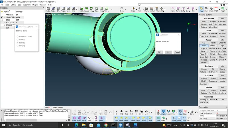
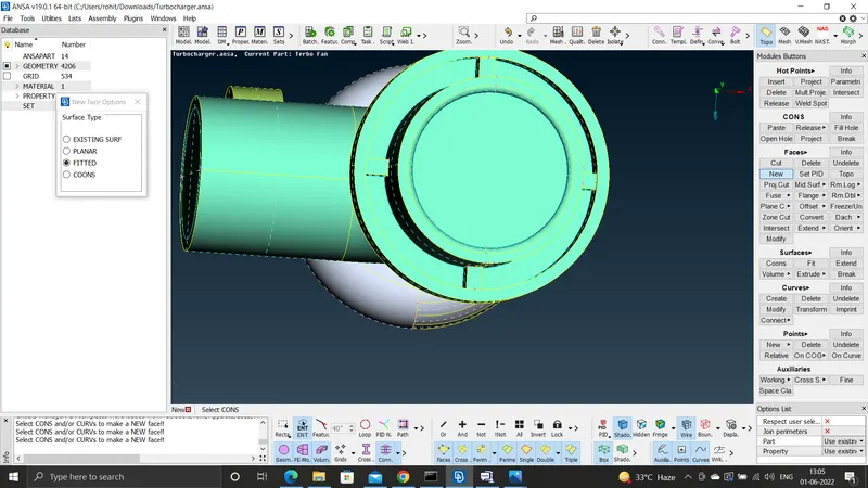
#) The different PIDS are already present already and some new PIDS are to be created like the inlet casing , compressor casing and the outlet casings -
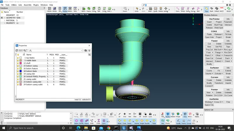
#) Now we move on to the surface meshing - we have to give a different length for the different components-
- Blade stage-1 = 1 mm
- Blade stage-2 = 1 mm
- Impeller = 2 mm
- Shaft rotor = 1 mm
- Turbo casing = 5 mm
- Compressor casing = 5 mm
- Inlet casing cover = 5 mm
After meshing the turbo casing with the 5 mm length we obtain the following -
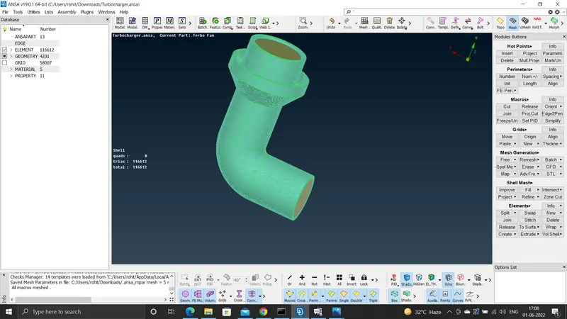
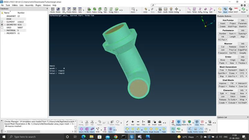
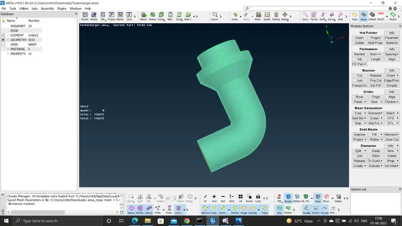
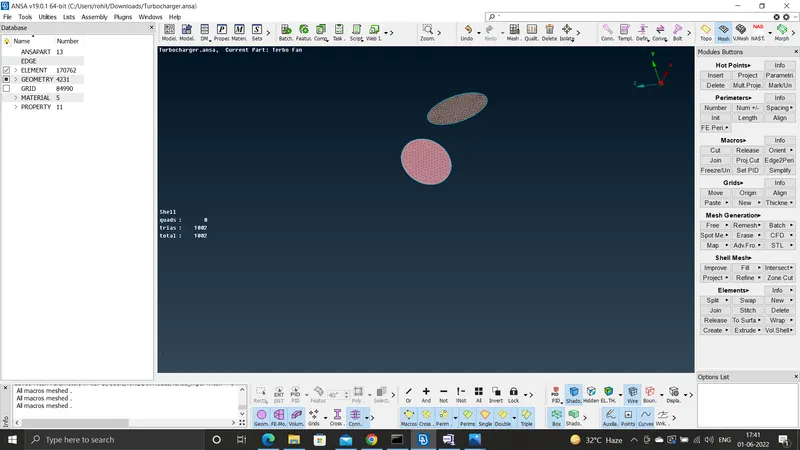
#) The inlet and the outlet casing are given element length = 1 mm the thing that is obtained as -
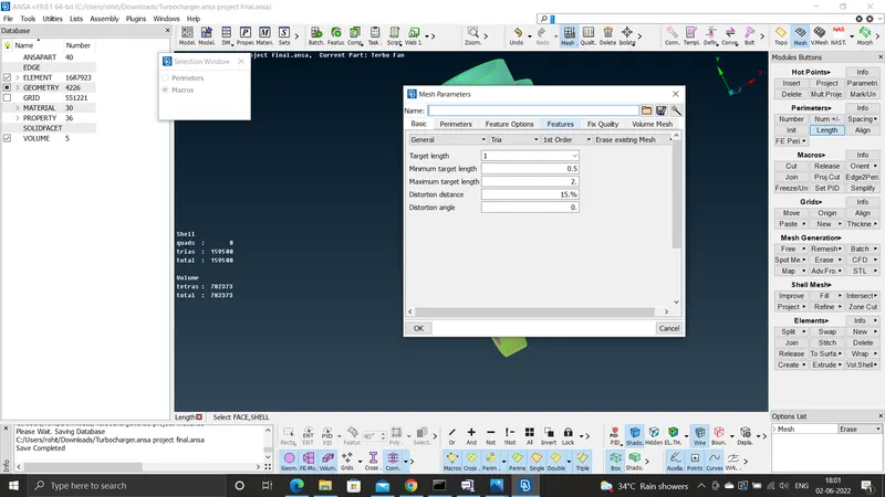
#) while meshing we will use the length and give the perimeter and the macros by selecting the PID and the entity mode and give the length as the element length , the mesh and quality is given as following -
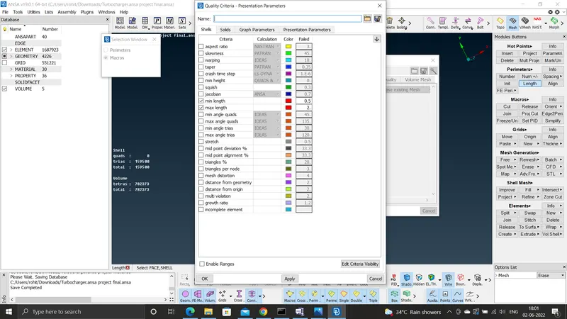
#) Next the Impeller blades is meshed by the element side is of 2 mm -
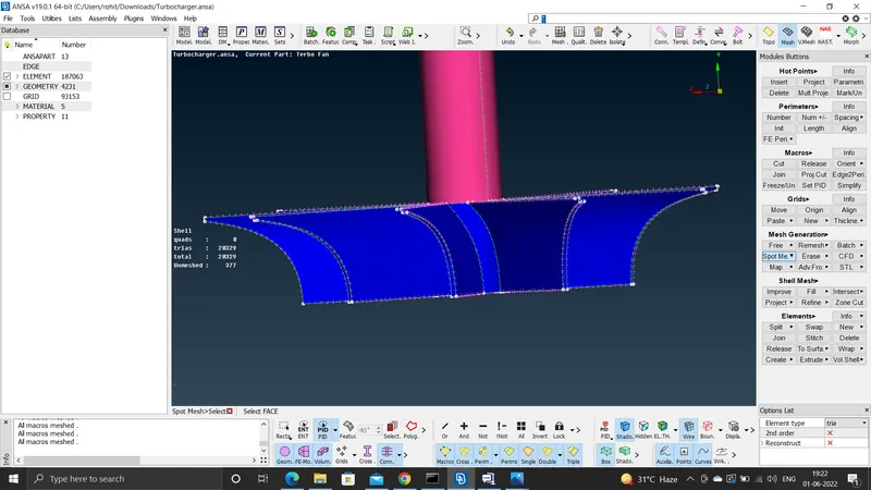
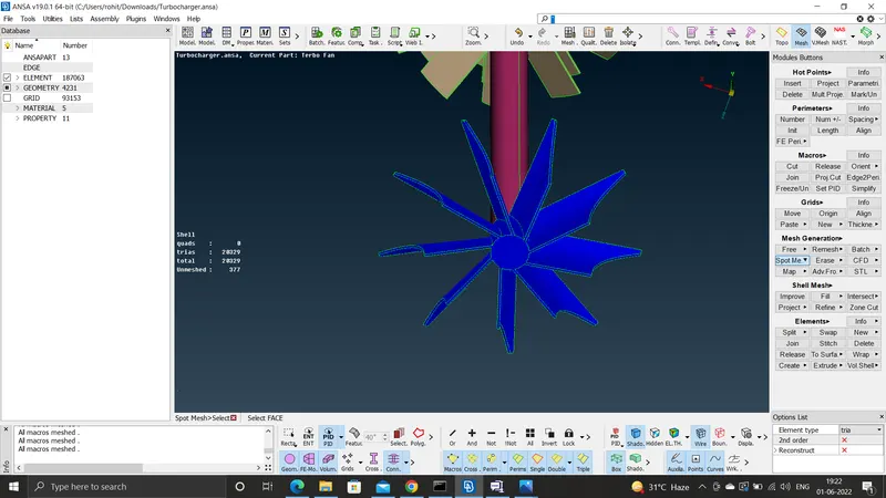
#) Next the two compressor blades are meshed using the length of 1 mm in the PIDS are named as blade stage1 and blade stage2-
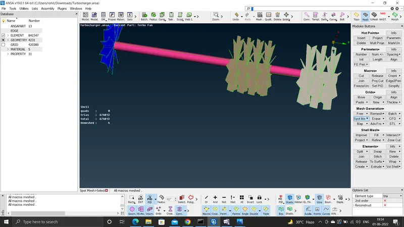
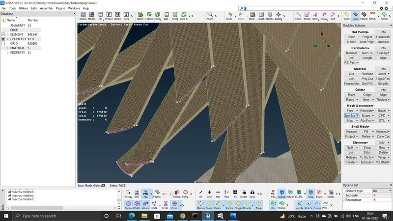
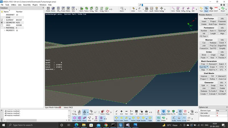
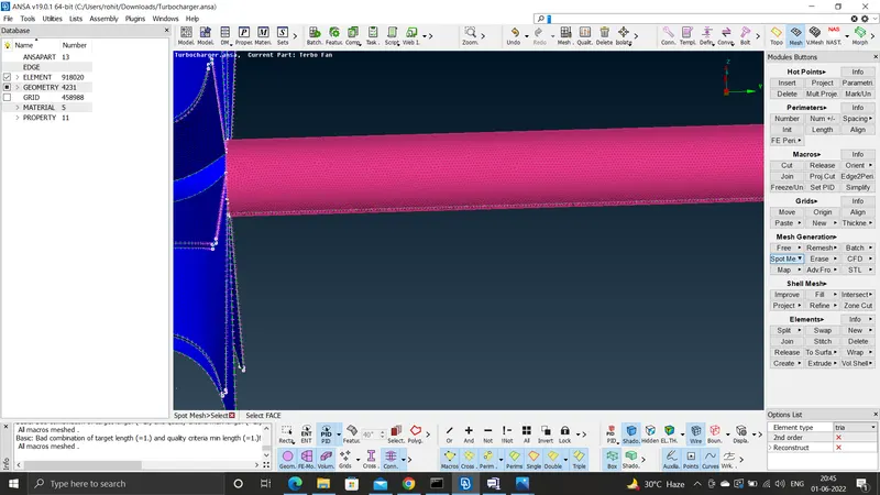
The final surface meshc reated is of -
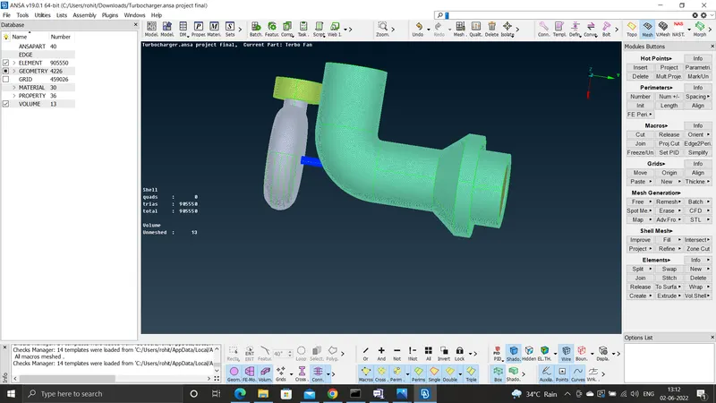
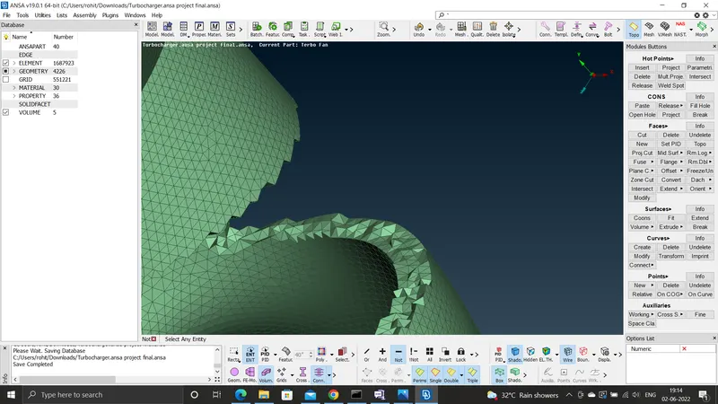
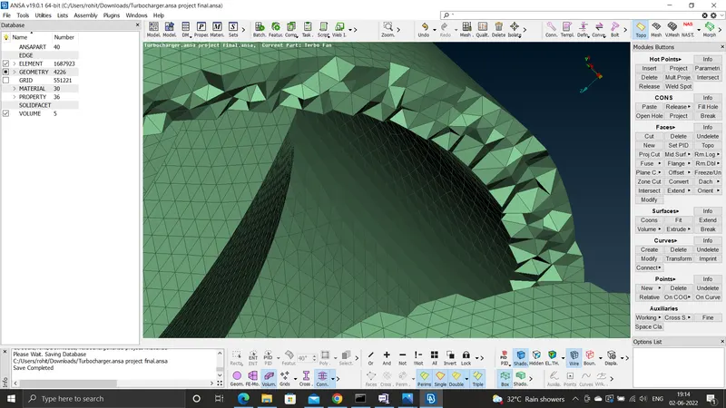
#) then we move to volume mesh-
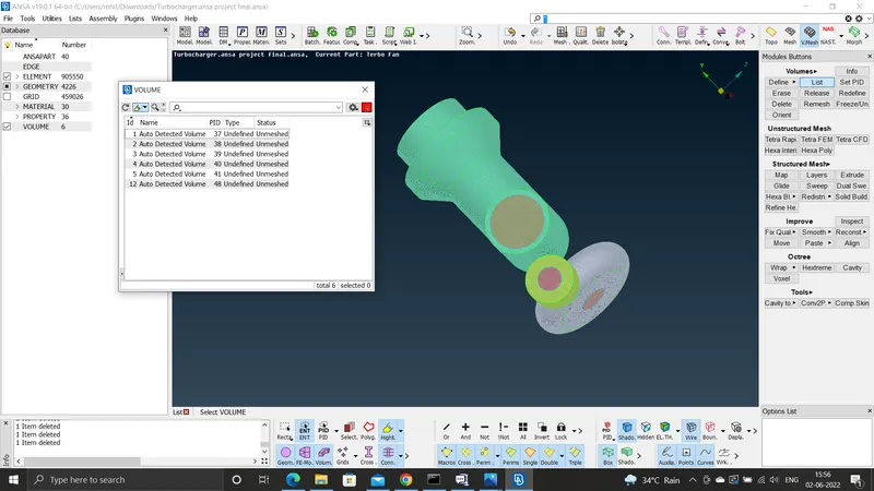
#) Now we are going to do volume mesh by clicking on to the each and individual volumes and then go to remesh and do tetra CFD- The teta CFD meansw the element size is of tetrahedral and the application of the element is of the CFD
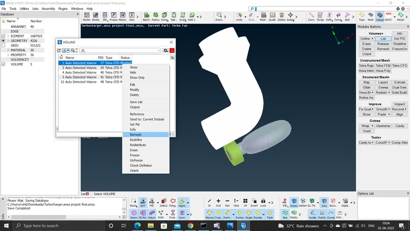
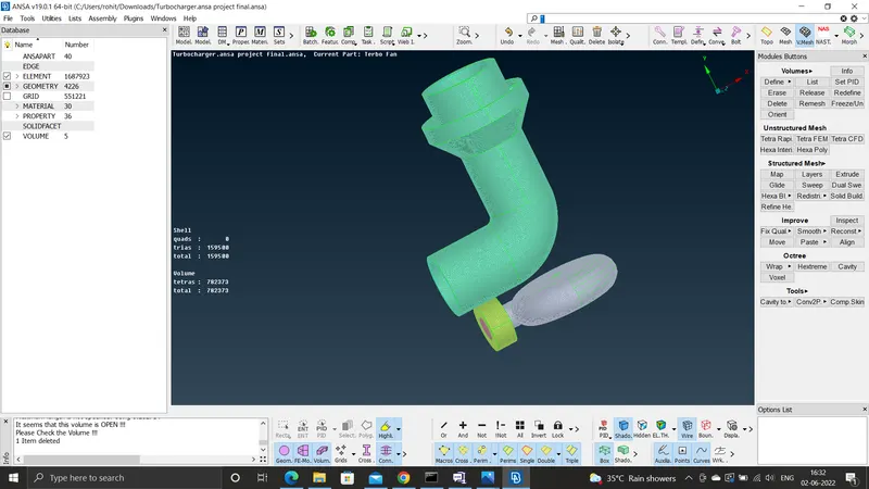
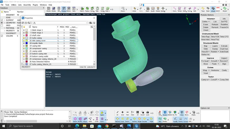
The final volume mesh is -
The link to the file is -
https://drive.google.com/file/d/166N_BzUyR-qmE8GjvFpo9S5VHKYAXNf6/view?usp=sharing