Week 3 Challenge : CFD meshing on Turbocharger
CFD meshing on Turbocharger
Aim:
The aim of this project is to generate an effective and high-quality computational fluid dynamics (CFD) mesh for a turbocharger, facilating accurate simulations of fluid flow and performance within the turbocharger.
Introduction
The introduction sets the stage for our exploration of CFD meshing applied to turbochargers. CFD meshing is a crucial step in the quest for precision. It involves identifying geomentrical errors, creating Property IDentifications (PIDs) for different components, and meshing surface to the desired specifications. Our journey includes target lengths for various components, such as Blade stages, Impellers, shaft rotors, and casing , each contributing to the overall turbocharger’s intricate design. We also delve into the volumetric meshing, which enables a more detailed understanding of the flow patterns within these systems.
This report is the result of a through examination of the meshing process. It aims to provide a clear and detailed account of the steps taken to optimize the mesh structure for CFD analysis. Through this exploration, we aim to shed light on the significance of accurate meshing and its important and design of turbochargers.
Procedure
The main of the given challenge is to perform surface mesh and volume mesh on the turbocharger and also geomentry cleanup with the surface mesh for the PID’s. Perfrom the surface mesh with the given target length as,
1. Blade stage-1 = 1mm
2. Blade stage-2 = 1mm
3. Impeller = 2mm
4. Shaft rotor = 1mm
5. Turbo casing = 5mm
6. Compressor casing = 5mm
7. Inlet casing cover = 5mm
Geomentry Cleanup:
· Open the ANSA software and import the turbocharger model and perform through check for any geomentrical errors or irregularities. Rectify any issues to ensure a clean and accurate geomentry for meshing.
· Start with topo clean by doing geomentry check to find single and triple cons in the geomentry. Select topo under faces and box select the entire model so that any missing cons can be detected and the geomentry cleanup can be done more accurately.
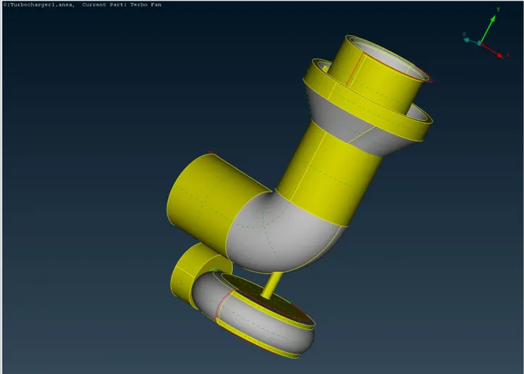
· As we can see the geomentry has errors in the above image. We need to clean up the geomentry from the interior and exterior errors.
· Identify and rectify any geomentrical erros or inconistence in the model. This steps critical for simulations
· Before clearing the surface and the single cons we need to delete the overlapping surfaces.
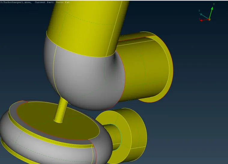
· In here we delete the overlapping surfaces to create a new surface.
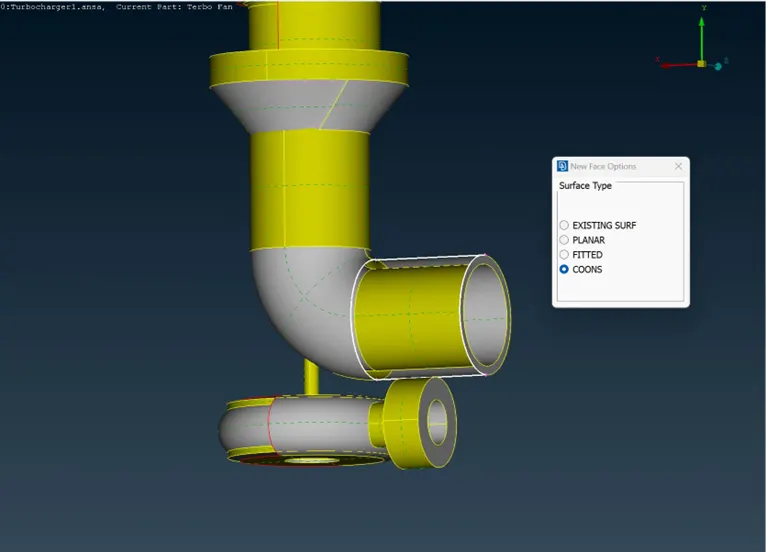
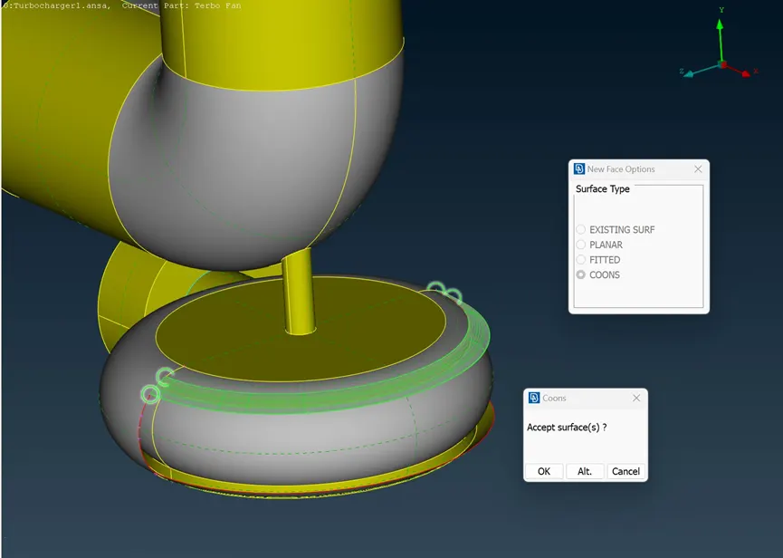
· In order to create a new surface we need to go with Topo clean up à Faces àclick New to create a surface à select Coons option to create a surface.
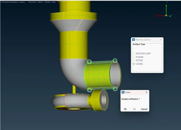
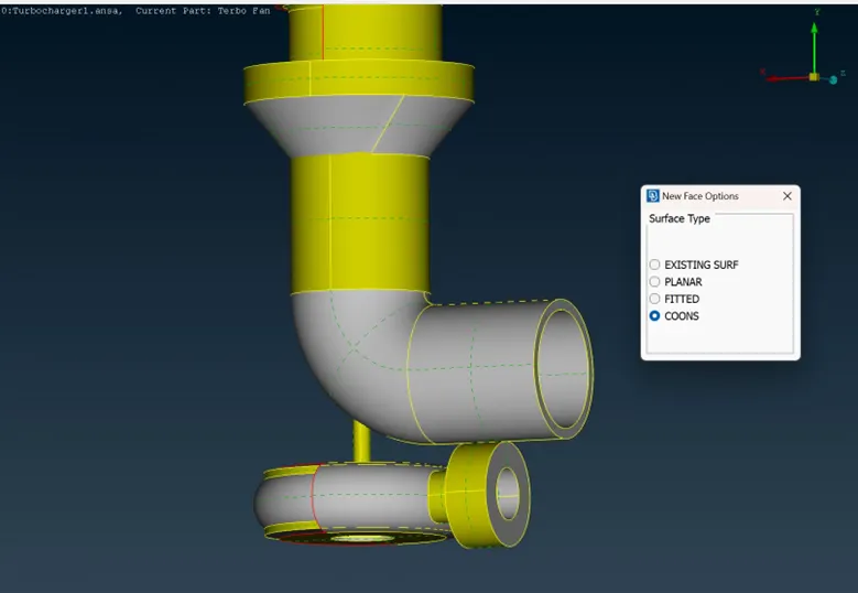
· Here we can see the new surface has been created by using Coons.
· Create surface like this where all the overlapping surfaces are there.
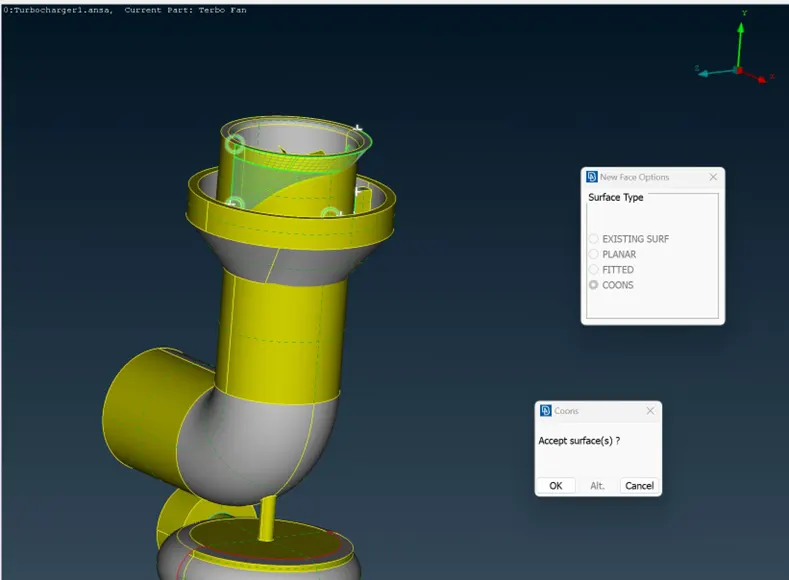
· In here we cannot able to create a surface after deleting the overlapping surfaces, so that we can create a hot points to create a proper surface.
· Selecting Hot points in the Topo Cleanup à Multiproject and select the points to create a surfaces.
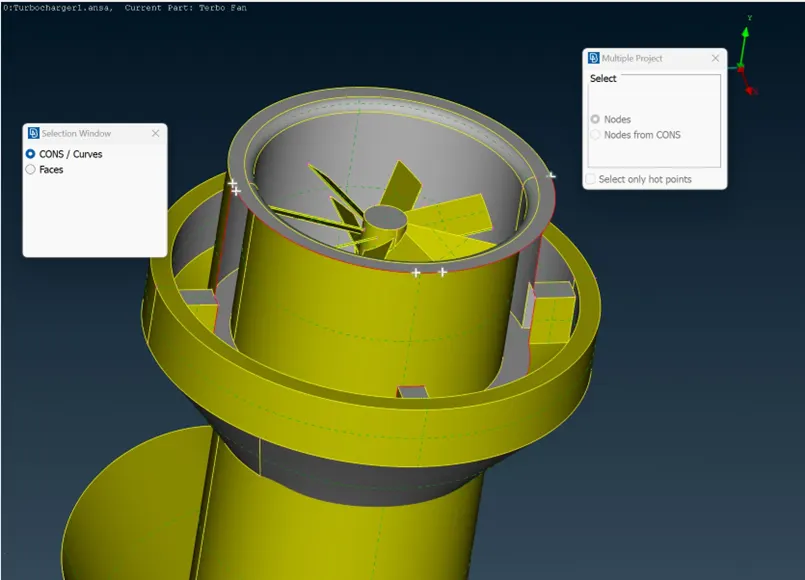
· After selected the hot points and created, the surface needed to created.
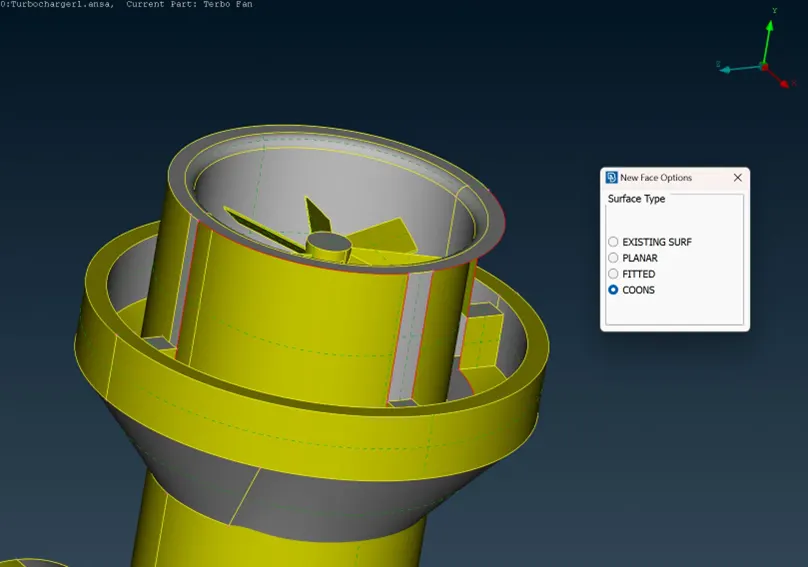
· Here after creating the hot points now we can create a surface.
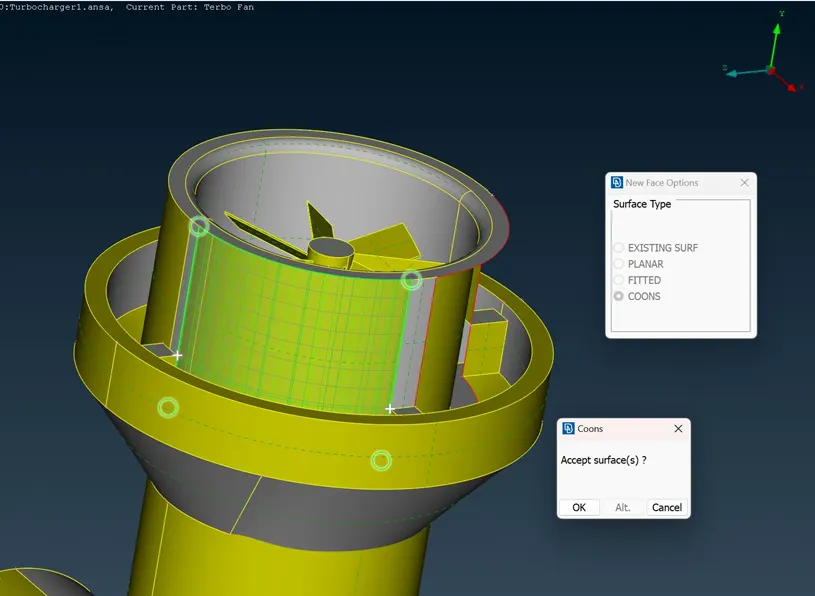
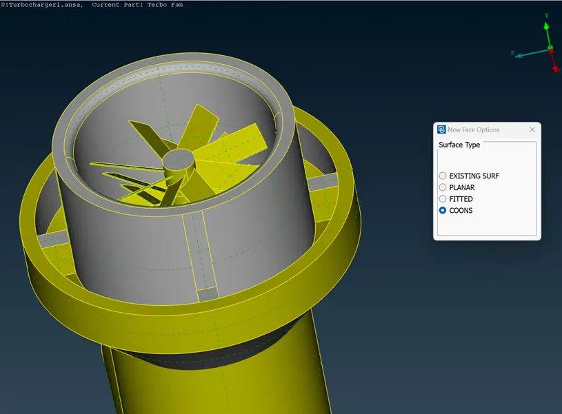
· Surface has been created for the inlet surfaces.
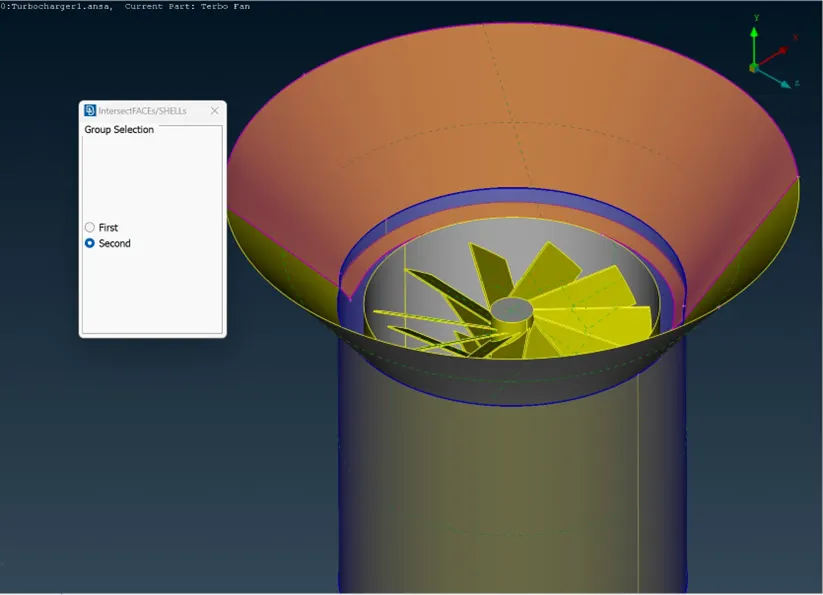
· Now isolate surface by using NOT option to delete the overlapped surfaces. In here we cannot delete just like In the previous ways so we can use the new tool INTERSECT to select and create a surface.
· The intersect option is to delete the surface which has no separate entity, therefore a separate entity is formed when suing intersect and can be deleted easily.
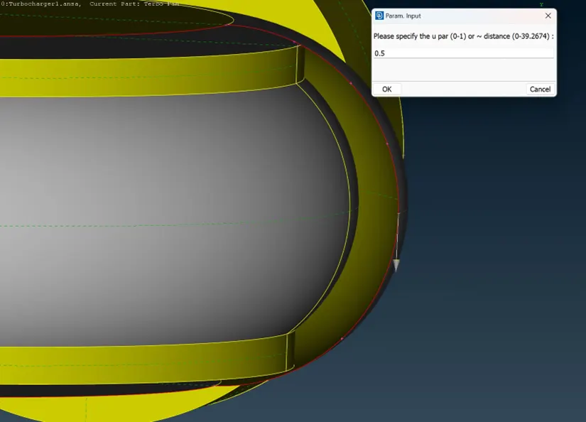
· In the above image the surfaces cannot be created just like old ways so for that in the turbo casing the certain areas created by using the new option faces don’t satisfy the surface we require, therefore certain hotpoints are projected so that small surfaces can be created and later can be joined and get the required geomentry.

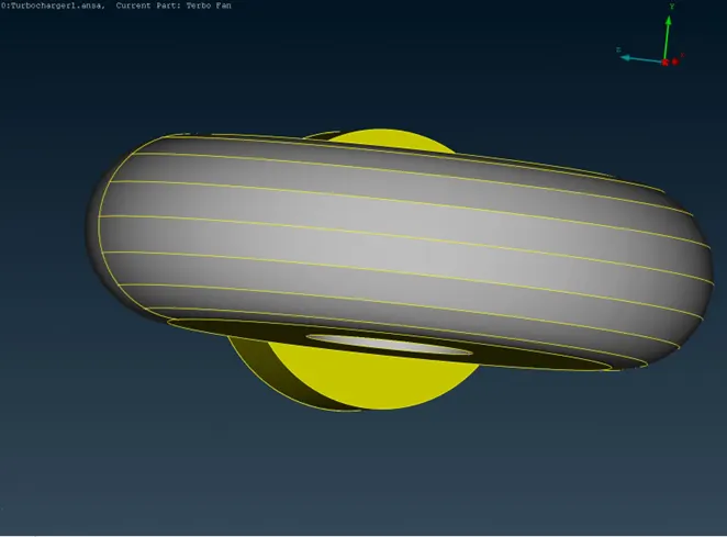
· This image shows that the outer layer of the surface has been created in the turbo casing.
· Once the single cons are solved for, we can focus on solving for triple cons which are present at the shaft region.
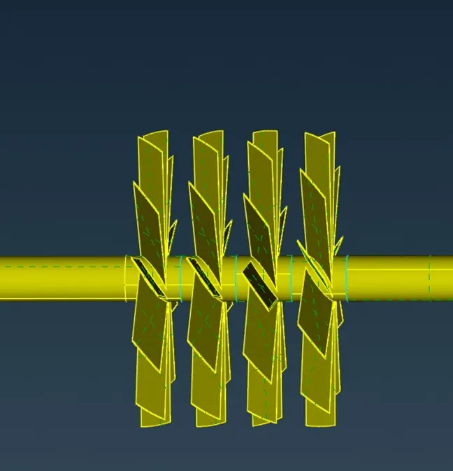
· We need to have a single vvolume which makes it easier to mesh in the later stage. Delete the overlapping surfaces to reduce them to double cons.
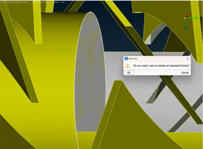
· Here there are overlapping surfaces are to be selected and deleted by using delete option.
· After the unnecessary triple cons are removed, we can start naming each part by assigining them an individual PID. After naming them, we can move ahead with surface meshing.
Assinging relevant PID’s:
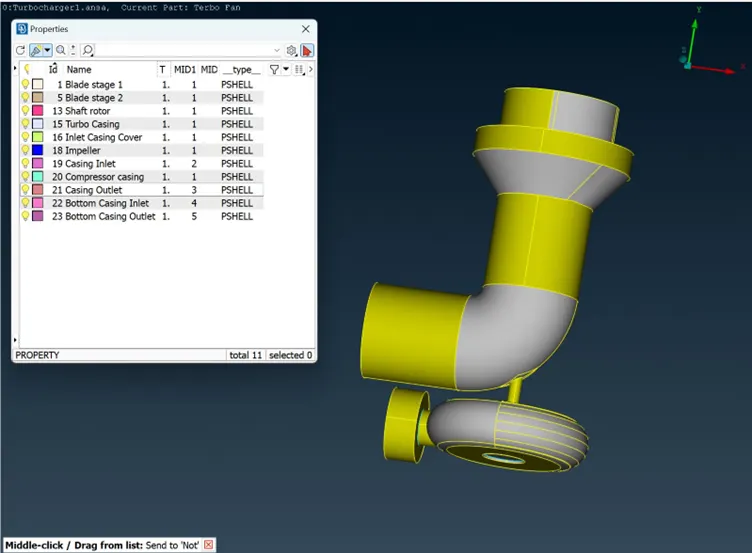
· In this image show Blade 1 and Blade 2 are selected and named.
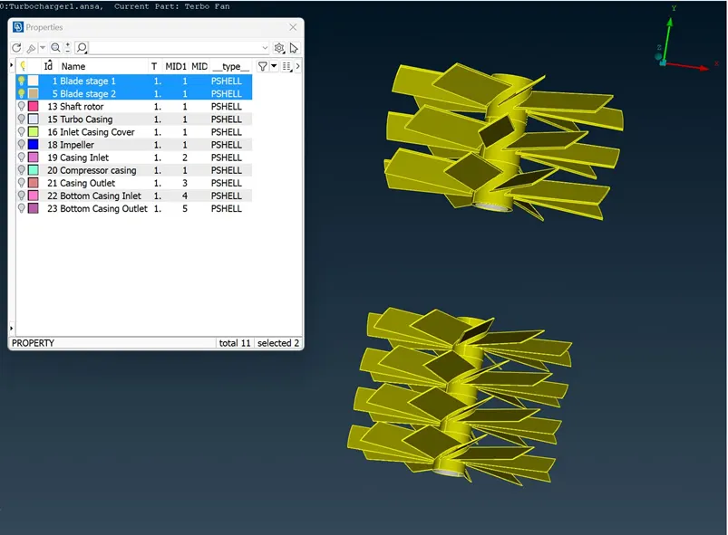
· In this image show Blade 1 and Blade 2 are selected and named.
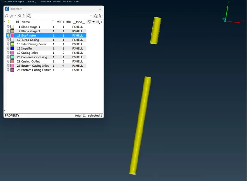
· In here the image shows that the Shaft rotor is named.
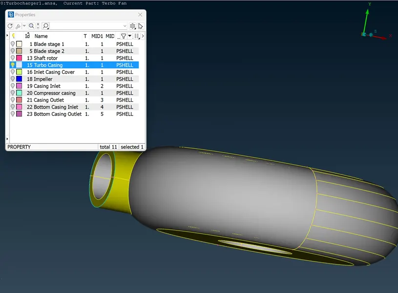
· It shows the Turbo casing is named in the properties.
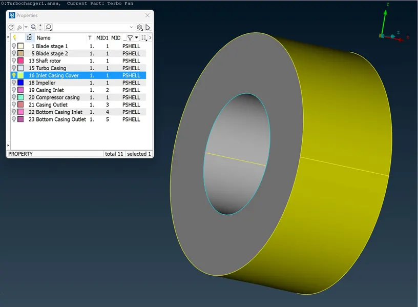
· This image shows that the Inlet Casing Cover is selected and named in the properties.
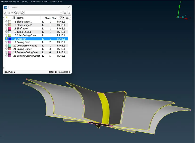
· This image shows that it is selected and named as Impeller in the properties.
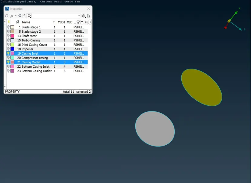
· This image shows that the Casing Inlet and Casing Outlet in the properties manager.
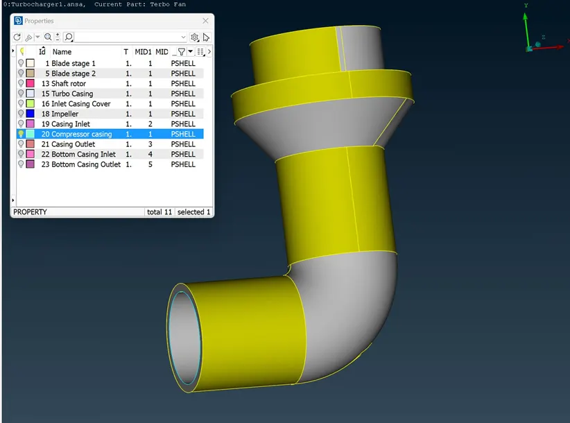
· This image shows that the Compressor casing is named in the properties manager.
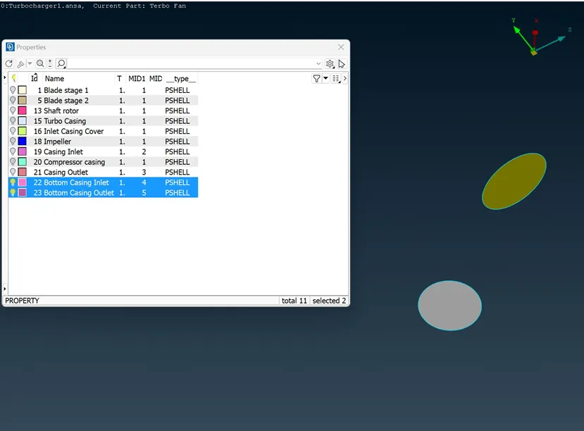
· In here shows that the Bottom Casing Inlet and Bottom Casing Outlet are named in the properties manager.
· Now after naming all parts in the PID’s we are ready to be meshed.
Surface Meshing:
Perform surface meshing of the turbocharger componenets. The meshing process should follow specific target lengths for different parts of the turbocharger, as indicated as below:
1. Blade stage 1 = Target length 1mm
2. Blade stage 2 = Target length 1mm
3. Impeller = Target length 2mm
4. Shaft rotor = Target length 1mm
5. Turbo charger = Target length 5mm
6. Compressor casing = Target length 5mm
7. Inlet casing cover = Target length 5mm
We need to mesh each component as per given criteria in the question, therefore we need to mesh the component individually.
Enter the quality and mesh parameters and the length of the mesh accordingly for each component.
1. Blade stage 1
2. Blade stage 2
Blade stage 1 = Target length 1mm
Blade stage 2 = Target length 1mm
Quality criteria
Minimum Target Length = 0.5
Maximum Target length = 2
Mesh Parameters
Target length = 1
Minimum Target Length = 0.5
Mesh Type = Tria
· In here we give value for the target length of the Blade 1 and 2, and setting up the value for the maximum length and minimum length.
· After giving the values now we can mesh both the blades.
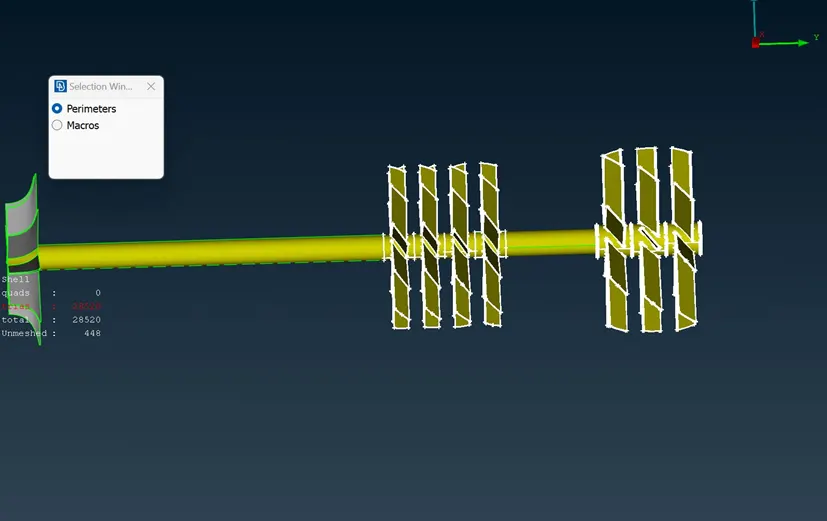
· Select the Mesh module button à Parameters à length à Perimeters
· Drag the cursor to the blades and select both the blades, now click on the middle mouse button and give the mesh value size as 1mm.
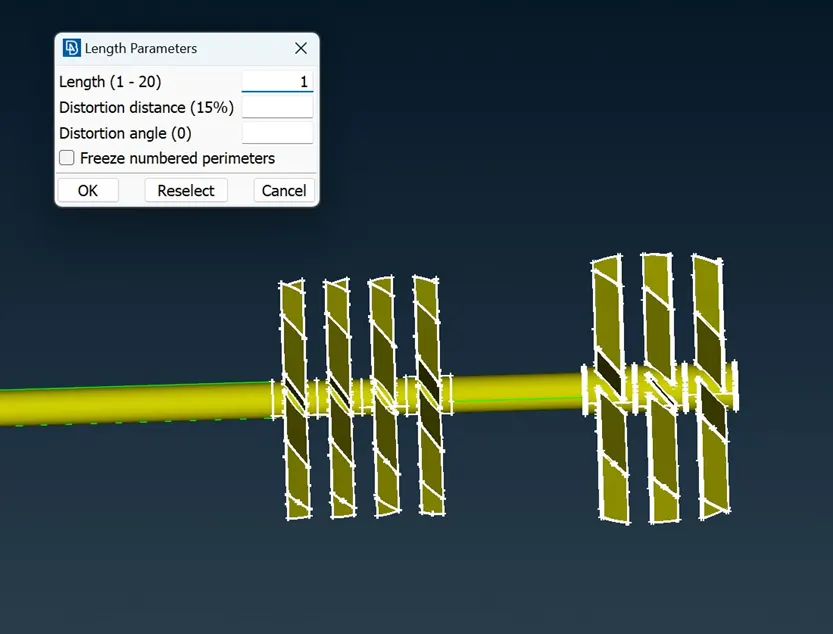
· Same as for Macros, we do the same process
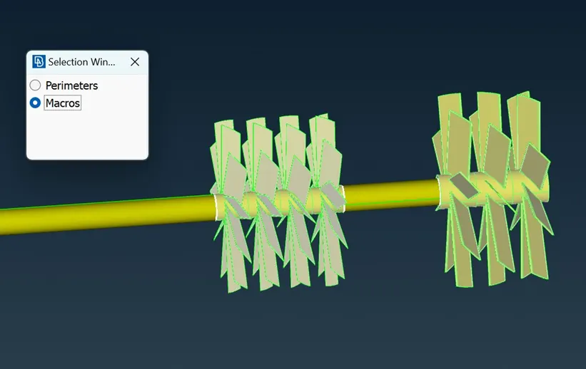
· Select the Mesh module button à Parameters à length à Macros
· Drag the cursor to the blades and select both the blades, now click on the middle mouse button and give the mesh value size as 1mm.
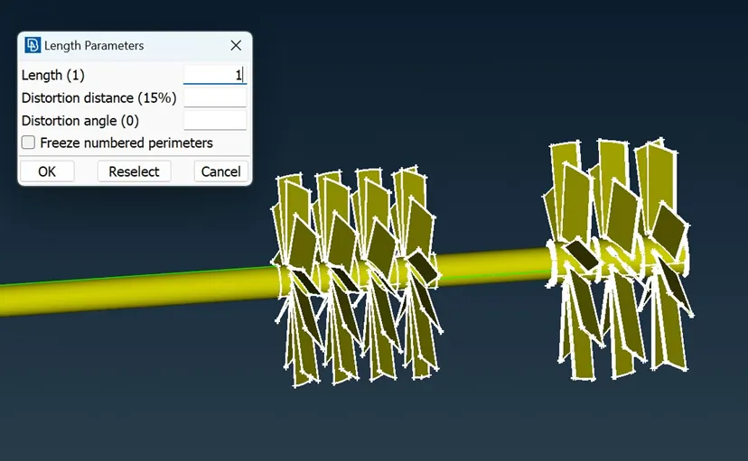
· After giving the length of the mesh we can mesh the both blades.
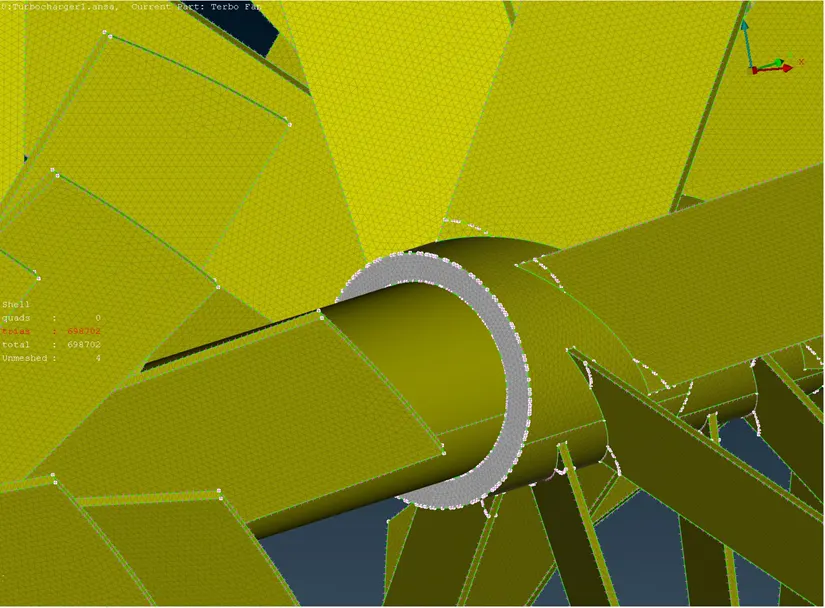
· Here we can see mesh of the both blades are meshed perfectly.so now we can move on to the next part to mesh.
3. Impeller
Impeller = Target length 2mm
Quality criteria
Minimum Target Length = 1
Maximum Target length = 3
Mesh Parameters
Target length = 2
Minimum Target Length = 1
Mesh Type = Tria
· Select the Mesh module button à Parameters à length à Perimeters
· Drag the cursor to the blades and select both the blades, now click on the middle mouse button and give the mesh value size as 2mm.
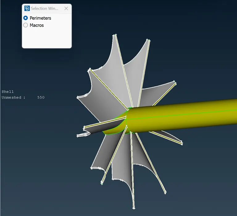
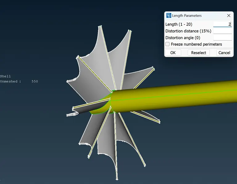
· For the perimeters the length of the mesh is given the value of 2mm.
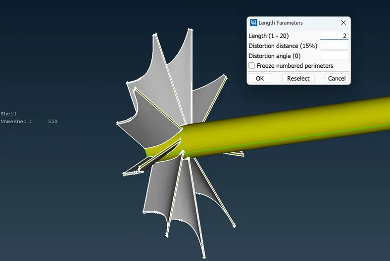
· In here in Macros we select the Impeller by using box selection tool and give the value of 2mm in the Length of the mesh.
· After giving the value in the Perimeters and Macros in the mesh length, we can mesh the Impeller by using spot mesh à Visible.
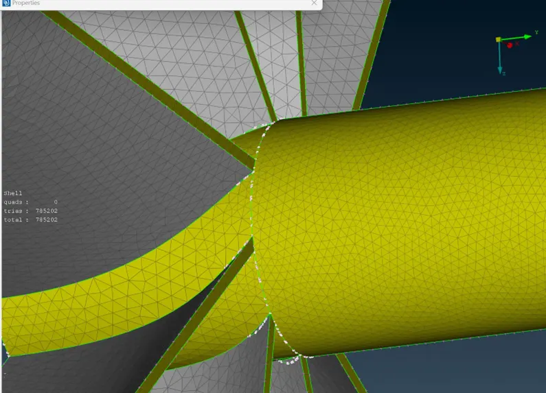
· We can see that the place where the shaft meets the component having different target length. The mesh adapts such that there is a connectivity between the two components.
4. Shaft rotor
Shaft rotor = Target length 1mm
Quality criteria
Minimum Target Length = 0.5
Maximum Target length = 2
Mesh Parameters
Target length = 1
Minimum Target Length = 0.5
Mesh Type = Tria
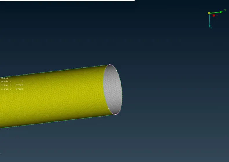
· Select the Mesh module button à Parameters à length à Perimeters
· Drag the cursor to the shaft and select both the shaft, now click on the middle mouse button and give the mesh value size as 1mm.
· After selecting the values in the Perimeters and Macros of the mesh length we can mesh the shaft.
5. Turbo charger
Turbo charger = Target length 5mm
Quality criteria
Minimum Target Length = 3
Maximum Target length = 7
Mesh Parameters
Target length = 5
Minimum Target Length = 3
Mesh Type = Tria
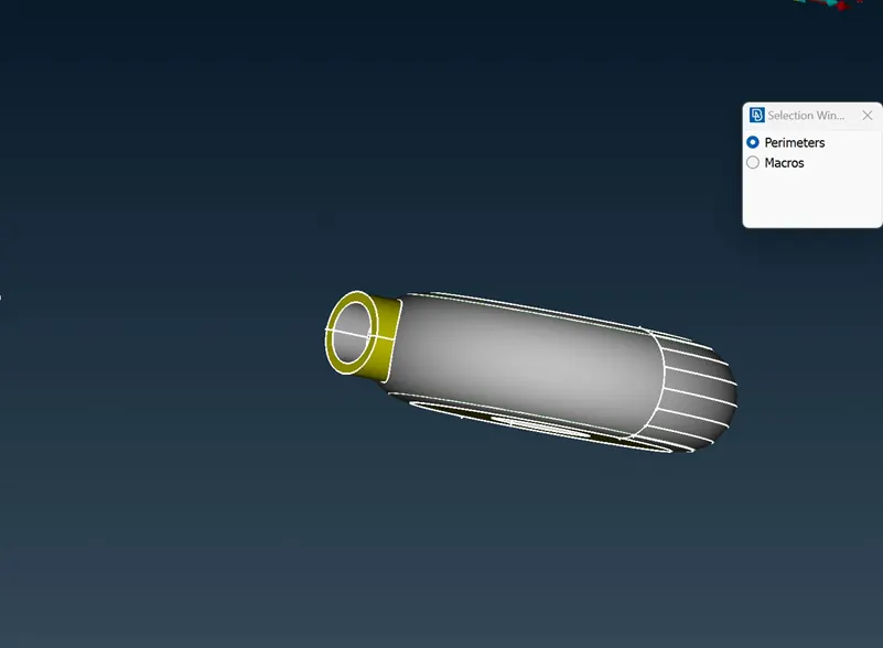
· Select the Mesh module button à Parameters à length à Perimeters
· Drag the cursor to the Casing and select, now click on the middle mouse button and give the mesh value size as 5mm.
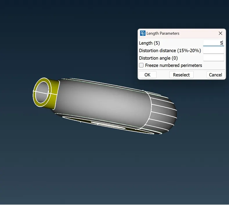
· In the image we given the value of 5mm mesh in the Perimeters.
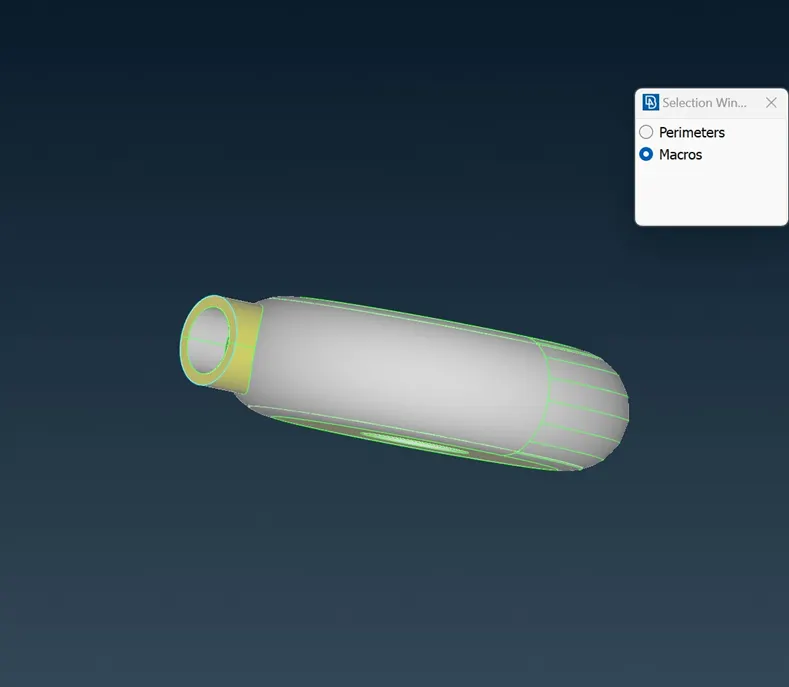
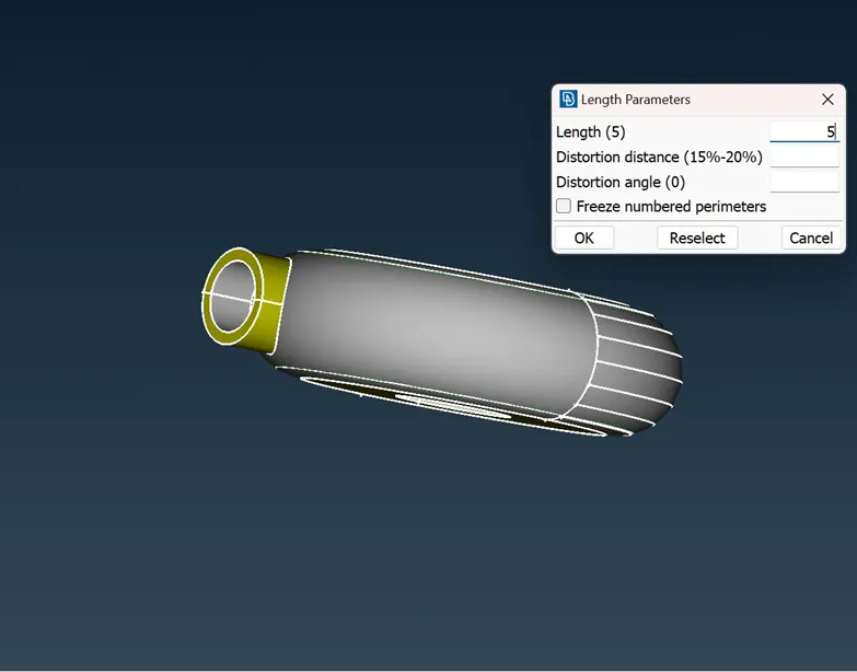
· The Macros have been selected and given the length parameters of 5mm. Now we can mesh the turbo casing.
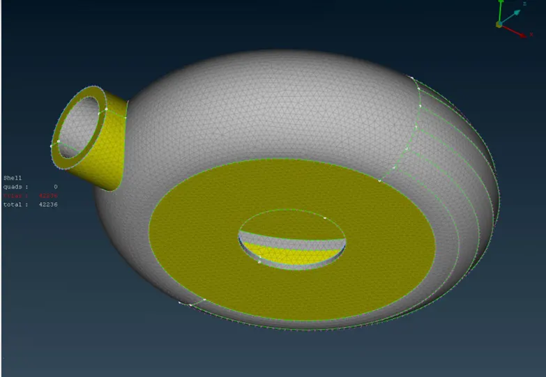
· The turbo casing is meshed with 5mm.
6 . Meshing the Compressor Casing
Compressor casing = Target length 5mm
· We need to mesh up the each of the body part individually as per given value.
· Before meshing the body parts we need to assume the mesh length and target length as given. For that we first the give values minimum length and maximum length in the Quality criteria.
· In the below image shows that the values are given minimum length 3 and maximum length 7 for the Compressor casing.
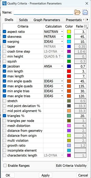
· After giving the value for the minimum and maximum length in the Quality criteria, now we need to give the value in the Mesh parameters.
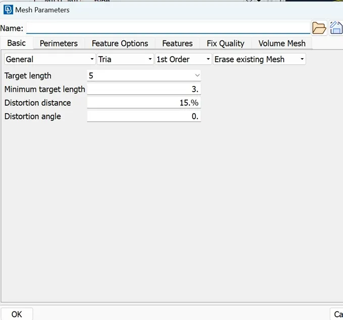
· The Target length for the compressor casing is set upto 5mm and and give value for 3 in the minimum length just like we give in the Quality criteria.
· After setting up the values in the Mesh paramters and Quality criteria we need to give the values for the Perimeters and Macros.
For that select the MESH module button à Parameters à Length.
· Drag the cursor to cover the entire model and click middle mouse button to give the size as 5mm for entire model.
Perimeters
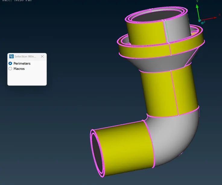
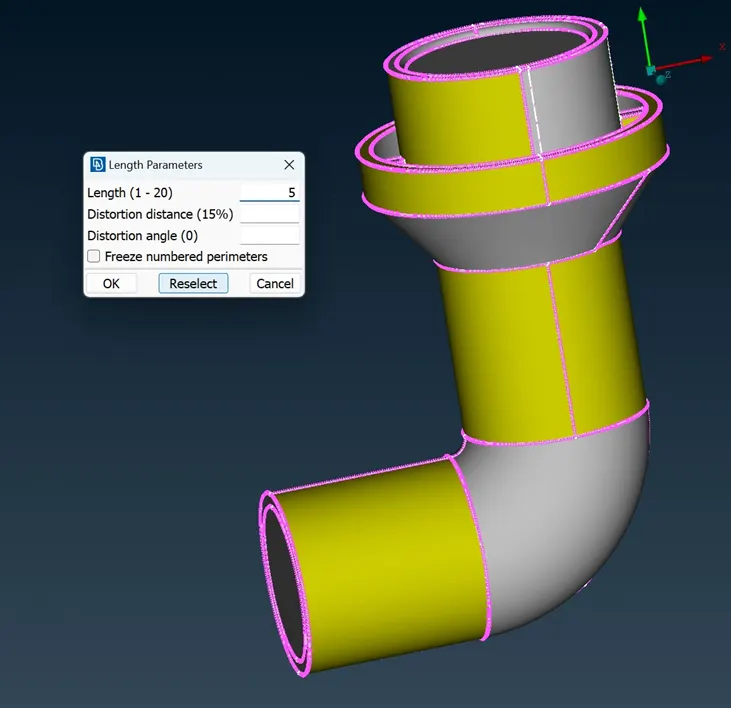
· In the below image the lengths is given as 5mm and click on OK. So after giving the values of length in the Perimeters, the same procedure to give the values of length for the Macros.
Macros
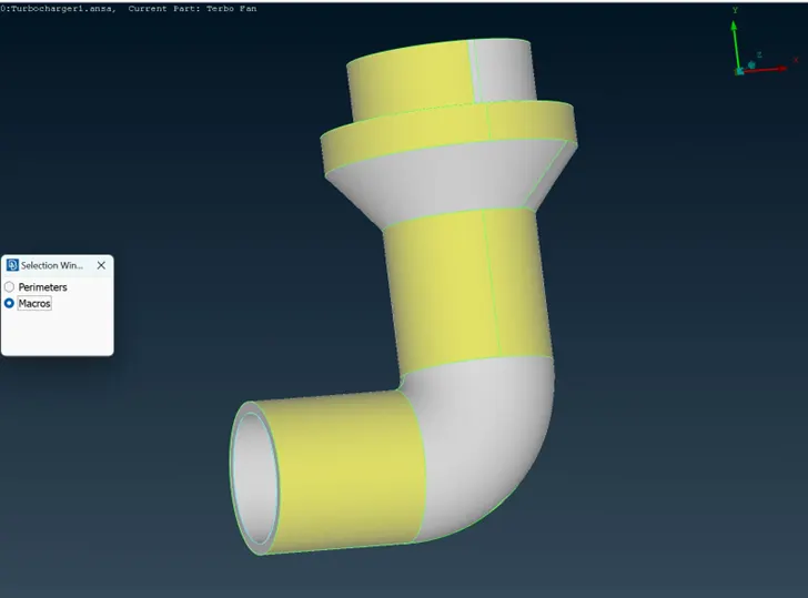
· In here we select the entire model by using box select tool in the Macros and assume that the value of the length is 5mm.
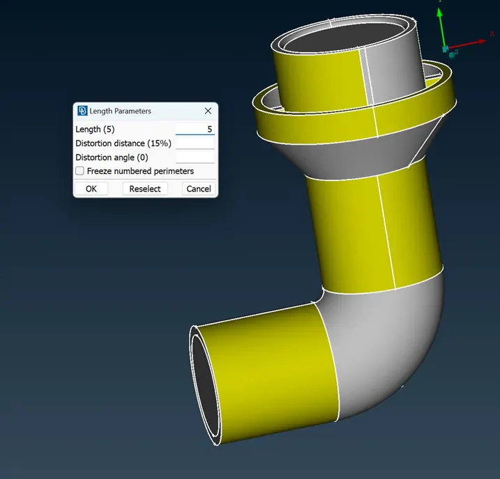
· After giving the values of the length, now the model is ready for meshing.
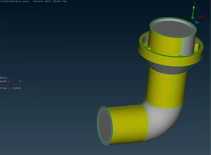
· After giving the values of the length, now the model is ready for meshing.
· Here we can see the 5mm meshed surface of the model. Now we can mesh the other body parts just like these procedures.
7. Turbo casing & Inlet casing cover
· The same procedure for this required as follows and the Mesh parameters and Quality criteria are same, no need to change it.
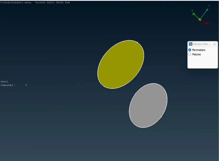
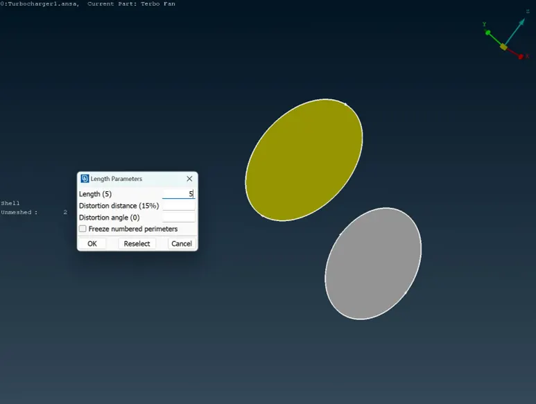
· Here we can give the value of length 5mm for the Inlet and Outlet in the Perimeters.
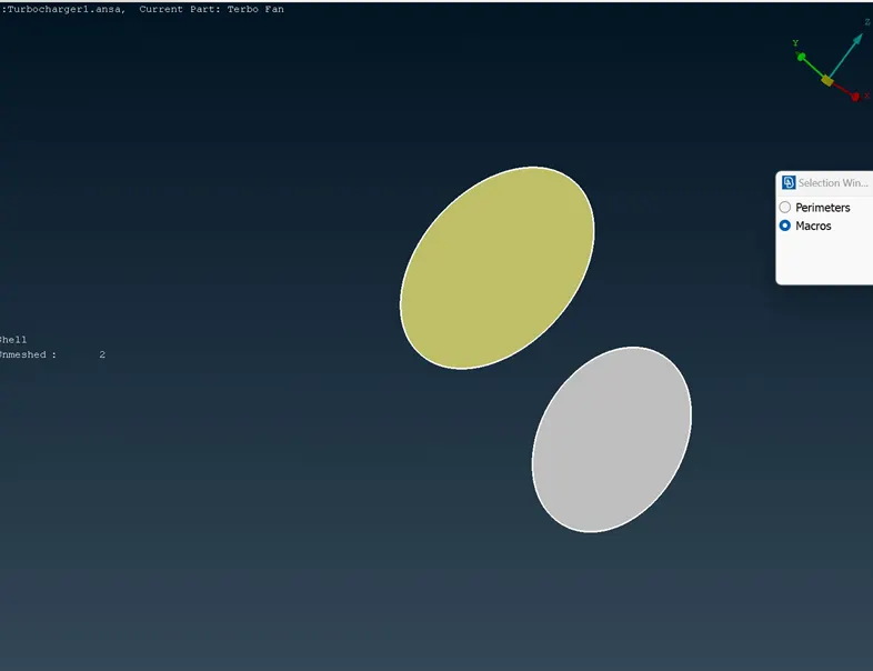
· Here the Inlet and Outlet are selected.
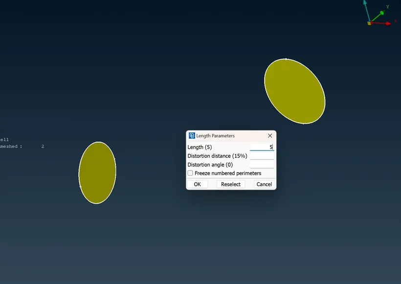
· Here we can give the value of length 5mm for the Inlet and Outlet in the Macros.
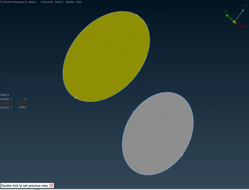
· It shows that the Inlet and Outlet are meshed.
After the surface meshing the each of the PID’s of the model, now we can go to the volumetric meshing the model.
Volumetric Meshing:
· After the surface meshing is done, we can now achieve volume meshing. Ensure that the model is free from any geometric errors and is appropriately scaled.
· Pay close attention to the quality of the volume mesh. Check for element disortions, skewness, and aspect ratios, aiming for a well-balanced and high-quality mesh.
· Define the material components for the components, under the volume meshing choose define and select the whole db in the popup window.
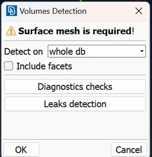
· After selecting whole db model in volume detection. The volume popup window will open.
· In that we can see the various volume present in the geomentry, we can delete the unwanted ones and keep the necessary volumes where the fluid can possibly flow in geomentry.
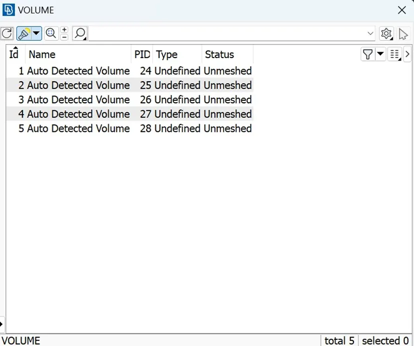
· This image shows unwanted surface model in volume are needed to checked and deleted.
· After deleting the outer thickness volume and only keeping the fluid volume region, we can remesh each volume using the tetra using the Tetra CFD option under the mesh.
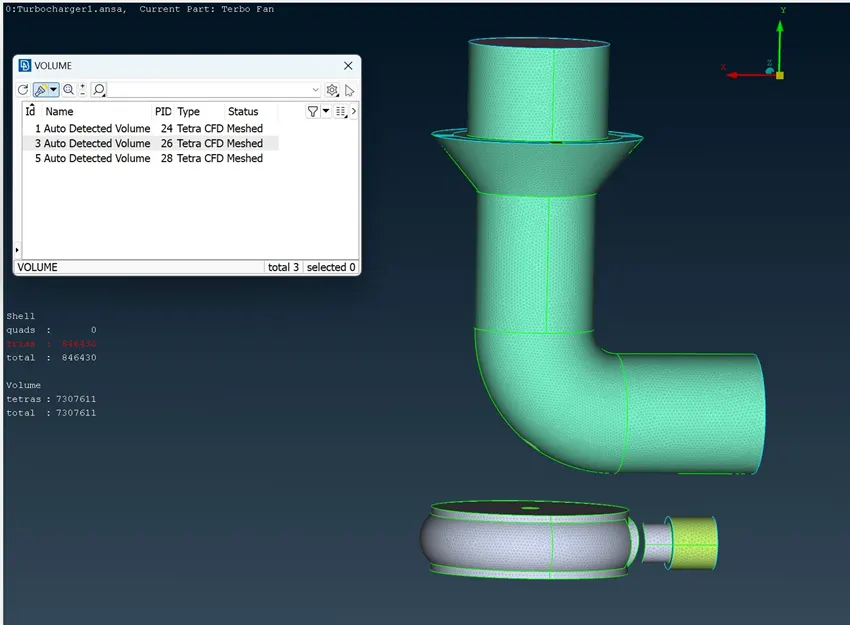
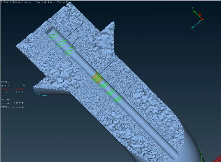
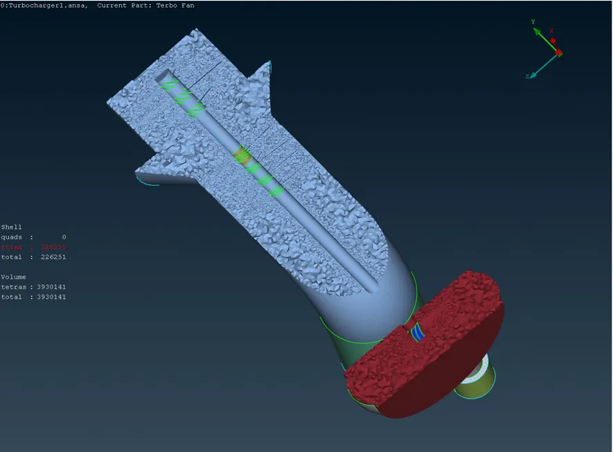
· After meshing the each of the volume is remeshed, the volume mesh can be viewed for each component.
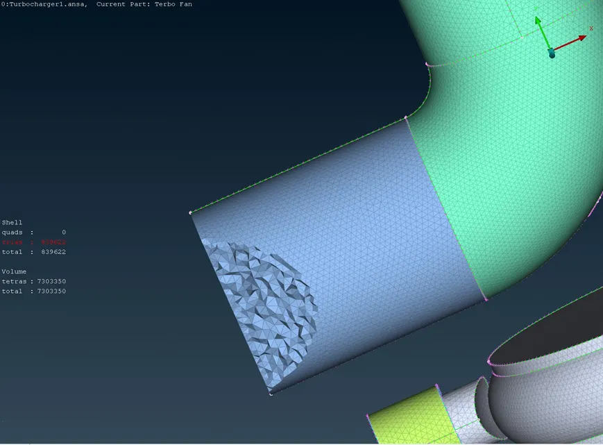
· The volume mesh has been created for each volume and cut section to view the 3D mesh.
Results:
https://drive.google.com/file/d/1i2ODPCBiJybO2kRubiN36mtKYMsa4_0n/view?usp=sharing
Conclusion:
The process of preparing the turbocharger model for CFD analysis required attention to detail. We began by thoroughly addressing geomentric errors within the model to ensure its intergrity. Accurate volume assignment and Property ID (PID) allocation followed, forming the basis for our meshing procedures.
Surface meshing was carried out in adherence to specified target lengths. Blade stage-1, Blade stage-2, shaft rotor, and Impeller were meshed at 1mm, while Turbo casing, Compressor casing, and Inlet casing cover we set at 5mm.
Subsequently, volumetric meshing converted the surface mesh into a 3D volumetric mesh, capturing the turbocharger’s internal surface. The mesh was optimized for both precision and computational efficiency.
In conclusion, this comprehensive process, overcoming geomentric errors and optimizing meshing, has the potential to enhance the efficiency and reliability oof the turbocharger, contributing to automotive technology advancements.