Week 3 Challenge : CFD meshing on Turbocharger
CFD Meshing on Turbocharger using ANSA
Objective:
For the given model 3D model, the following steps are required:
1. Geometrical Check:
- Conduct a thorough geometrical examination of the model to identify any errors or discrepancies.
2. PIDs Creation and Assignment:
- Create and assign PIDs (Property IDs) to different components of the model for effective organization and management.
3. Surface Mesh Generation:
- Generate surface meshes for the model based on the specified target lengths as per the assigned PIDs.
- The target lengths for different components are as follows:
- Blade stage-1: 1 mm
- Blade stage-2: 1 mm
- Impeller: 2 mm
- Shaft rotor: 1 mm
- Turbo casing: 5 mm
- Compressor casing: 5 mm
- Inlet casing cover: 5 mm
4. Volumetric Meshing:
- Perform volumetric meshing for the required volumes within the model.
- This step involves creating mesh elements in the three-dimensional space to accurately represent the fluid flow and analysis requirements.
Table of Contents:
- Topology Clean-up
- Assigning PIDs
- Surface Meshing
- Volumetric Meshing
- Conclusion
I. Topology Clean-up
The initial step involves the identification and resolution of individual inconsistencies by generating new faces to patch them. To accomplish this, follow these instructions:
1. Navigate to Tools > Checks > Geometry in the menu.
2. Select the appropriate names or entities required for the process.
3. Click the Execute button to initiate the geometry check.
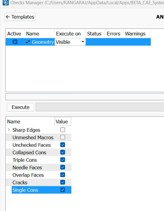 |
After Executing the check, we can view those Single CONS and Triple CONS.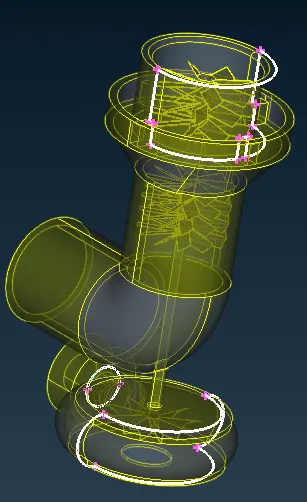 |
4. Ensure that we are in the Topology module. Our objective now is to remove the Single CONS and Triple CONS (excluding the necessary Triple CONS).
5. Access the Utilities menu and choose the Delete option.

6. Opt for the Views menu and select the PID view option. This view is based on PID Regions. During the model import process, ANSA automatically generates certain PID regions. Remove any unwanted PID regions from the model. This action may eliminate some Single CONS. (Press CTRL-Shift to check for Single CONS/Triple CONS)

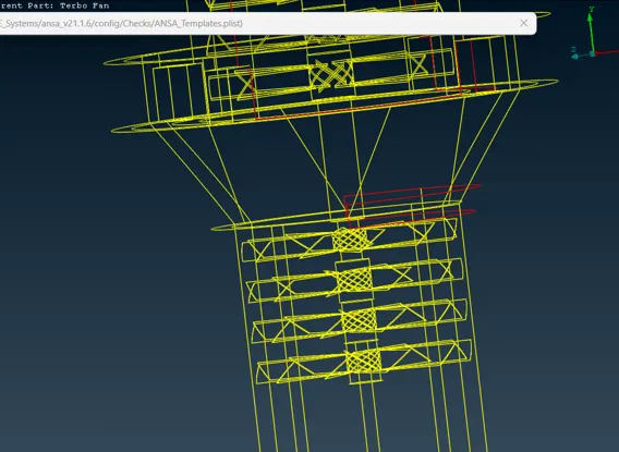
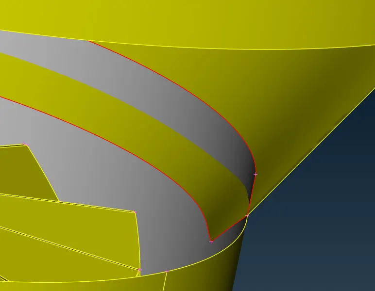
7. At this point, you will observe surfaces with Single CONS issues. To address these cases, utilize the Modules Buttons > Faces > Intersect option. This will prompt a dialog box with two options (groups): First and Second. Select the faces to be grouped as 1st and 2nd for the intersection. The dialog box will then inquire which face areas should be deleted. Retain the necessary faces and delete the others.
 |
 |
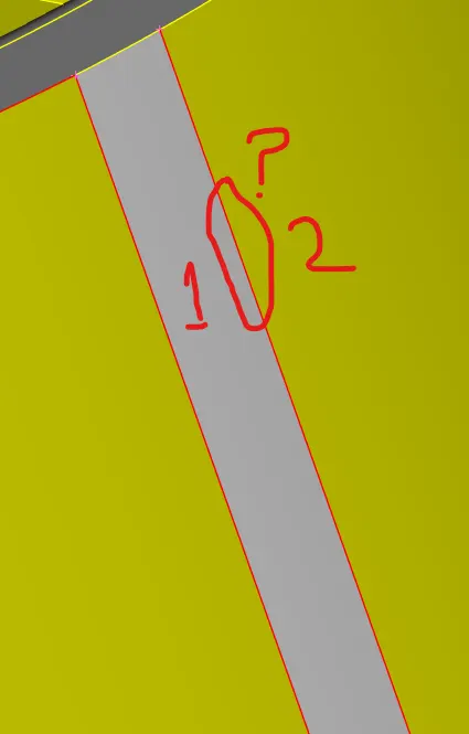
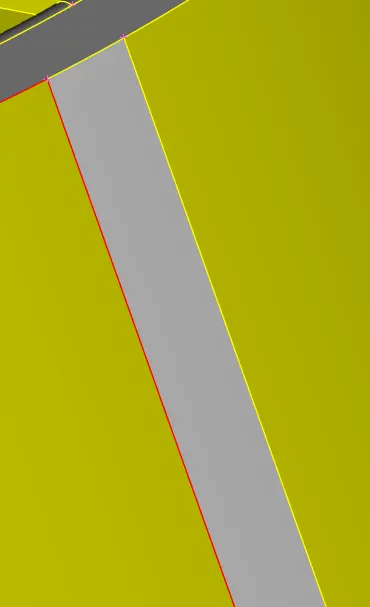
8. Occasionally, we may encounter a scenario where Single CONS persist even after creating new faces, indicating that the CONS are shared by 2 faces.
Go to Modules Buttons > CONS > Paste option. Select the CONS to paste.
 |
 |
9. To address the single CONS shown in the image below, it is not possible to directly create surfaces. Instead, we need to generate Hotpoints along the curved single CONS, as illustrated in the image.
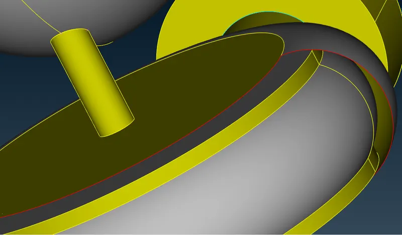
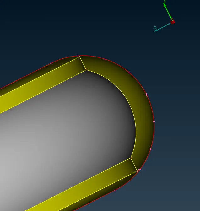
10. Proceed to create new faces by individually selecting the entities. Click the Middle Mouse button and confirm by clicking OK.
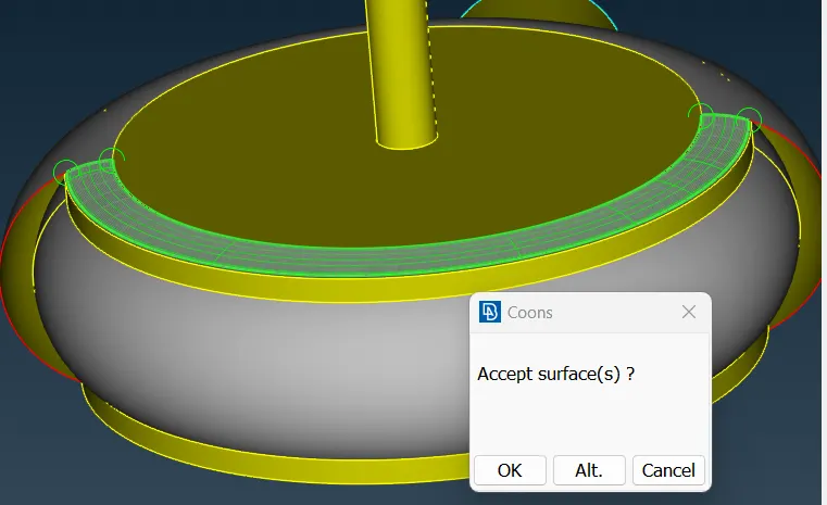
11. Our model contains one necessary Triple Cons, which cannot be deleted.
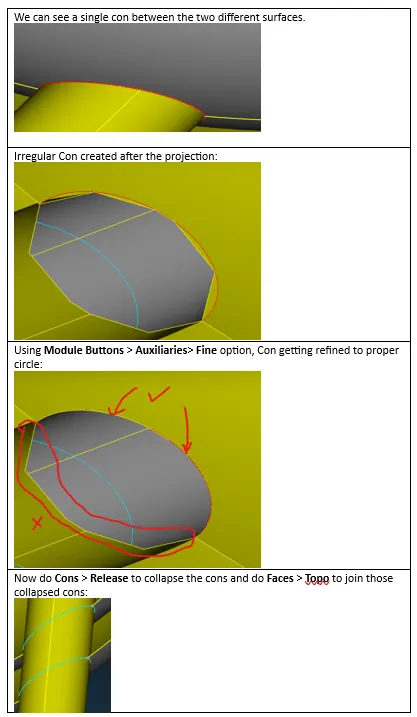
12. Perform a visual inspection for any additional surfaces, even if they have double cons. During this examination, an unwanted surface was identified. Delete the surface and project the CONS onto the Shaft surface.
Two Cons are now created: one for the inner case (top) and another for the outer case (bottom).
The newly created Cons may appear irregular. To address this, access Modules Buttons > Auxiliaries > Fine option. Apply the Fine option by continuously clicking on those Cons to refine their appearance.
II. Assigning PIDs
In order to perform CFD analysis, it is crucial to close the domain. This enables the development of high-quality surface and volumetric meshing in the subsequent stages.
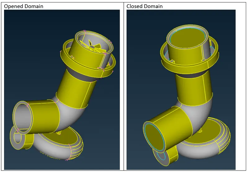
Note: In the image on the right side above, multiple triple cons are visible after generating the new surfaces. It is important to note that these triple cons are necessary and should not be considered as errors.
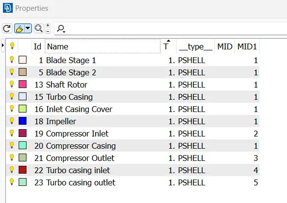
Next, we need to assign PIDs. To do this, navigate to the Properties section. ANSA automatically generates some PIDs based on the domain model. We have the option to rename the necessary PIDs and delete the rest. Additionally, we can create new PIDs as needed to meet specific requirements.
Creating, modifying, and applying PIDs:
1. Access the Properties database to view the automatically generated PIDs by ANSA.
2. Creating a new PID:
a. Right-click within the Properties dialog box to open a shortcut menu. Select New > PSHELL > PSHELL and provide a suitable name for the part.
3. Editing a PID:
a. Right-click on a PID and select Edit. This opens a dialog box where you can make modifications to the existing PID.
or
b. Select a PID in the Properties database and press the F2 button to rename it.
4. Applying PIDs to the model:
a. Right-click on a PID and choose Apply. Then, navigate to the model and select the appropriate model to associate it with the PID name. Confirm the selection by clicking the middle mouse button.
III. Surface Meshing
Switch to the Mesh Module in the software.
The following mesh requirements need to be met:
1. Blade stage-1: 1 mm
2. Blade stage-2: 1 mm
3. Impeller: 2 mm
4. Shaft rotor: 1 mm
5. Turbo casing: 5 mm
6. Compressor casing: 5 mm
7. Inlet casing cover: 5 mm
5 mm Mesh:
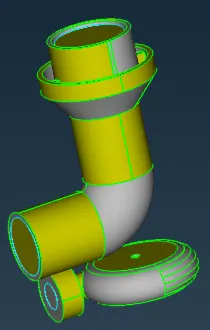
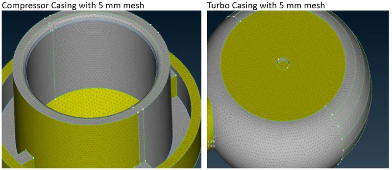
For the components Turbo Casing, Compressor Casing, and Inlet Casing cover, a mesh length of 5 mm is needed.
By utilizing the PID region view tool, we can isolate these specific components and mesh them accordingly with the desired 5 mm mesh length.
1. Access the Mesh Parameters and perform the following actions:
a) Set the Target length to 5 mm. Then, define the Minimum target length as 3 mm and the Maximum target length as 7 mm.
b) Select Tria as the mesh type from the dropdown menu.
c) Click OK to confirm the changes.
2. Proceed to the Quality Criteria section and follow these steps:
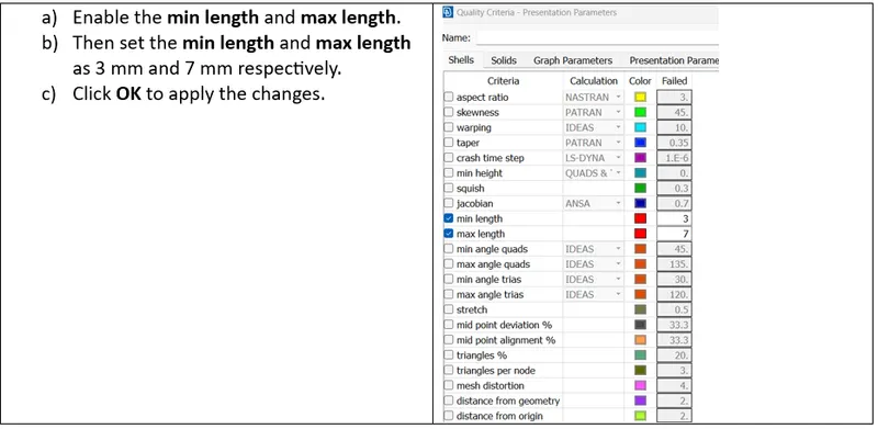
3. Navigate to Modules Buttons > Perimeters > Length option. This action will trigger a small dialog box.
a) Click on Perimeters and use the box selection to choose the isolated components. Then, click the middle mouse button.
b) The Perimeter window will open. Enter the desired length of 5 mm and click OK.
c) Repeat steps a and b for Macros, and click OK.
4. Go to Modules Buttons > Mesh Generation > Spot Mesh option. Apply Spot Mesh to the identified components by utilizing box selection.
2 mm Mesh:
Component: Impeller
Using the PID region view tool, we can isolate the components to mesh with a mesh length of 2 mm.
Follow the same steps as we did for the 5 mm mesh length.
Mesh type: Tria
Mesh length: 2 mm
Minimum Mesh length: 1 mm
Maximum Mesh length: 3 mm
1 mm Mesh:
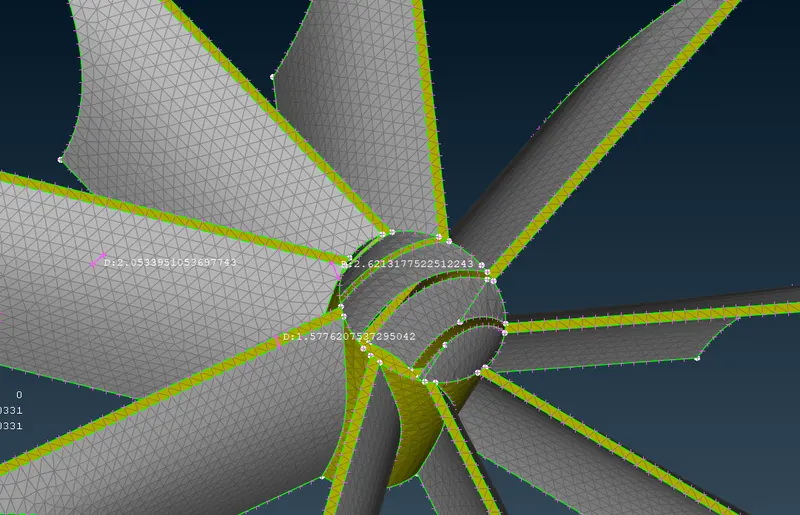
Components: Blade Stage-1, Blade Stage-2, and Shaft Rotor
Using the PID region view tool, we can isolate the components to mesh with a mesh length of 1 mm.
Follow the same steps as we did for the 5 mm mesh length.
Mesh type: Tria
Mesh length: 1 mm
Minimum Mesh length: 0.5 mm
Maximum Mesh length: 2 mm
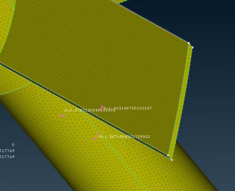
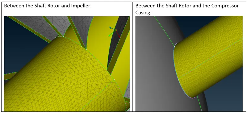
When meshing components with different lengths, it is common to encounter undeveloped mesh surfaces near the interfaces where these varying mesh surfaces converge.
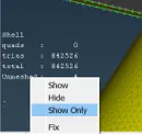
To isolate the unmeshed components, right-click on the Unmeshed option in the Main Window and select Show Only from the shortcut menu. This action will isolate the unmeshed components.
Now, we need to adjust the mesh length ranges (Min and Max) in the mesh settings for the unmeshed components, specifically the Impeller and Compressor Casing.
For the Impeller:
1. Go to Utilities > Mesh Parameters:
a. Set the Min Mesh length as 0.5 mm (due to the presence of the Shaft Rotor with a length of 1 mm).
b. Set the Max Mesh length as 3 mm (due to the Impeller with a length of 2 mm).
2. Go to Utilities > Quality Criteria:
a. Set the Min Mesh length as 0.5 mm (due to the presence of the Shaft Rotor with a length of 1 mm).
b. Set the Max Mesh length as 3 mm (due to the Impeller with a length of 2 mm).
3. Go to Mesh Modules > Perimeters > Length:
a. Ensure that the Perimeters are within the range of 1-2 mm.
b. Check that the Macros are within the range of 1-2 mm.
4. Generate the mesh using the Spot Mesh tool.
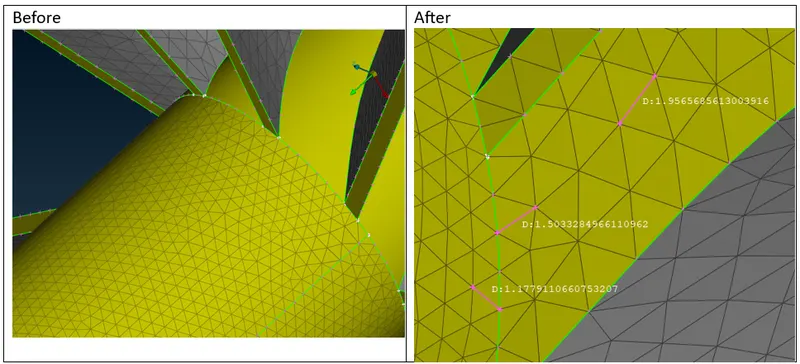
For the Compressor Casing:
1. Go to Utilities > Mesh Parameters:
a. Set the Min Mesh length as 1 mm (due to the presence of the Shaft Rotor with a length of 1 mm).
b. Set the Max Mesh length as 7 mm (due to the Compressor Casing with a length of 5 mm).
2. Go to Utilities > Quality Criteria:
a. Set the Min Mesh length as 1 mm (due to the presence of the Shaft Rotor with a length of 1 mm).
b. Set the Max Mesh length as 7 mm (due to the Compressor Casing with a length of 5 mm).
3. Go to Mesh Modules > Perimeters > Length:
a. Ensure that the Perimeters are within the range of 1-5 mm.
b. Check that the Macros are within the range of 1-5 mm.
4. Generate the mesh using the Spot Mesh tool.
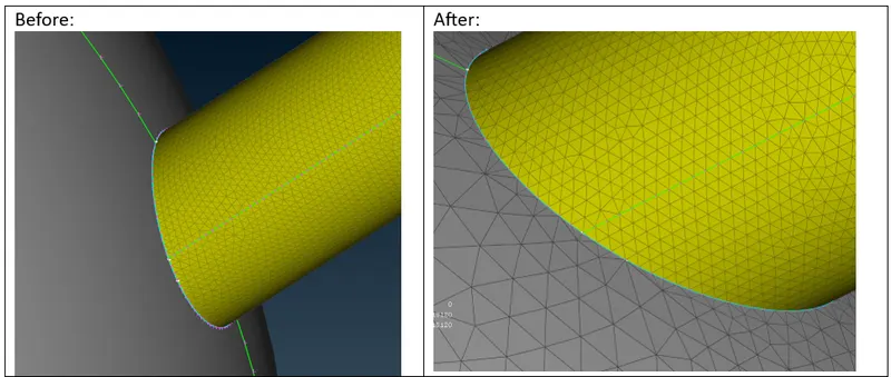
IV. Volumetric Meshing
Navigate to the Volumetric Mesh module and select the Volume > Define option. Perform a long press to view the available options and choose Auto Detect. From the drop-down menu, select the Whole db option and click OK.
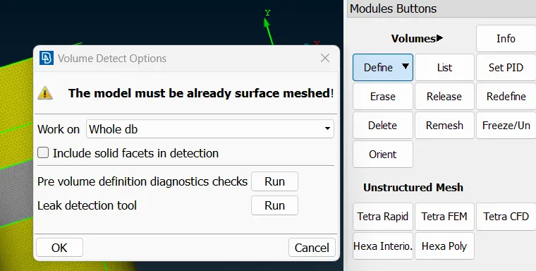
Next, we need to identify the volumes that require meshing. ANSA automatically detects the volumes based on surface meshing and lists them.
For CFD analysis, it is necessary to exclude the thickness volumes. We should focus solely on volumetric meshing for the volumes through which the fluid flows.
The steps to apply volumetric meshing are as follows:
1. Choose any volume from the auto-detected Volume dialog box.
2. Right-click on the selected volume and choose Remesh from the shortcut menu. Then, select Tetra CFD.
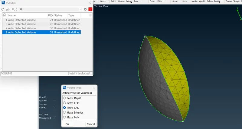
3. Repeat steps 1 and 2 for other unmeshed components.
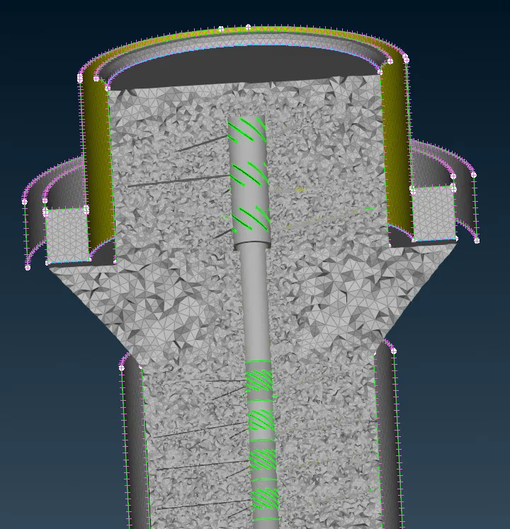
Utilize the view tools (Not icon) to observe the generated volume meshes.
In the vicinity of the blade and shaft rotor, you may notice small volume mesh elements. As you move farther away from these components, the volume mesh becomes larger in size.
V. Conclusions:
In conclusion, the following steps were performed to analyze the given model:
1. Geometrical Check: A thorough examination of the model was conducted to ensure its geometrical accuracy.
2. PIDs Creation and Assignment: PIDs (Property IDs) were created and assigned to different components of the model, enabling better organization and management.
3. Surface Meshing: The surface meshing process was carried out using target lengths specific to each component based on their respective PIDs. The target lengths were as follows:
- Blade stage-1: 1 mm
- Blade stage-2: 1 mm
- Impeller: 2 mm
- Shaft rotor: 1 mm
- Turbo casing: 5 mm
- Compressor casing: 5 mm
- Inlet casing cover: 5 mm
4. Volumetric Meshing: Volumetric meshing was performed for the required volumes in the model, focusing on regions where fluid flow occurs.