Week 3 Challenge : CFD meshing on Turbocharger
Report on Week 3 Challenge : Turbo-Charger Mesh
B A Mayur
Aim: Surface mesh of a turbo charger based on the required target length.
Theory:
Tria elements are polygons having 3 sides (edges) and 3 vertices. They are elements formed with 3 nodes. The element size is specified using the meshing tools. A model is imported and steps are followed to generate the surface-volume mesh for the model of a certain geometry, here, the model being a turbo charger.
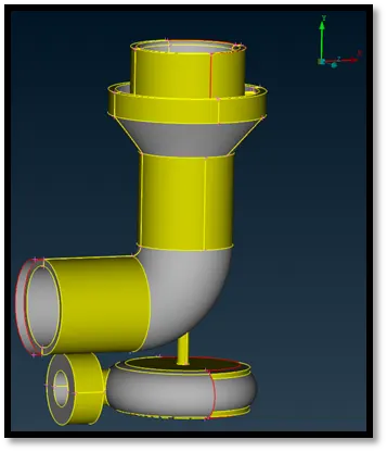
Fig: Turbo charger model
Procedure:
Import turbo charger model
The turbo-charger model is first imported into the ANSA environment (v23.1.0) for topo clean-up. Using the ‘Topo’ option, we can check for overlapping surfaces marked with blue edges having triple cons.
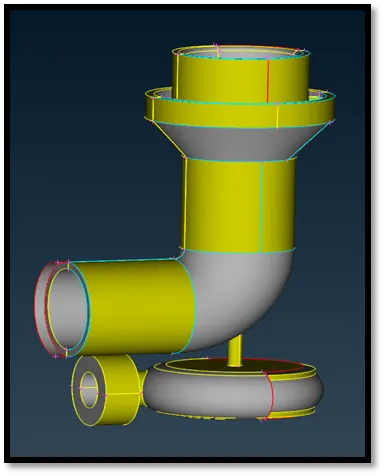
Fig: Triple cons (blue edges) – Topo clean-up for overlapping surfaces
The steps are followed to avoid single cons and overlapping surfaces to remove red and blue edges respectively. Using the ‘Delete’ option, the entire overlapping surface is taken off as it is not necessary. The open surfaces are patched using the ‘Fill Hole’ option. If the approach fails, the ‘Multi-Project’ tool is used to project multiple hot points to create the surface alignment with respect to the surface edges and the model surface is closed using the ‘COONS’ option and confirming after looking at the preview of the new surface to be created.
Firstly, close to the compressor section at the bottom, the extra edge is deleted.
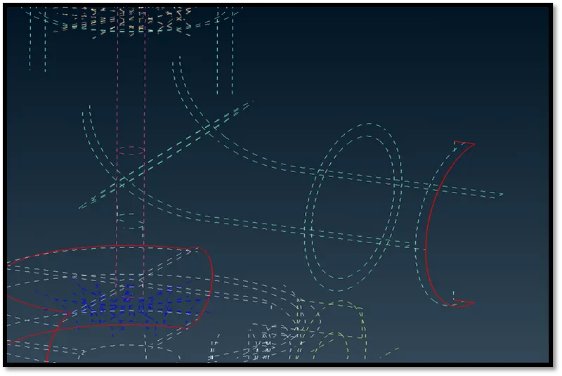
Fig: Extra Edges are to be removed – Wireframe view support to find them
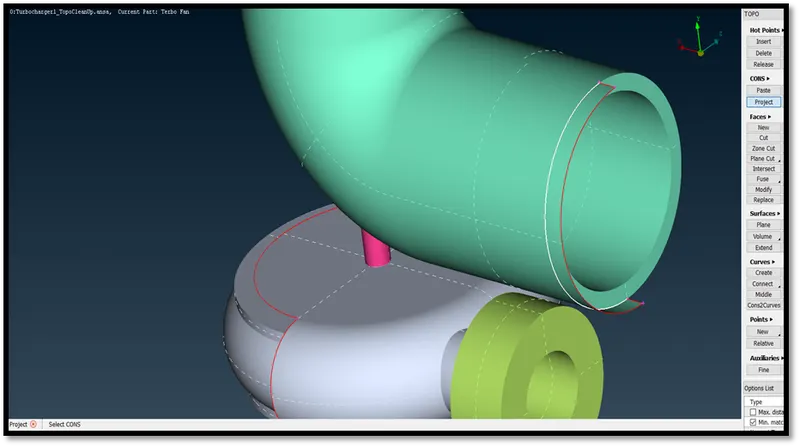
Fig: Project CONS option to create a con on the curved surface
The CONS -> Project option helps to select the con and then the face so that a new con can be projected with the information of the con and face. This way a con is created at the thickness and extended surface region. The ‘Delete’ option is selected to delete the extended face.
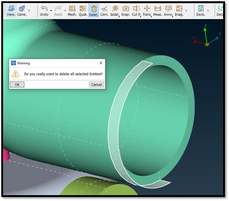
Fig: Extended face can now be deleted
The new con created using the ‘Project’ option can now serve as an edge to the extended surface which can be deleted.
At the top part of the model, there is an open surface which must be closed.
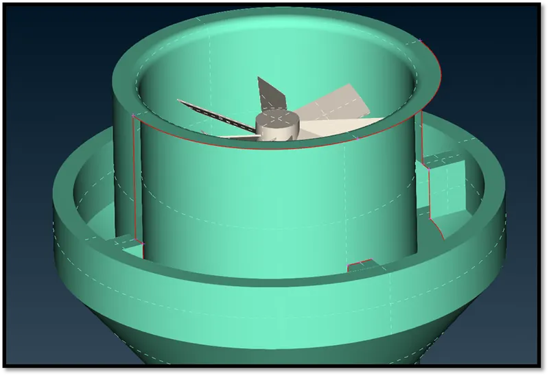
Fig: Turbine section (top part)
The Faces -> New -> COONS option is chosen to mark the single cons and fill the surface using the alternate option as needed.
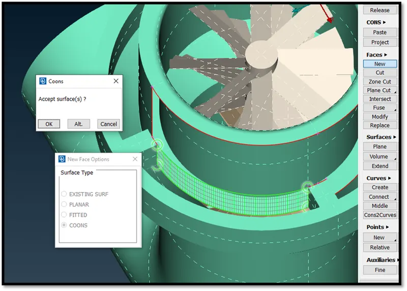
Fig: Surface created near top part
The same method is used to fill the remaining open patch to create the fill.
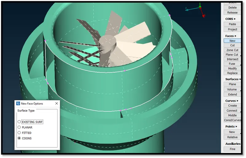
Fig: COONS option to create surface fill
The same method is used to complete the surface fill to close the model
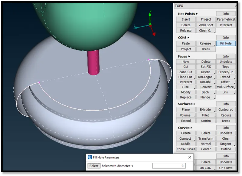
Fig: Fill Hole option to close the compressor casing
The casing is now closed using the Fill Hole option. No hot points were needed to be created and the surface was closed smoothly. If the method fails, hot points can be created at certain lengths on alternate edges of the curve and the surfaces can be filled with reference to respective sets of hot points.
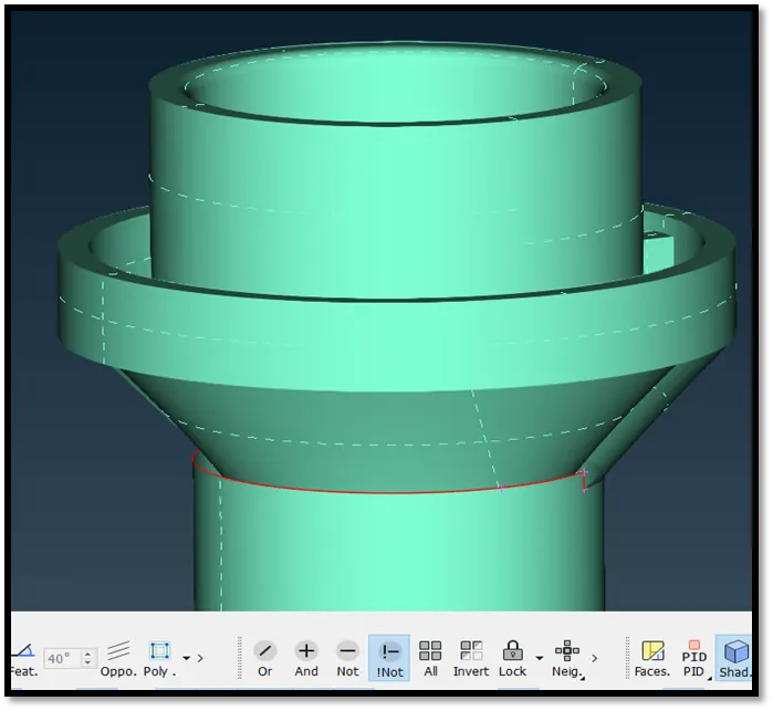
Fig: !Not option selection
!Not option is used to show only the area of interest, the scope of the work can only be seen.
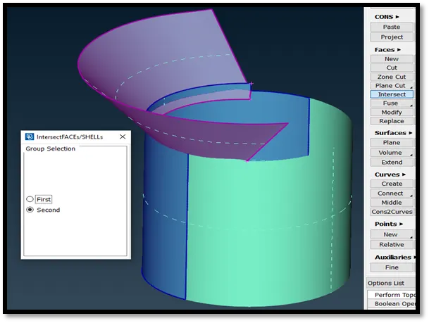
Fig: Intersect option to create a con at intersection of two planes
There is an intersection and extra surface present after the intersection of the inclined and curved surfaces. A new con is created at the intersection and the extra surface is deleted to convert the triple con to double con
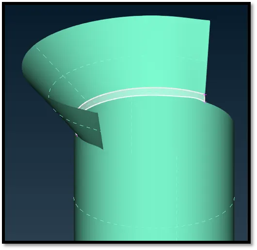
Fig: Extended surfaces are deleted.
As the progress is towards making the shaft as one volume component, near the compressor section, there can be a face projected to delete the surface.
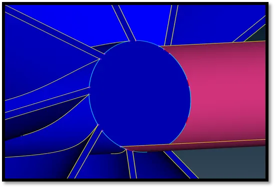
Fig: surface is attached to the fins
Under CONS -> Project option is used to project the circumference of the pink body onto the blue body and thus the face can be selected to be removed.
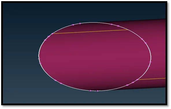
Fig: Circumference of CONS of pink body is selected to be projected
These edges are now projected onto the blue surface. The surface can now be deleted.
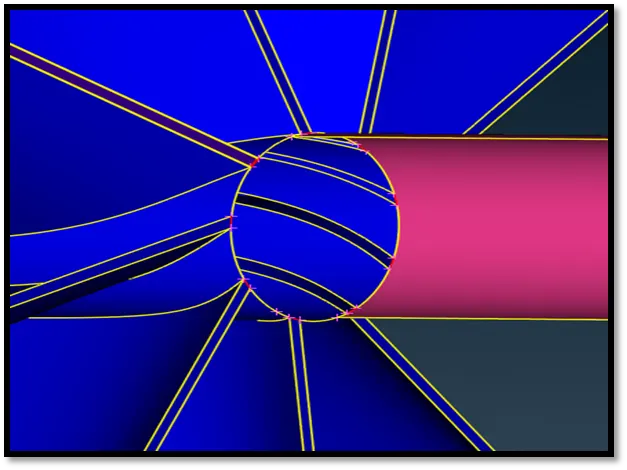
Fig: Surface deleted
A geometry check is evaluated to examine the model for errors and unwanted openings. The PIDs are assigned later (namings) for the volumetric mesh. Making sure that the model is closed is a good practice.
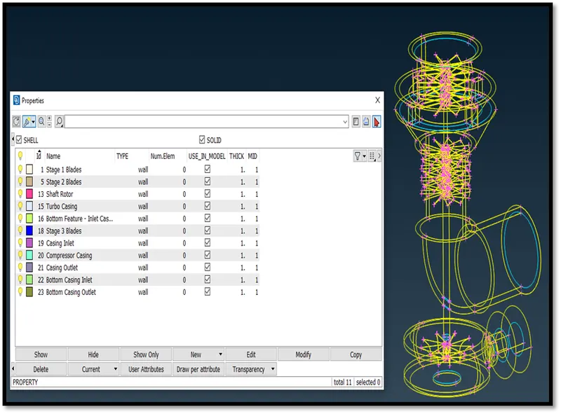
Fig: Closed model (with PID naming)
The geometry checks have been performed and no errors have popped. This is a good indication that the model can be used to proceed for surface and volume meshing.
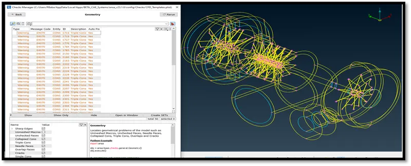
Fig: No errors on geometry check
The model has no red edges (single cons) and only the double and triple cons are visible. The warnings display the same messages/information and they are shown because of the creation of the inlet-outlet surfaces, done for ensuring a closed volume space/domain for simulation purposes.
The model is now ready for surface meshing followed by volumetric mesh operation. The compressor body with inlet and outlets are meshed.
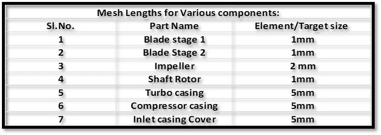
The procedure calls for isolating each model/component and assigning the respective quality criteria for meshing to complete the operation.
The compressor casing is meshed with a mesh length of 5mm.
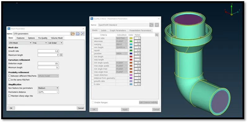
Fig: Mesh Quality Criteria and Mesh Parameters Settings
The minimum and maximum mesh element sizes are specified as 3mm and 7mm respectively. The perimeter length and macros by selecting the compressor casing with inlet and outlet are set to 5mm. Spot mesh operation gives a mesh of 5mm to the component as shown in the below figure.
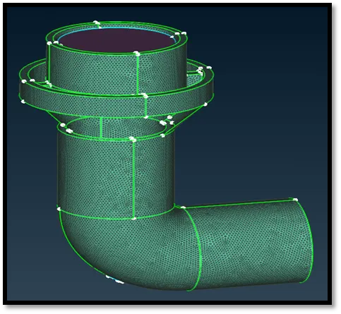
Fig: Compressor Casing Mesh
The image also shows the meshing performed internally, relative to the outer surface.
The turbo casing is now approached for surface meshing. The same method is followed for all other components and lengths are specified according to the mesh element size given in the above table for all components. The inlet casing is meshed along with the turbo casing as both of them can be meshed with same mesh lengths of 5mm.
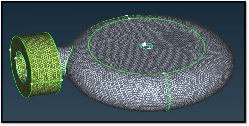
Fig: Turbo casing and inlet casing cover
The inlet and outlet of the turbo casing are done in the same way. They are isolated and meshed for 5mm mesh lengths.
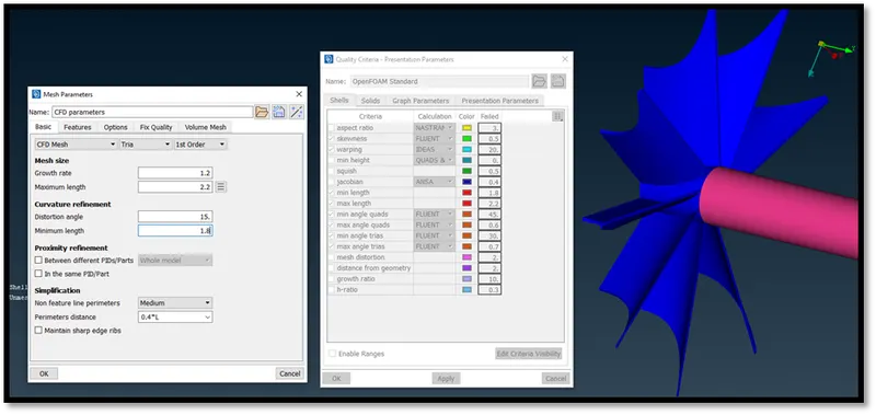
Fig: Impeller - mesh settings
The impeller is meshed with a mesh element target size length of 2mm. The minimum and maximum lengths are specified as 0.5mm and 3mm respectively.
For the blades and shaft the maximum and minimum lengths are specified as 1mm and 5mm respectively under mesh parameters and mesh quality criteria.
The shaft and blade stages have a mesh element target size length of 1mm. The operation is performed together for the mentioned components having same mesh element lengths. A cut option can be performed around the triple cons where there is a change of mesh sizes if necessary. However, ANSA will suffice the mesh generation algorithm to continually mesh between surfaces will a gradual change od mesh lengths between regions. The image shows a complete surface mesh performed.
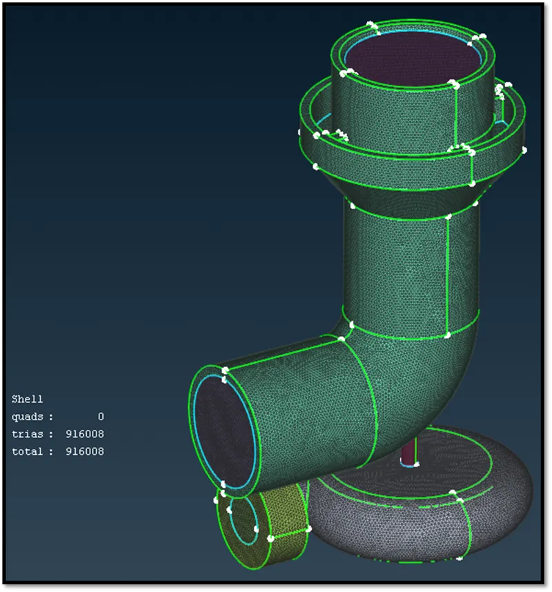
Fig: Surface meshing of all components
The model can now be used to complete the volume meshing of the enclosed space within components to establish the fluid domain. The volume meshing is not considered for the thickness of the solid material, but only for the space where the fluid may flow. In the Volumes -> Define option -> Volume Detect option -> Whole database option enables selection og the complete assembly for volume meshing.
The image shown below is depicting all volume and thickness regions. The thickness regions are avoided (deleted) and only volume spaces can be used to work upon for volume meshing.
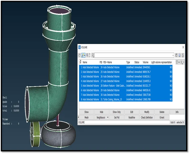
Volume Mesh -> Define -> Whole Database
The thickness components of the parent geometry are deleted. The space for volume domains are kept for volume meshing.
Learning Outcomes:
The tetra mesh is obtained. The mesh elements have adjusted to the volume space against the thickness space where the mesh element lengths have adapted to the geometry for better mesh quality by specifying the mesh criteria. The space around the blades has been taken up by the solid. Hence the volume space close to the gaps have a finer mesh and as the distance progresses away from the solid domain, the mesh criteria takes cares of the mesh element size which was mentioned as 5mm for the outer casing. The impeller and shaft mesh element sizes are 2mm and 1mm respectively. The tria elements generated from the surface meshing for all components have helped to generate the tetra elements for volume meshing. The transition between different mesh element sizes which share a common edge (impeller blades and shaft) have a smooth change of mesh element sizes. The topo clean-up followed by surface meshing and volumetric meshing helps to neatly arrange the assembly for a simulation to obtain precise results with lesser computational time.
Result:
The components obtained can now be run for a flow simulation to check the velocity, pressure and temperature coefficients, plots and contours. The mesh criteria helps for a smoother simulation as there were no errors obtained, the other checked and removed for corrections.
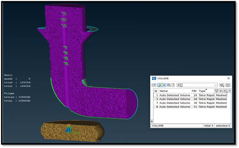
Fig: Volume mesh cut section
Based on the computational specifications, time will be taken to generate the volume mesh for the 4 enclosed volume spaces. We can right click on any of the component and select ‘Mesh’ to perform the volume mesh operation.
Conclusion:
The model assembly was checked for each component for the topo clean-up followed by the surface and volume meshing. ANSA environment provides fruitful tools and methods to view, analyse, and change to obtain a clean mesh model as shown in the results section. This can now be used to perform operations where the volume domain can be utilized for fluid flow simulations and efficiency of the turbocharger.