Week 3 Challenge : CFD meshing on Turbocharger
AIM: To mesh the components of the turbocharger with different mesh cell sizes
PROCEDURE:
STEP 1:Topology Cleanup
- Delete the surface under the compressor casing.
- Create the surface at the inlet of the compressor casing by using the fitted option in the new face tab.
- Create the surface on the turbo casing by creating hotspots using a parametrical option and coons.
- At the outlet of the compressor casing delete the extra surface using the delete option by creating the triple con using the project tool.
- At the curvature of the compressor casing there is an overlapping of the surface, delete it by using intersect and delete options.
- hence all the single cons in the model are converted to double cons we now assign the PIDs to the model.
STEP 2:Settings the PIDs
Assign the pids to the model in the properties tab to:
- blade stage 1
- blade stage 2
- shaft rotor
- turbo casing
- inlet compressor casing
- compressor casing
- impeller
STEP 3:Converting the individual entities into volumes-
- Convert the individual entities into separate volumes by using topo and cut tools.
- Delete the required entities and overlapping surfaces to make the volumes.
- Project the cons by using the project option.
STEP 4:Compress the model
Before meshing, compress the model in order to delete the unwanted faces, nodes, points empty parts, and PIDs
STEP 5:Meshing(creating 2d mesh):
Mesh the model by using the free mesh tool using the element shape as tria.
The mesh length for different PIDs are
- Blade stage 1:1mm
- Blade stage 2:1mm
- Shaft rotor:1mm
- Impeller:2mm
- Compressor casing:5mm
- Turbine casing:5mm
- Internal Compressor casing:5mm
After meshing due to the difference in the mesh lengths at the intersection of the shaft rotor with impeller and compressor casing and turbo casing at that intersection points the mesh is not accurate. Create the hot points at the intersection and cut the area with a length of 3 units. The mesh at the intersection will transfer from 5mm to 1mm gradually.
STEP 6: 3D MESH(Creating volumetric mesh)
After completion of the surface mesh in order to create the volumetric mesh. Create the volumes at the openings. Assign pids to them and mesh them. the volumes that are created are:
- inlet compressor casing
- outlet compressor casing
- inlet turbine casing
- outlet turbine casing
The model is ready for 3d meshing. Get into the volumetric mesh option and perform the volume-detecting option. 8 volumes will be created. Delete the unwanted volumes.
Now enable the 3D mesh or volumetric mesh by using the unstructured mesh using tetra CFD mesh
RESULTS:
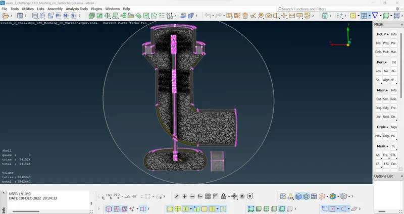
Cross-sectional view of the Turbocharger with different mesh cell sizes for each component