Week 3 Challenge : CFD meshing on Turbocharger
Aim
To create Volumetric mesh on the given model of a torbo charger.
Objective
The given model have a few geometric error, so diagonose the error and fix the model. Define the volume and assign the right PID's thendo the 2D/ shell mesh according to the given target lengths and then do the 3D mesh.
Steps
1. Fix the geometry
2. Assign PID's and create shell elements
3. Define the volume and create tetra mesh
Fix the geometry
In order to fix the first do a deometry check and find all the errors and single and triple coons and all the intersecting parts.
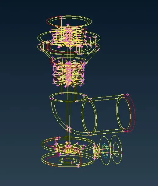
If there are intersecting surfaces like the one shon below first trim the faces using intersection tool and delete the unwanted faces
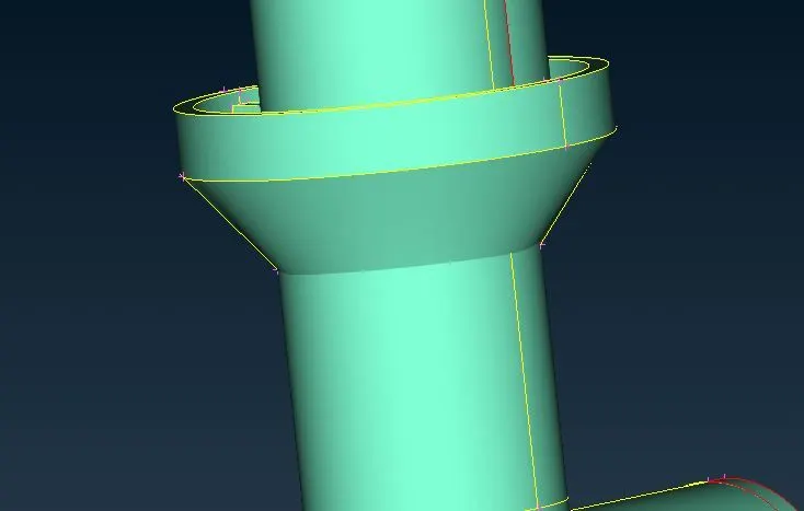
To get a straight line on the intersected part as shown below use the cut tool and delete the small face and use fill hole option.
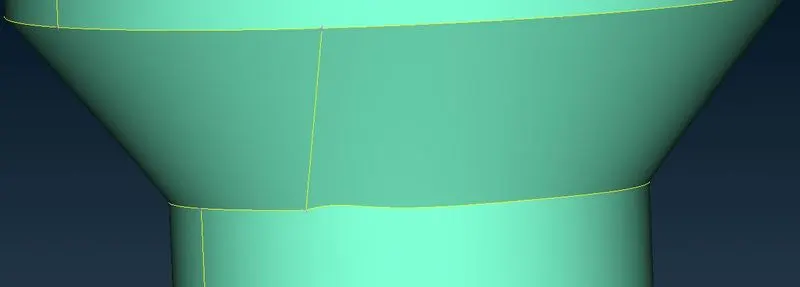
Surfaces like the one shown below where the geometry is complex we have to fix the surface using more than one operation.
I have used the COON option with selecting the yhree lines and choosing the alternate surface option will give a csmooth fave.
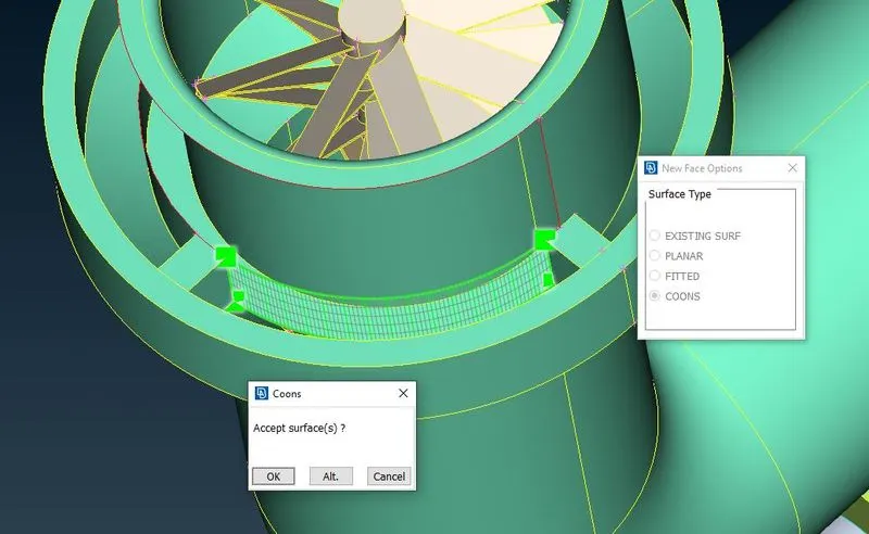
Another option is to project the bottom line to the top and then using the COON optin and four lines to create the required surface as shown below
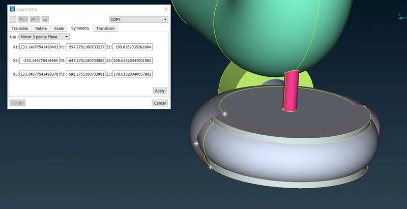
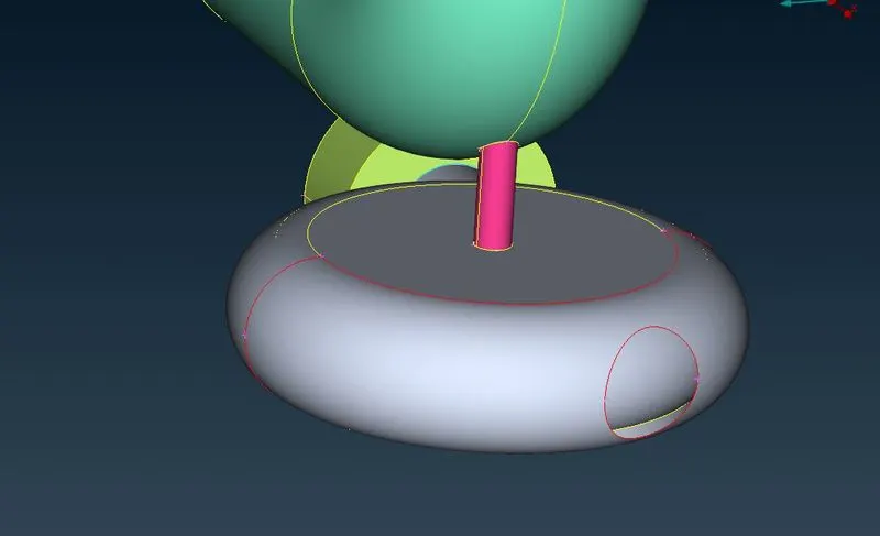
In the turbine casing where half face is missing we use the transform option to reflect the face from opposite side and using the fill hole option to fix the surface.
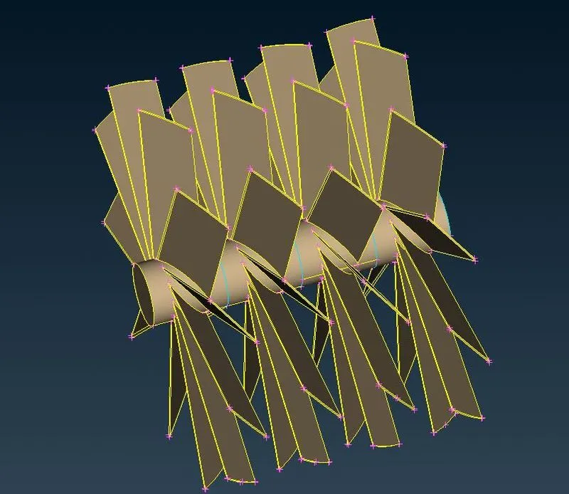
To fix the blade, impeller and shaft first we do a topo to merge all overlapping surfaces and then delete all unnecesssary faces with triple cons
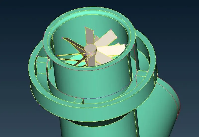
As we are doing volumetric mesh, we need to make sure there are no overlapping faces especially where the shaft and the compressor and turbine casing meet. To fix those areas project line to the shaft body and delete the overlapping face from shaft PID.
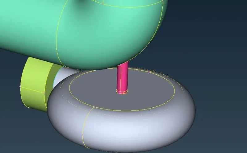
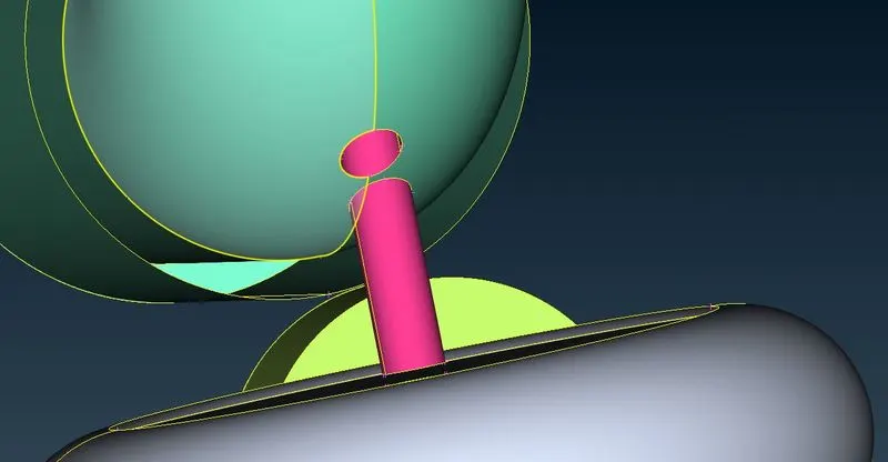
Now remove the small wedge shape body and do a geometry check to ensure all the necessary clean ups were done.
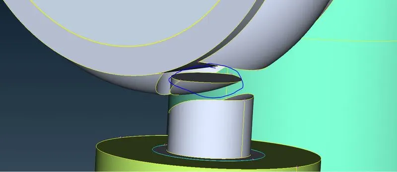
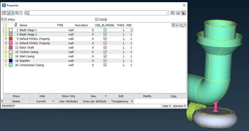
Now assign the right PID as per the given details and make sure to delete all empty PID's.
Now fill all the hole to capture the volume for volumetric meshing.
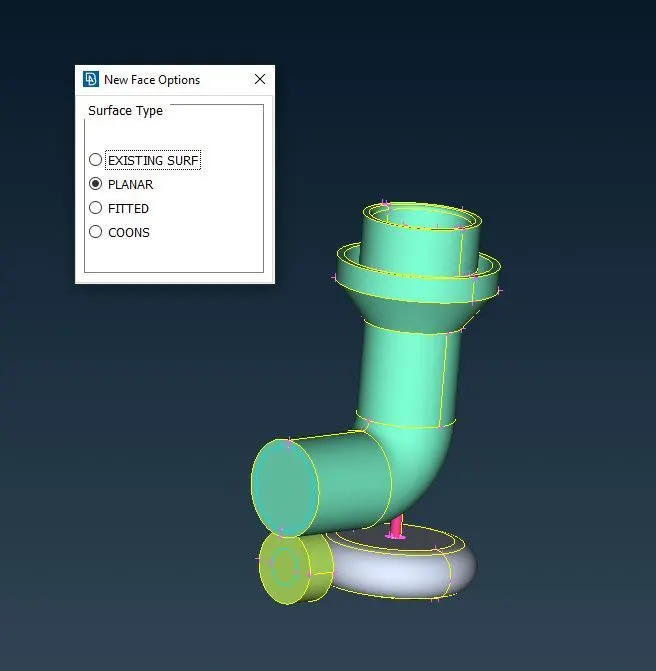
2D Mesh
Now as per the given target length create shell elements. We need to create the mesh as per the following details:
- Blade stage-1 = 1 mm
- Blade stage-2 = 1 mm
- Impeller = 2 mm
- Shaft rotor = 1 mm
- Turbo casing = 5 mm
- Compressor casing = 5 mm
- Inlet casing cover = 5 mm
We Start with 1mm target length mesh with 0.1mm as min and 2mm as max target lengths. After finishing the operation we use the freeze option to avoid the elements getting deleted where the boundaries are shared between two different target lenghts.
Similarly we do for 2mm and 5mm mesh
For 2mm mesh 1mm and 3mm were the min and max target legths respectively.
For 5mm mesh 4mm and 6mm were the min and max target legths respectively.
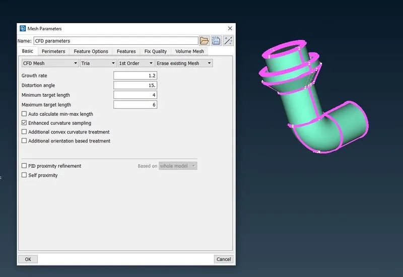
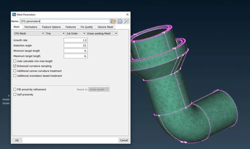
After finishing 2d meshing the model looks as per the image below with the freeze option.
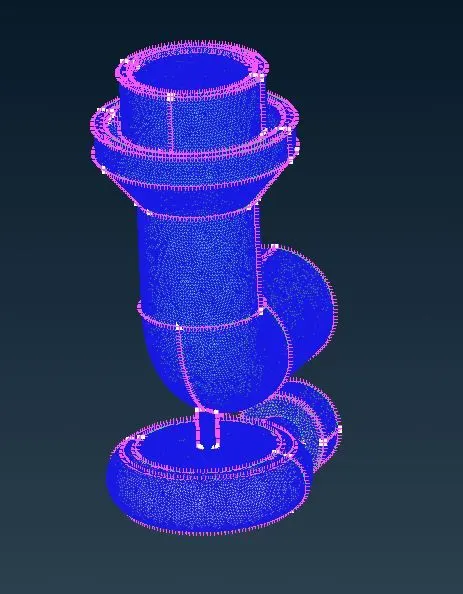
After finishing the whole 2d meshing we ufreeze the model.
Volumetric Meshing
In order to create the volumetric mesh click the define option in the Vol mesh deck and run the diagonostics.
Now keep only the internal faces and delete all external faces as we are intrested onlt in the face were the fluid flow happens.
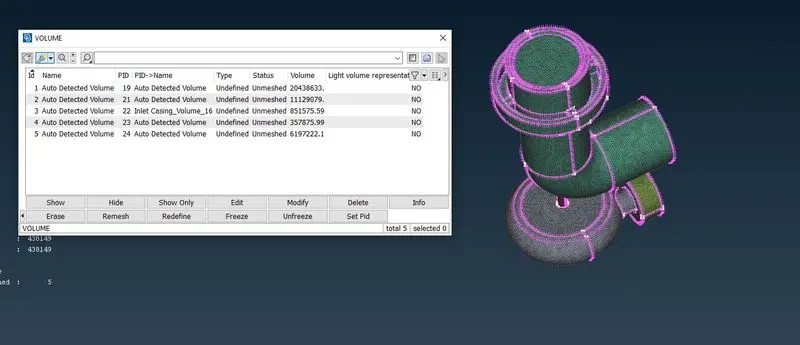
Now change the mesh type from undrfined to Tetrs CFD and remesh. to remesh right click on the window and choose remesh option.
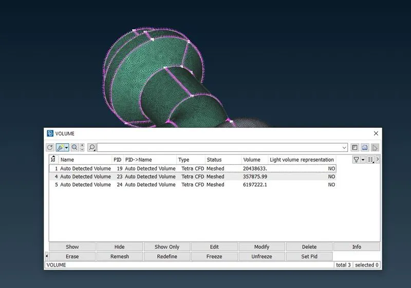
With this operation we have our volumetric mesh and we can use the cut plane option to see how the mesh looks and whether we have captured all the surfaces or if there any missing.
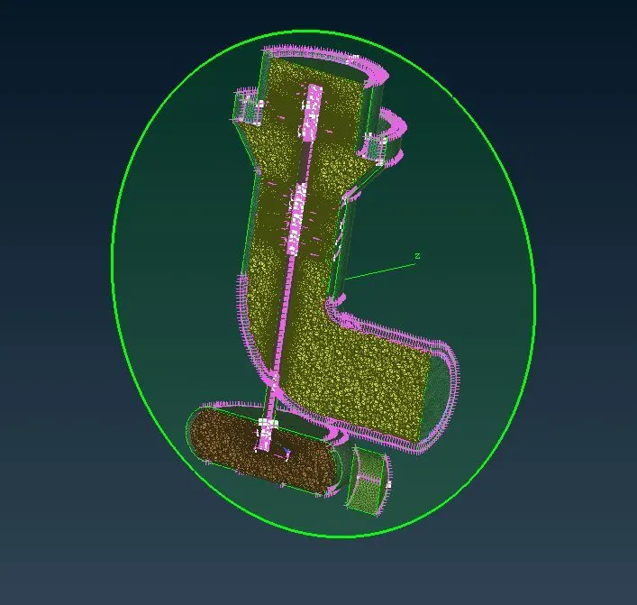
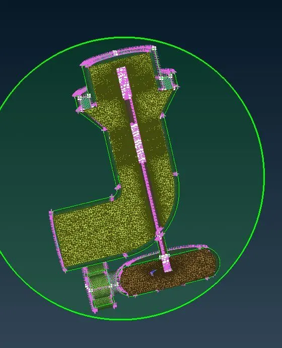
Conclusion
As per the requirement we have successfully created with volumetric mesh. And learned differnt tools from geometry, Mesh and Vol Mesh deck.
NB.
I am unable to upload the ansa file and once I tried my whole report wasgone and I have to start from the scratch.
Can you please suggest me any other alternative options.
As I got only half an hour more for submission. I will be submitting without the ANSA file.
Thank you