Project 1 : CFD Meshing for Tesla Cyber Truck
Aim
To create 2D tria mesh on a Tesla cyber truck for a wind tunnel analysis.
Objective
To Create a single volume Tesla cyber truck model in order to create a CFD mesh between the wind tunnel and the car outer surface.
Steps
The steps to complete the above mentioned task are as follows:
Step 1: Fix the geometry to clear all errors.
Step 2: Assign PID's and create shell (tria)elements for Car
Step 3. Define the volume and create shell element (tria) for wind tunnel
Fix the car geometry
As the car geometry is almost we will modify the LHS and reflect it to RHS side.
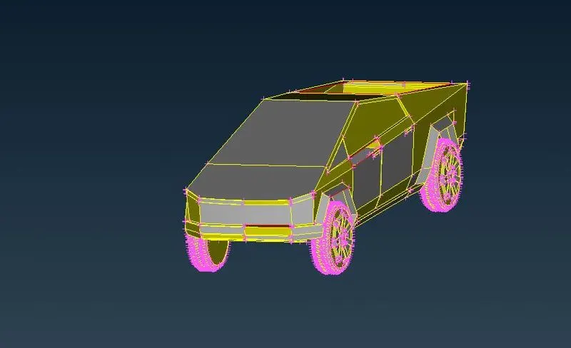
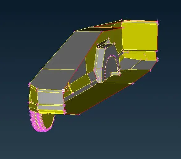
As a first step to delete the geometry in RHS side, trim the surface using the plane cut option and divide the car model into 2 halfs through the center as shown below.
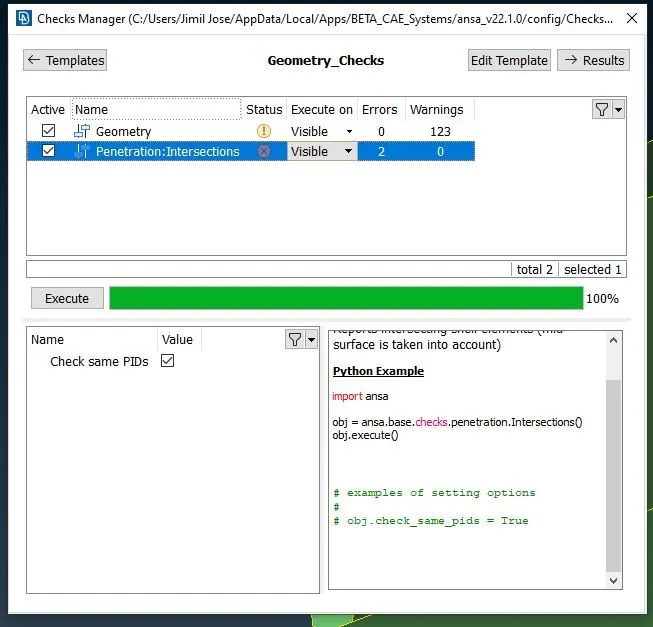
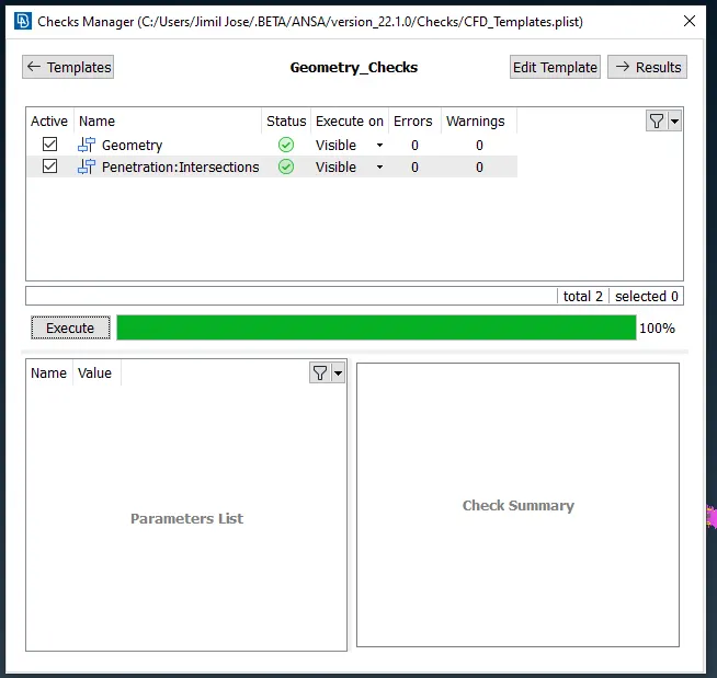
Now do a geometry check to get an idea on the surfaces which needs to be fixed. Use the check manager and select geometry option.
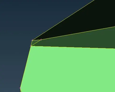
Fix all the single CONS except the one in the middle which was created by deleting the RHS side.
Fix all the geometry errors.
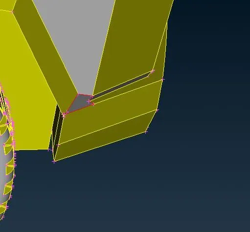
Fill the places where there are no surfaces and fix the geometries.
After fixing the geometry use ther checks manageer to confirm there are no existing geometry errors.
Assign PID's and create shell (tria)elements for Car
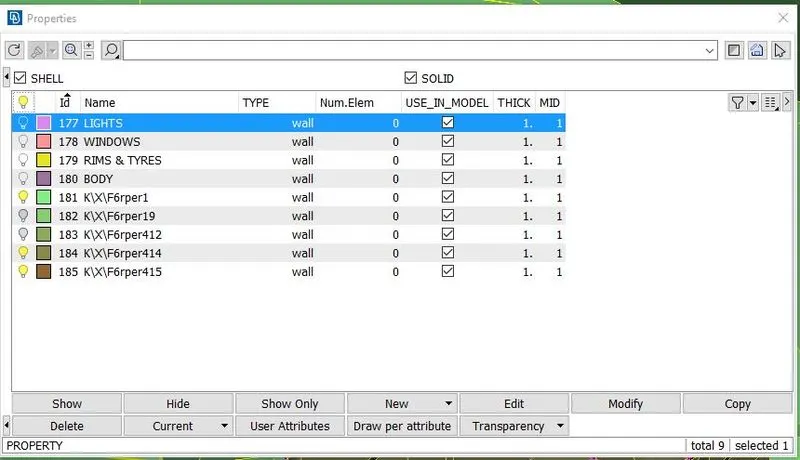
Now create different PID's and assign the surfaces accordingly. In this model we have created PID's naming LIGHTS, WINDOWS, RIMS & TYRES, BODY as shown in the figure below. Now assign the faces accordingly ang delete the unused PID's using the compress option.
Now we will start creating the mesh-tria elements.
The mesh sixes used in this model are as follows:
Tyre and Window: 2mm
Body and Lights: 3mm
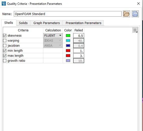
Now we will on the quality parameters as shown in the below picture:
Create shell mesh and clear all the off elements in the geometry, if any.
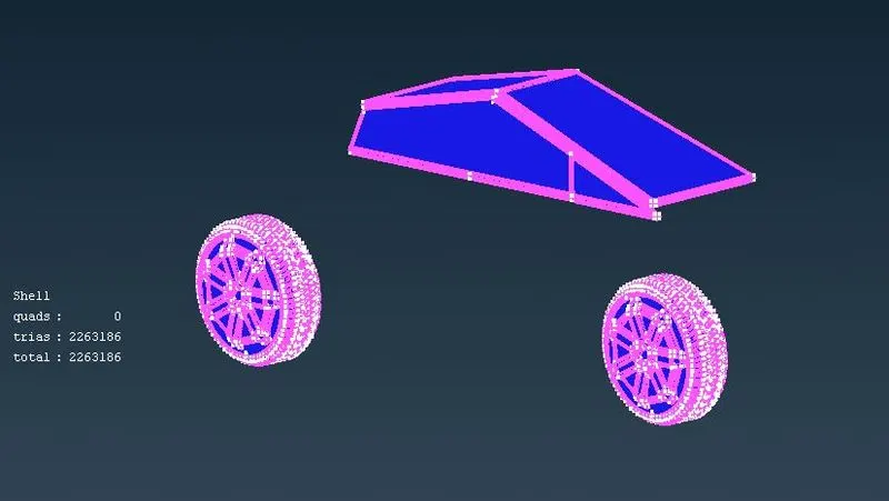
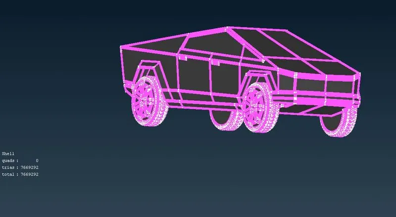
Use freeze option to freeze the created elements and then create mesh for body and the lights.
For them we use 3mm mesh size.
Now clear all off elements and unfreeze the model.
Now we will create the wind tunnel with the boundaries at 4 times the length of truck to the front and 6 times to the length at the back as shown below.
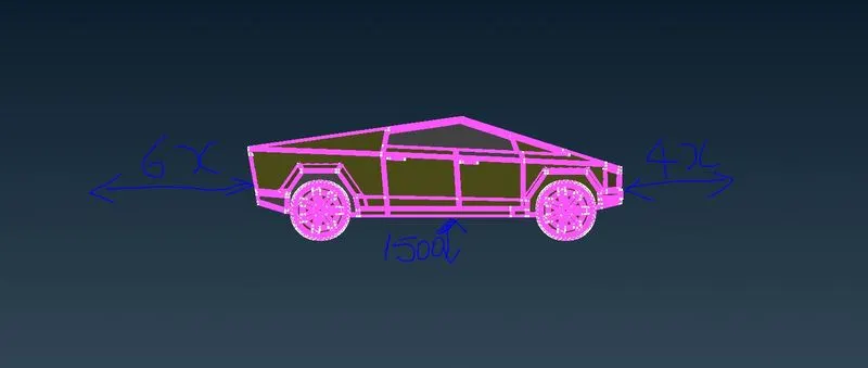
The bottom boundary will be created at a distance of 1500mm.
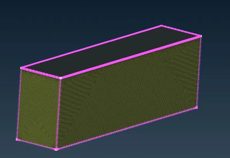
The finished wind tunnel will be looking as follows:
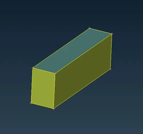
Now we will set the spacinge manually with a mesh growth rate of 1.2 starting from the bottom face and create mesh.
The mesh generation is shown below.
Conclusion
Now we have successfully created the 2D elemnts on the given model and we have created a windtunnel model and mesh for CFD analysis.
Note: As the size of the file is more than 700 MB, I am unable to upload the original file.
Let me know if I have to upload the file.