Week 3 Challenge : CFD meshing on Turbocharger
Aim:
For the given Turbocharger model, check the geometrical errors to make appropriate volumes. Create and assign PID’s, surface mesh with the given target length as per PID’s.
- Blade stage-1: 1mm
- Blade Stage-2: 1mm
- Impeller: 2mm
- Shaft rotor: 1mm
- Turbo casing: 5mm
- Compressor casing: 5mm
- Inlet casing cover: 5mm
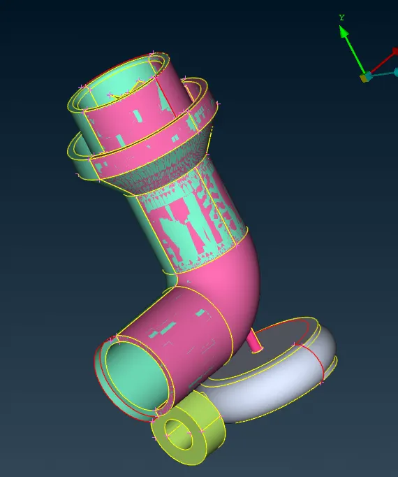
Procedure:
- Open ANSA, change to CFD mode then click on the “?” symbol another window is opened in which scroll down you will find “-performance_mode 3” copy and paste it near the “?” symbol click ok.
- Drag and drop the Turbocharger model in the ANSA window.
- Click on Tools >> Checks >> Geometry >> Execute. Now we could see the error which we need to clean up in topology in order to resolve the error.
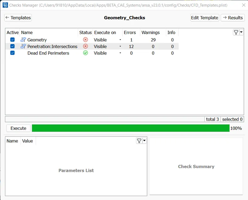
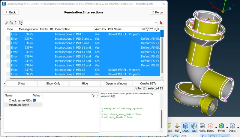
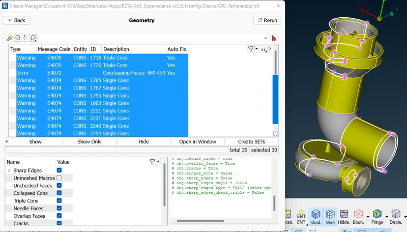
- It is necessary to resolve both the geometric and intersection errors.
- From the Model it is seen that there is overlap face which is shown as glitch, so using PID remove the green Coloured PID, then delete the overlap surface using, TOPO >> Face >> Delete >> Select the Surface >> Middle click Mouse >> Ok.
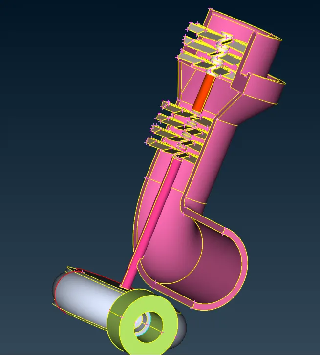
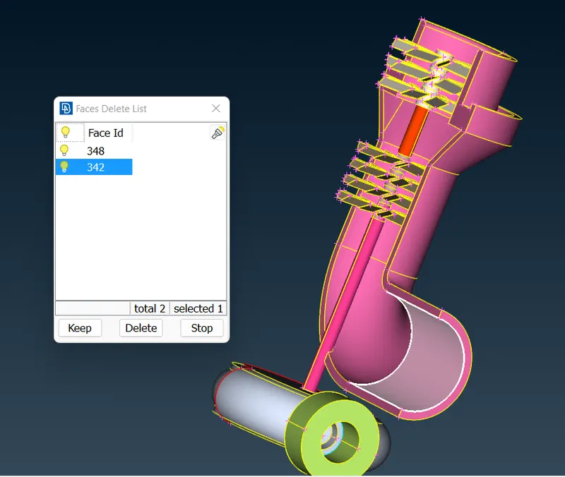
- Delete the extended surface, TOPO >> Face >> Delete >> Select the Surface >> Middle click Mouse >> Ok. Create new surface, TOPO >> Face >> Loop >> Select the single Cons >> Middle Click Mouse >> Ok.
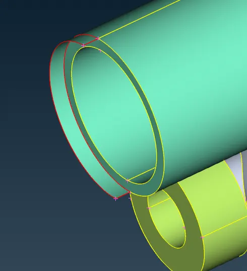
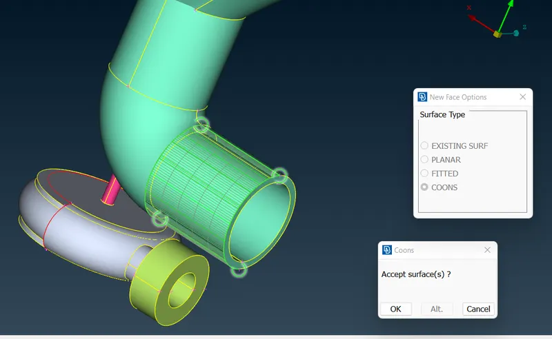
- Face is missing in the geometry which cannot be directly created by selecting new face as it has various hot spots at different height.
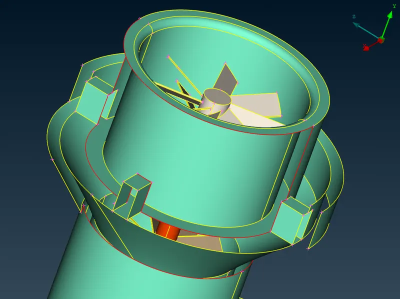
- So, we will project the curve so that two hot spots are aligned in a single line such that they form a box. TOPO >> Curves >> Transform >> Select the desired curve to project >> Middle click Mouse >> Select the nodes >> Ok. Now, Select the TOPO >> Face >> Loop >> Select the single Cons >> Middle Click Mouse >> Ok.
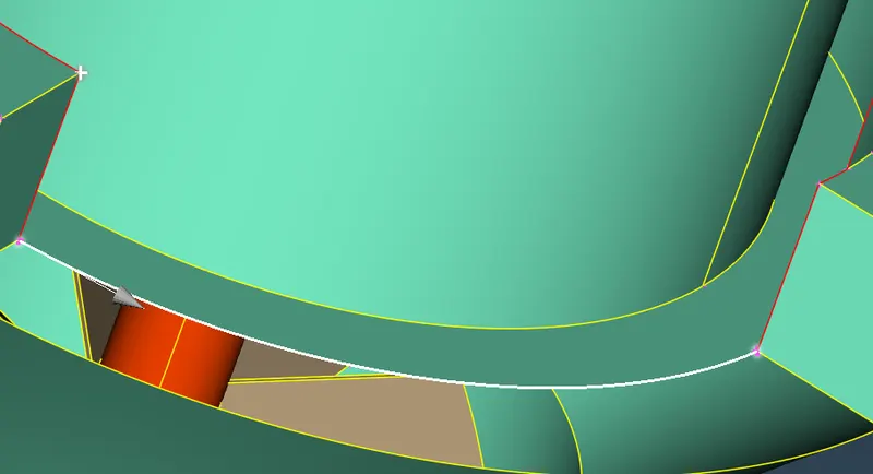
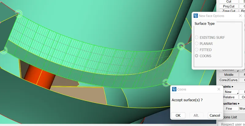
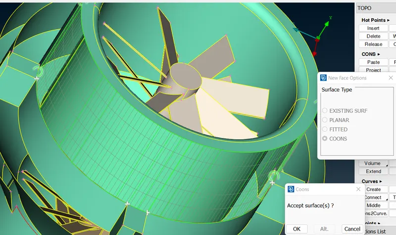
- Delete the Projected curve.
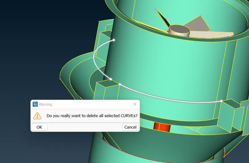
- From the model it is seen that there is no single cons visible, when checked it intersect with two surface. So we will delete both the surface.
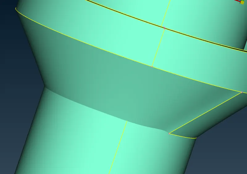
- Project the Hot spot from top face to the bottom face now transfer the bottom curve to the top face and create a face. Delete the unwanted Hot spot.
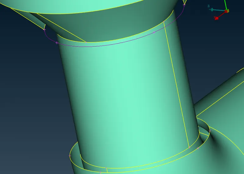
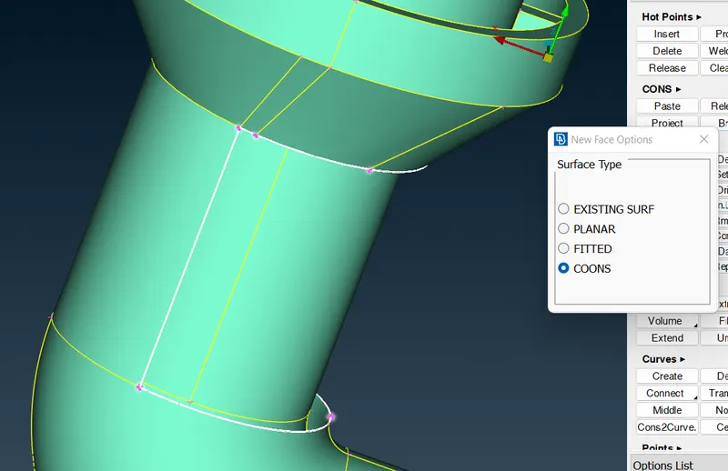
- Project two Hot spot from the bottom face to the top face and create the face using Cons option. Now for the remaining surface, Select the TOPO >> Face >> Loop >> Select the single Cons >> Middle Click Mouse >> Ok.
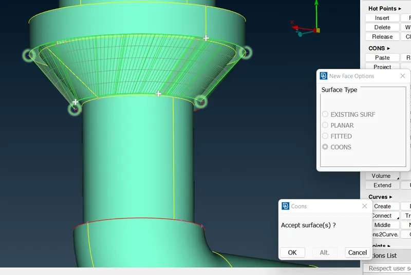
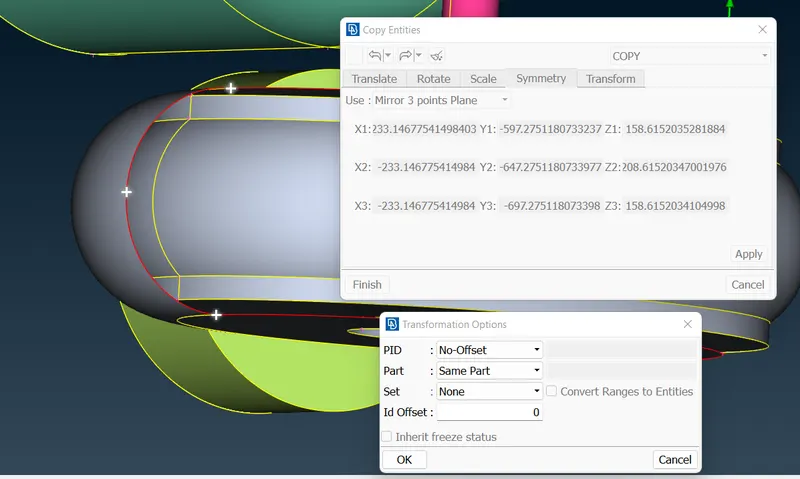
- Curve missing from the model, Insert Hot spot in the curve. Now, using Transform >> Copy >> Select the Curved Surface >> Symmetry >> Mirror 3-point plane >> Ok >> Finish.
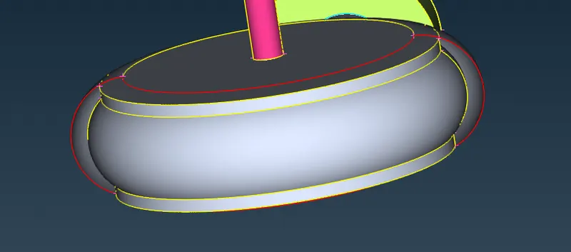
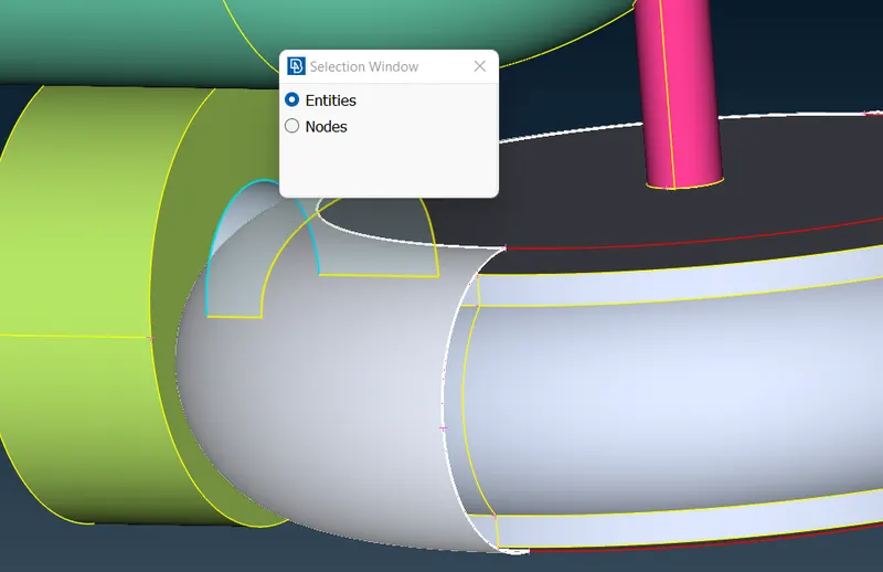
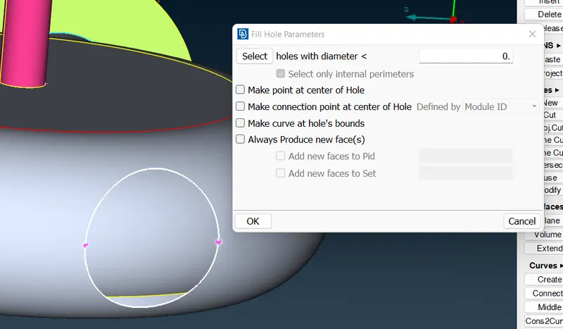
- Hole is formed in the created surface this is due to the hole on the other side. TOPO >> Cons >> Fill Hole Select the Cons >> Ok. Select the TOPO to fix the surface Single Cons.
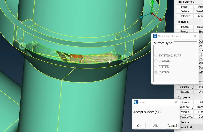
- Create new surface at the gap of the model, which is essential for the volume mesh. As a result of new surface Triple cons are formed which is essential.
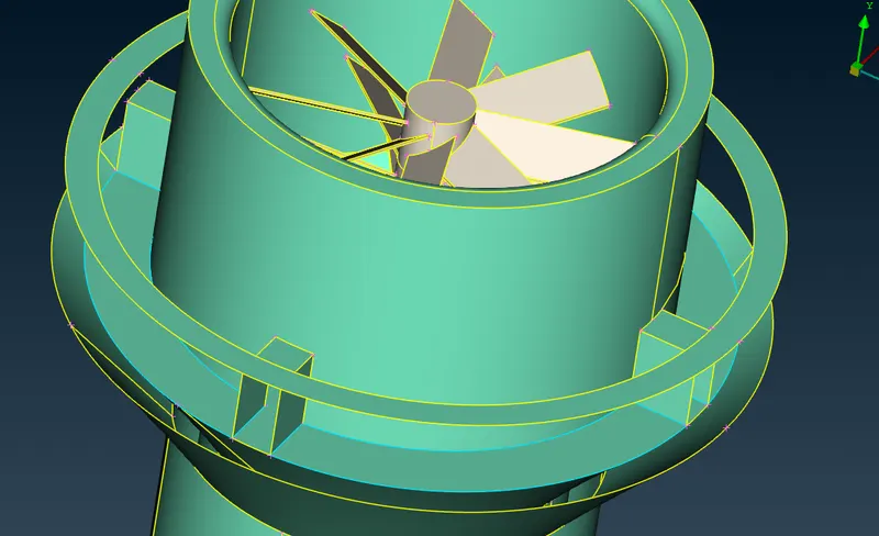
- Now, let’s start resolving the Intersection errors.
- If a Component consist of many intersecting surfaces which divide the body, then ANSA will not consider it as single volume but multi volume body so it is necessary to remove these intersecting surfaces from the model before volume meshing.
- In order to do so we will simply delete these surfaces. From the model it is seen that blade stage-1 consist of triple cons, when you isolate to view the surface, you will find the intersecting surfaces. TOPO >> Face >> Delete >> Select the surface >> Ok. Repeat the procedure until you have eliminated the intersecting surfaces.
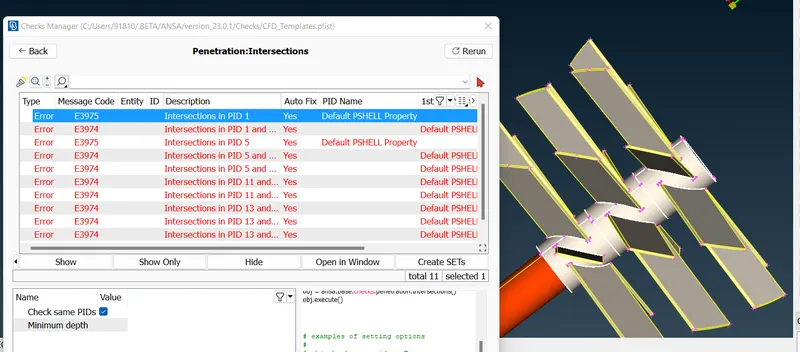
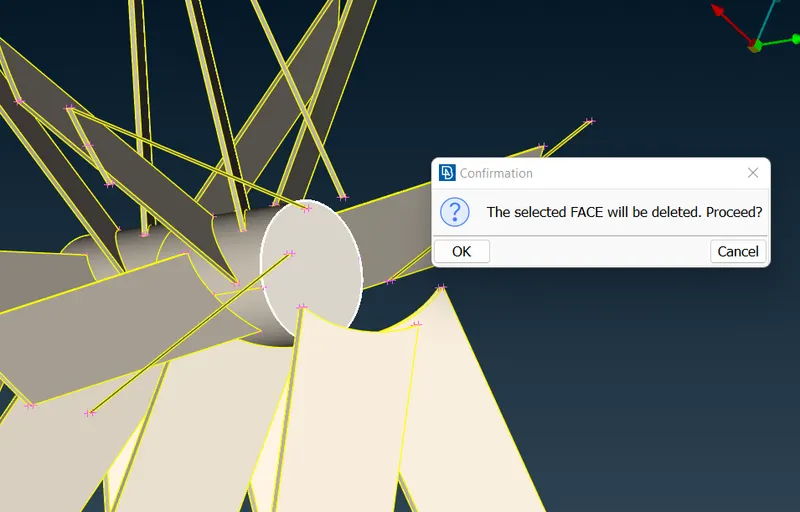
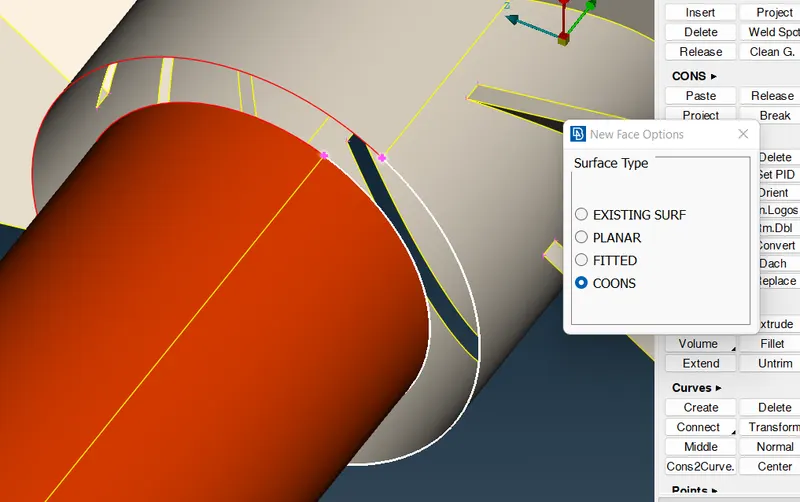
- There is glitch at the intersection of the shaft and blade stage-1, so delete both the shaft and blade surface then create new surface using cons without assigning any PID as we will assign in the later stage.
- Similarly, follow the above steps for blade stage-2 to eliminate intersection surface. Now at the end of stage-2 you will find glitch, these is due to the overlap between the blade and shaft surfaces. So, in order to resolve we will project the cons on to the shaft surface and delete the overlap surface.
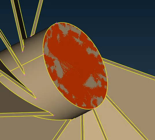
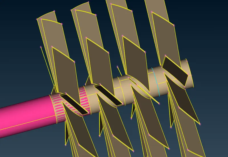
- TOPO >> Cons >> Project >> Select the cons at the end of the stage-2 >> Middle click mouse >> Select the shaft Surfaces >> Middle click mouse. Now, hide the stage-2 you will find the cons on the surface of the shaft simply delete the surface.
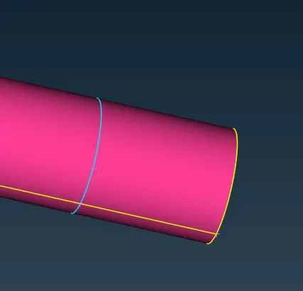
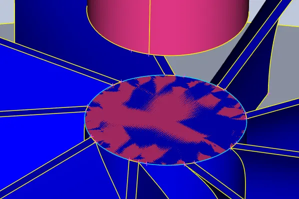
- Now, at the intersection of the shaft and the compressor casing there is intersection. When isolating the section, we could see that there is glitch due to overlap and the shaft has entered into the thickness of the casing. So will delete the glitch surface such that only the shaft surface is visible.
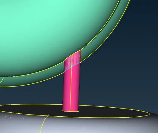
- TOPO >> Cons >> Project >> Select the cons at one end of the casing >> Middle click mouse >> Select the shaft Surfaces >> Middle click mouse. Similarly, follow the steps for the other end of the casing and then delete the shaft surface which is present at the thickness of the casing.
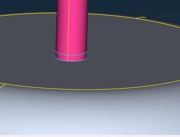
- We have discontinued shaft, since this is internal flow analysis however, we are going to eliminate these surfaces at the volume mesh so no need to worry about.
- Follow the above steps at the intersection of the shaft and turbine casing.
- Close all the opening of the model using TOPO >> Face >> New >> Planar >> Select the desired Single Cons >> Middle click mouse >> Ok. Repeat the procedure at the all opening.
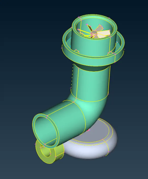
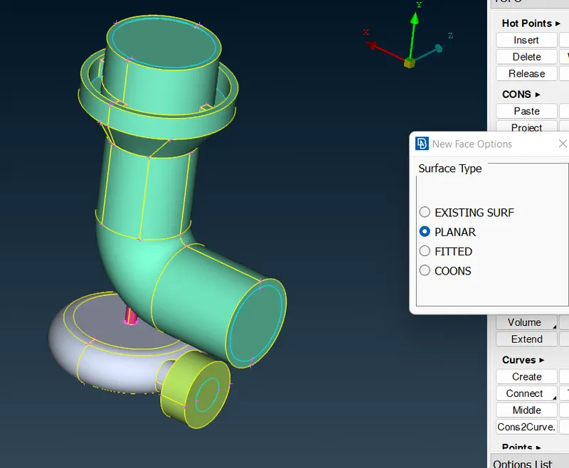
- Check the geometry check again for the model, all the intersection errors are resolved only triple cons in the geometric errors are visible which is unavoidable.
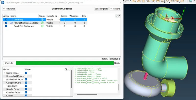
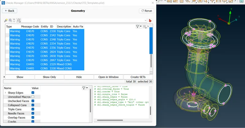
- Let’s start creating the PID’s for the model. Open the PID table Hiding all the component except one and double click on the PID and rename the component. Repeat this procedure to all the component.
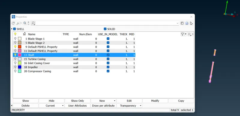
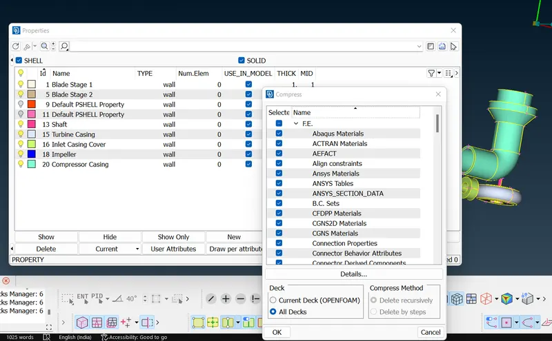
- When checked the shaft consist of two PID’s so select one PID >> Right click >> Apply >> Select the entire shaft >> Middle click mouse.
- In order to delete unwanted PID Click Compress >> Ok.
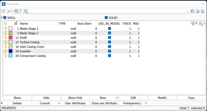
- Let’s start component wise surface mesh. We will start with the minimum element size and then proceed to maximum.
1mm Mesh: Blade stage-1 & 2, Shaft
- From the PID table hide all the other component.
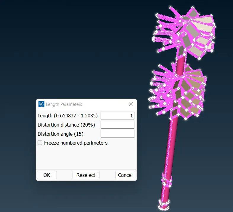
- Mesh >> Perimeter >> Spacing >> Auto CFD >> Perimeter >> Select the desired component >> Provide the Max. & Min. range for the element length >> Middle click mouse.
- Macros >> Select the desired component >> Provide the Max. & Min. range for the element length >> Middle click mouse >> OK. This Condition is provided to ANSA so that during mesh generation it is limited to the provided range.
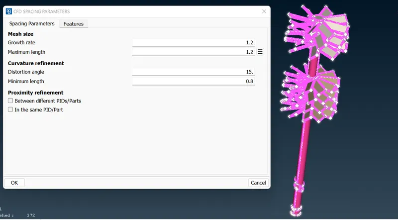
- Mesh >> Length >> Perimeter >> 1mm >> Ok >> Macros >> 1mm >> Ok.
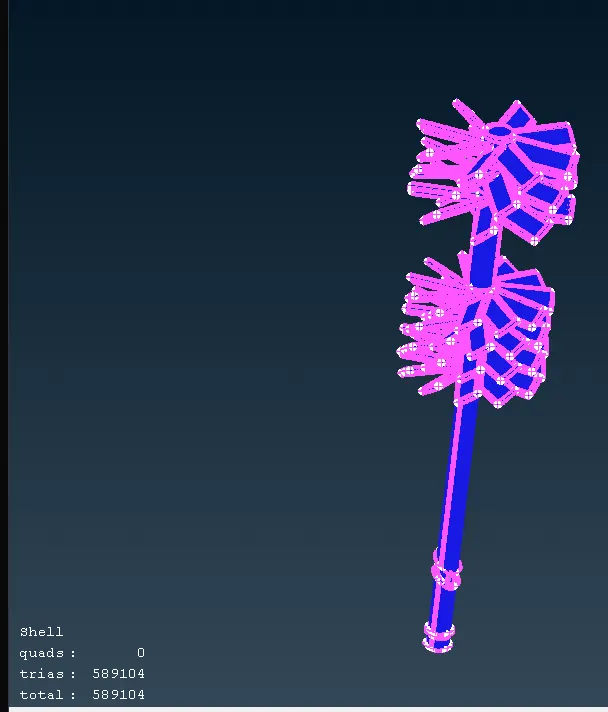
- Mesh Generation >> Choose Tria element.
- Mesh Generation >> CFD >> Visible. Mesh is created.
- Now, Freeze the entire component, without doing so mesh generation will not happen at any of the component due to varying mesh size at the intersection. Hence, we will freeze the mesh component at the end of mesh generation.
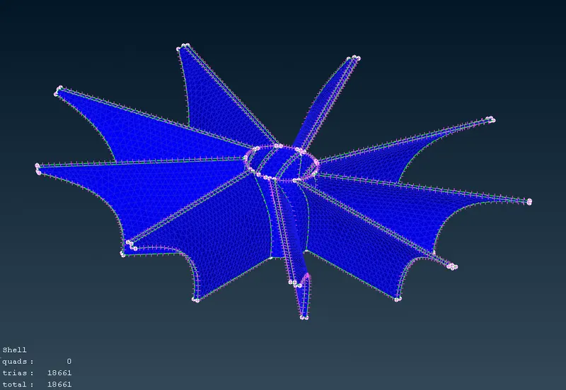
2mm Mesh: Impeller
- From the PID table hide all the other component.
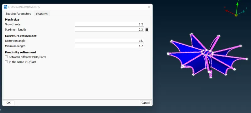
- Mesh >> Perimeter >> Spacing >> Auto CFD >> Perimeter >> Select the desired component >> Provide the Max. & Min. range for the element length >> Middle click mouse.
- Macros >> Select the desired component >> Provide the Max. & Min. range for the element length >> Middle click mouse >> OK. This Condition is provided to ANSA so that during mesh generation it is limited to the provided range.
- Mesh >> Length >> Perimeter >> 1mm >> Ok >> Macros >> 1mm >> Ok.
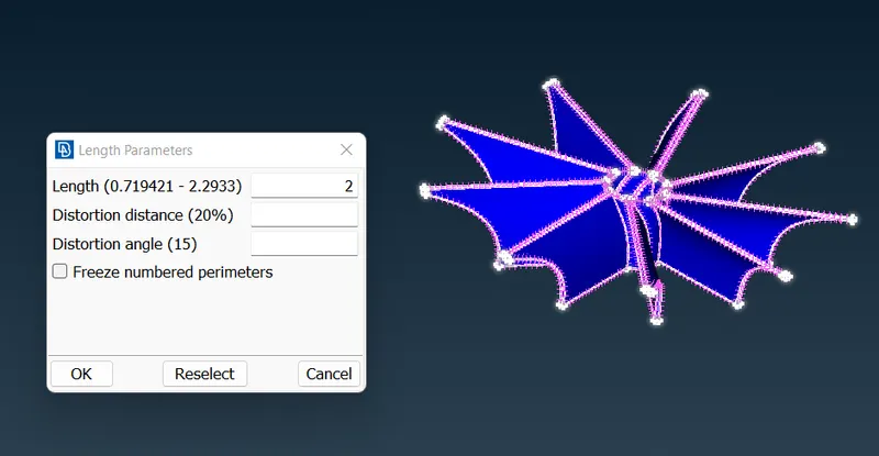
- Mesh Generation >> Choose Tria element.
- Mesh Generation >> CFD >> Visible. Mesh is created.
- Now, Freeze the entire component, without doing so mesh generation will not happen at any of the component due to varying mesh size at the intersection. Hence, we will freeze the mesh component at the end of mesh generation.
5mm Mesh: Compressor casing, Turbine casing & Inlet casing cover
- From the PID table hide all the other component.
- Mesh >> Perimeter >> Spacing >> Auto CFD >> Perimeter >> Select the desired component >> Provide the Max. & Min. range for the element length >> Middle click mouse.
- Macros >> Select the desired component >> Provide the Max. & Min. range for the element length >> Middle click mouse >> OK. This Condition is provided to ANSA so that during mesh generation it is limited to the provided range.
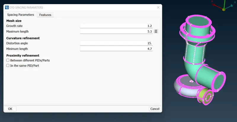
- Mesh >> Length >> Perimeter >> 1mm >> Ok >> Macros >> 1mm >> Ok.
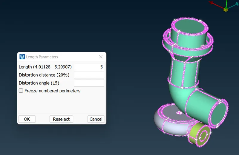
- Mesh Generation >> Choose Tria element.
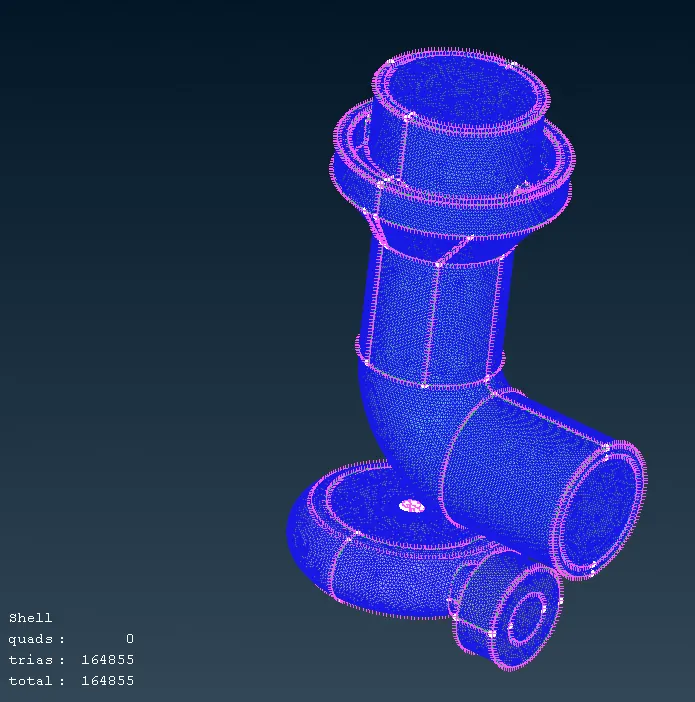
- Mesh Generation >> CFD >> Visible. Mesh is created.
- Now, Freeze the entire component, without doing so mesh generation will not happen at any of the component due to varying mesh size at the intersection. Hence, we will freeze the mesh component at the end of mesh generation.
Volume Mesh:
- Now, un freeze all the component one’s individual mesh of the component is completed.

- We will start with volume mesh.
- Volume Mesh >> Define >> Delete the Un-Wanted volume, keeping only the internal volume. Since this analysis for the model is internal so leaving the internal volume delete all the external volume.
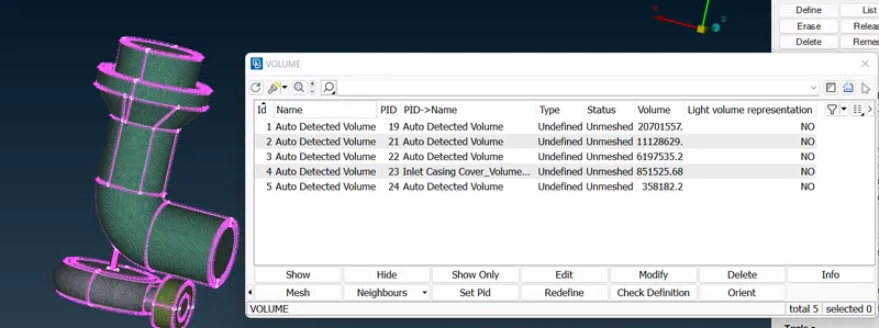
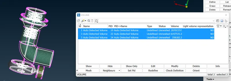
- Type of volume mesh needs to be defined so select the Unstructured Mesh >> Tetra CFD for all the Volume.
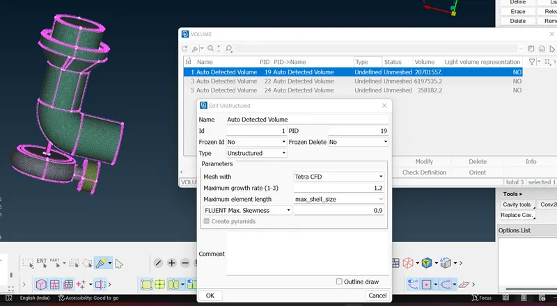
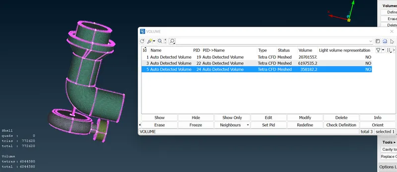
- Right click in the mesh status >> Mesh >> Ok for all the Volume.
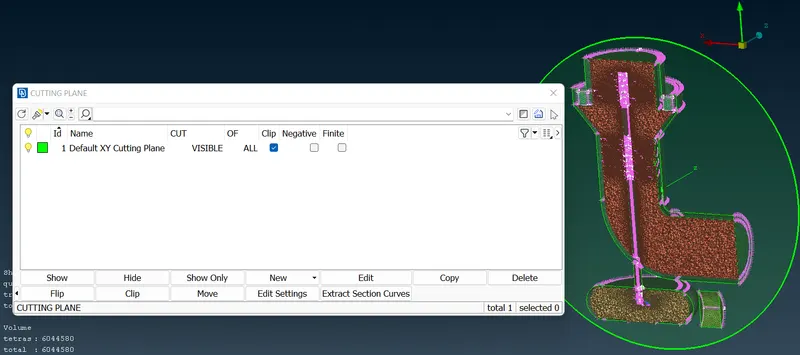
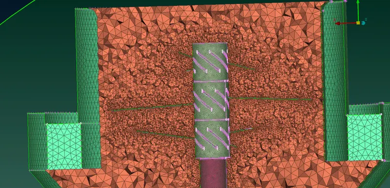
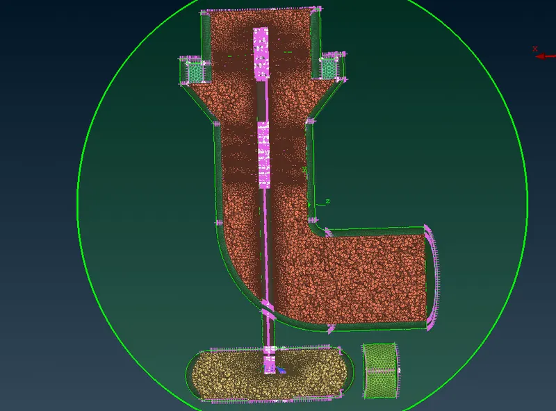
- In order to check the volume mesh, we use cut plane option. Cut Plane >> New >> Default XY (desired plane to view cut section) >> select the node as reference for the plane position >> Ok.
Result:
|
Sr. No. |
Element Size |
No. of Element |
Component |
|
1 |
1mm |
5,89,104 |
Blade stage-1 & 2, Shaft |
|
2 |
2mm |
18,661 |
Impeller |
|
3 |
5mm |
1,64,855 |
Compressor casing, Turbine casing & Inlet casing cover |
- No. of elements in Surface mesh is 7,72,620 for whole geometric model.
- No. of elements in volume mesh is 60,44,580 for whole geometric model.
Conclusion:
- Thus given Geometrical model is resolved from all the errors and Volume mesh is created for the provided Mesh element size.
Mesh File:
https://drive.google.com/file/d/1Gsb49rJngVYuMwBdIfdPpguqQrxw3HUO/view?usp=share_link