Week 3 Challenge : CFD meshing on Turbocharger
AIM:
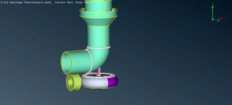
To perform topology cleanup ,create and assign PIDs then mesh the given model with different target lengths and volumetric mesh can be done for the required volume.
OBJECTIVES:
1) To do TOPO cleanup and assign PID for the different components of the turbocharger.
2) To do surface mesh for the different components of turbocharger by using the PIDS we assigned to them.
3) To do volume mesh for the given turbo charger model.
PROCEDURE:
In here we are using ANSA. ANSA is an preprocessing tool that provides all funtioality for full mode build up fromCAD data to ready to run solver input file,in a single integrated environment.
STEP - 1:Open the given model with ANSA and imeditiatly go for the geomentry checks here we can single cons , double cons,overlapped surfaces so these are the geomentrical errors firstly need to be eliminated.
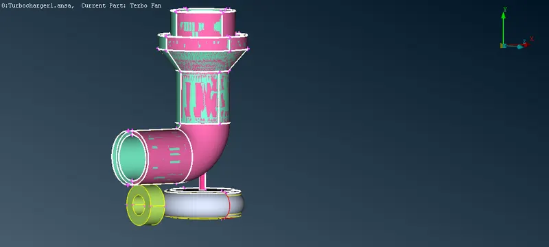
STEP - 2 :first delete the overlapped surface above the pressure valve casing. It can identified as pink glitches on over the green color. To delete that pink surface go to PID and select the color pink now to isolate this surface either right click on the PID and select show only or make sure only bulb present left to the pink color glow and turn off others by just clicking on them.
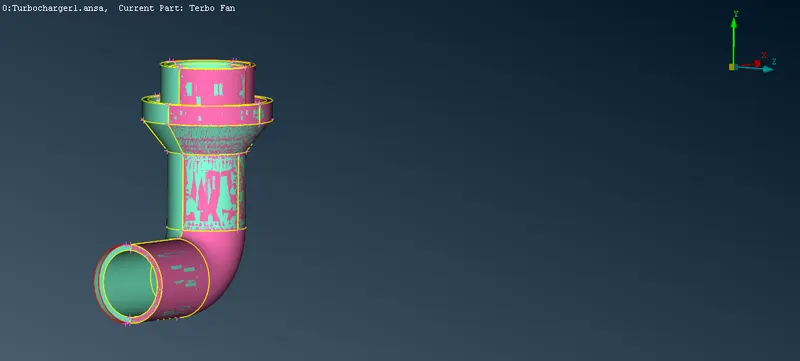
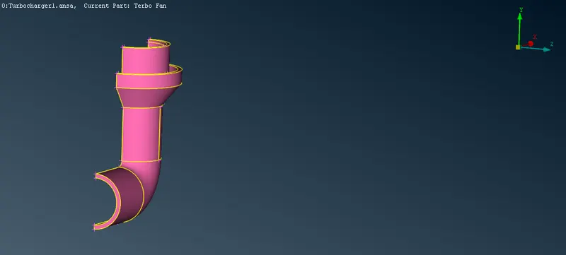
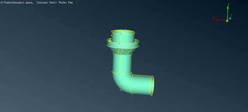
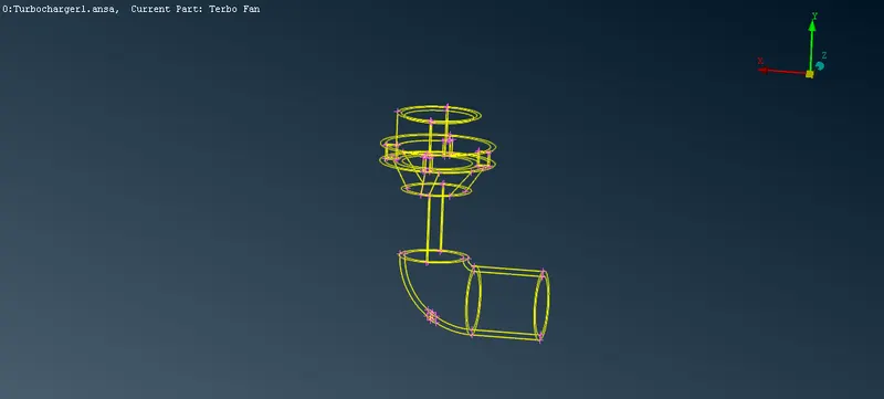
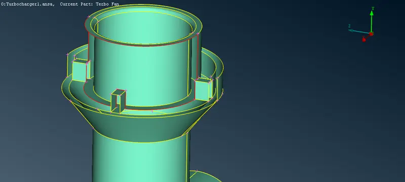
STEP - 3 :Isolate the pressure casing part and by using geomentry checks in the tools bar right arrow near volume - strips>checks>checks manager> its found there are some red cons need to be cleared.In the mid portion of the pressure casing cons connecting there is not prefectly circular in shape for that we need to intersect the two portions one is cylindercal and the other conical in shape do intersect by faces>intersectand delete unwanted surfaces .new cons are created to delete the unshaped area use hots points > projects and delete that area by faces>delete.select the faces need to be deleted.
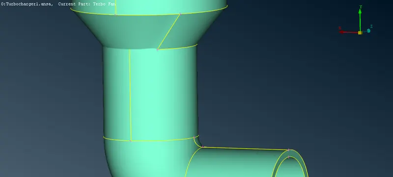
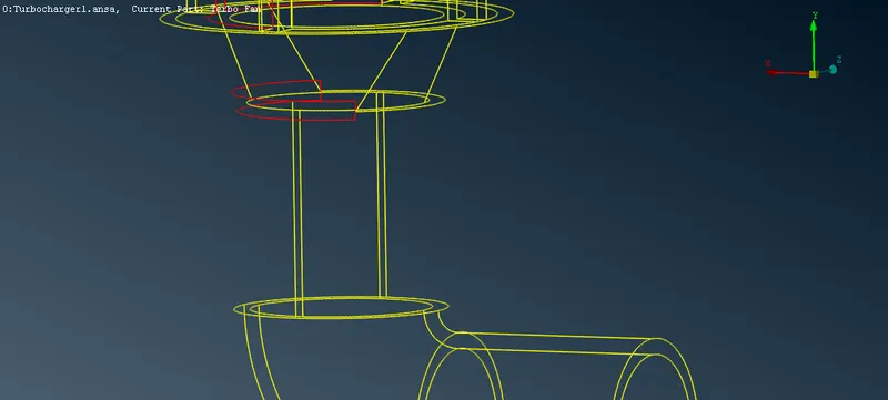
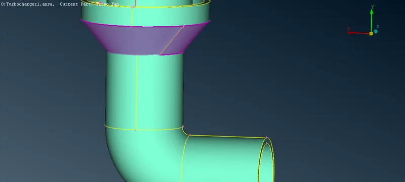
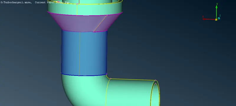
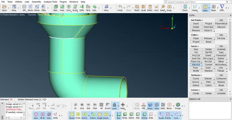
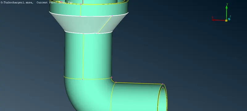
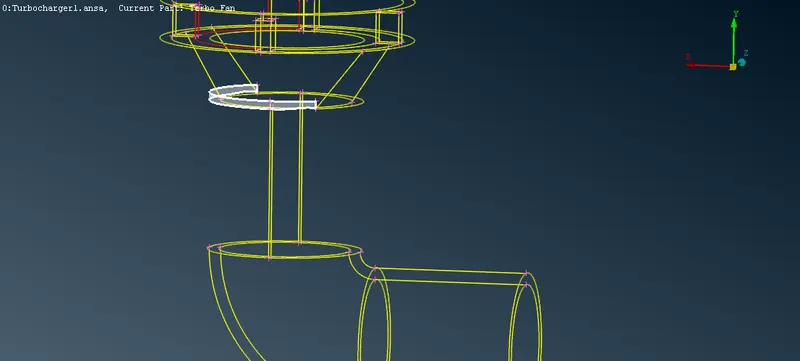
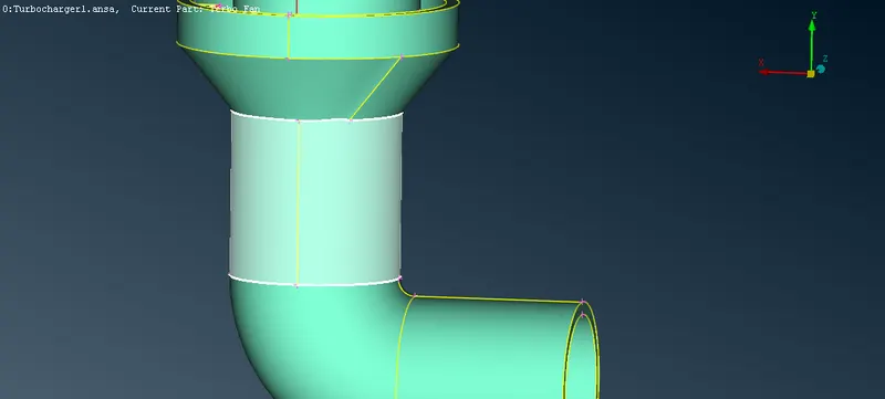
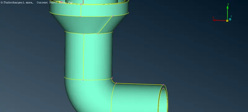
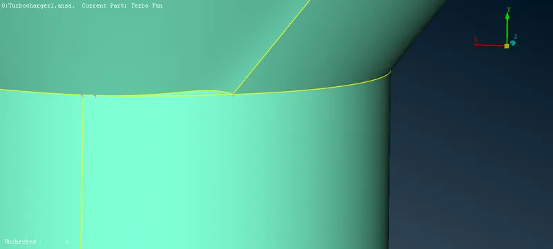
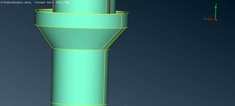
STEP - 4 :And another red con to remove that go to curves in topo deck >transform>need to form a curve copy the one curve set dircetion and two hot points which can be start and end points of the curve. After forming the curves in both sides now for the missing surface by using faces>new>coonc>loop.to make sure there are no more geomentrical errors in this section use faces>topo>select entire pressure valve
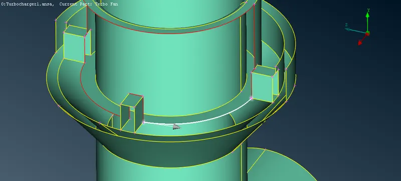
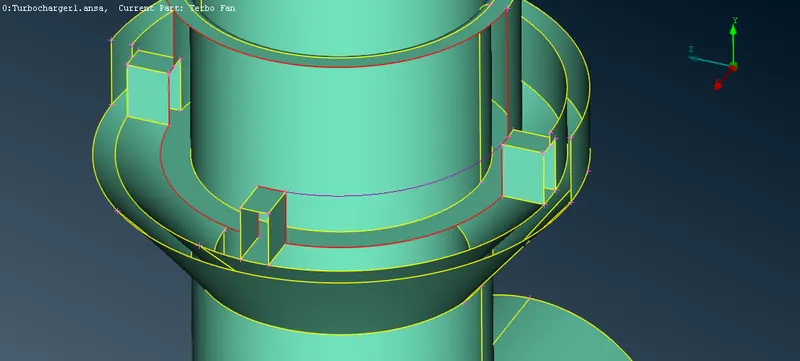
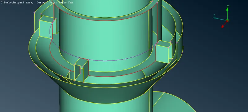
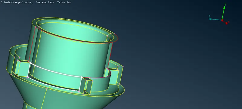
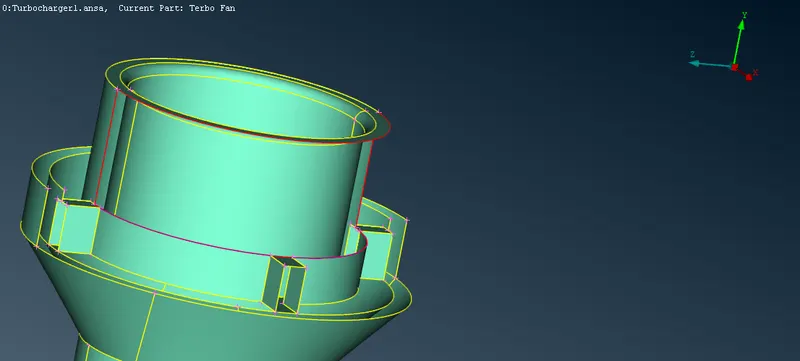
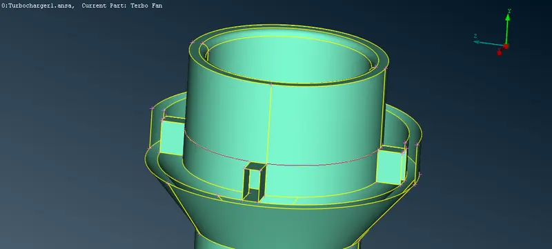
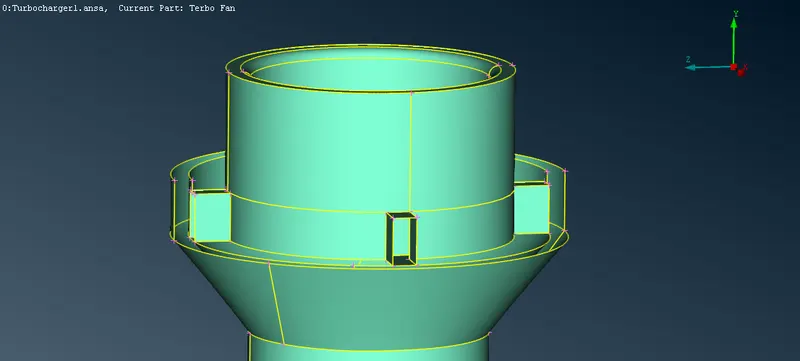
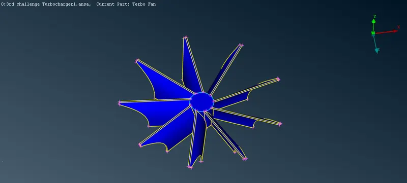
STEP - 5 :Now we can move to the next section rotory shaft with blades.Isolate the shaft and blades in it do a topo for that go to tool bar>checks>check faces>topo>select the part and do middle click.
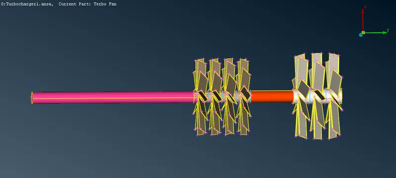
STEP - 6: In here we can see lot of triple cons and need to eliminate each and every one of them.By using NOT option in ENT mode select the parts before the triple cons ther will be surface present it will be deleted.like that all the triple cons are deleted.
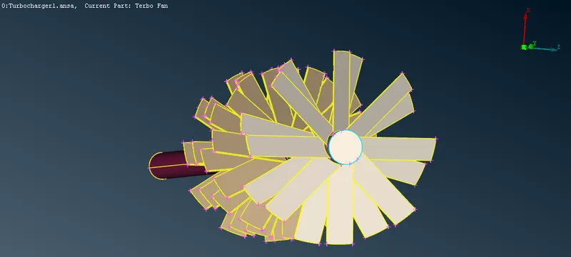
STEP - 7 :There is an overlapped surface in pink colored .we can see that shaft connected through the second stage blades.we need to project the triple cons in the pink region and isolate the shaft by using NOT on the bladesand delete the excess portion.
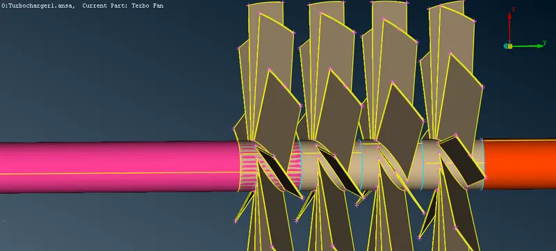
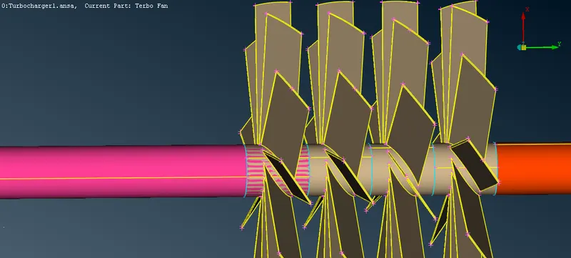
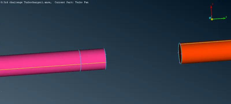
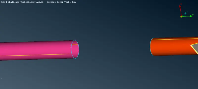
STEP - 7 : The orange colored region of the shaft need to connect the stage one blades to clear the red cons go to faces>coons>loop>select the portion need to be formed. Still can have some red cons to clear that faces>topo can be used.
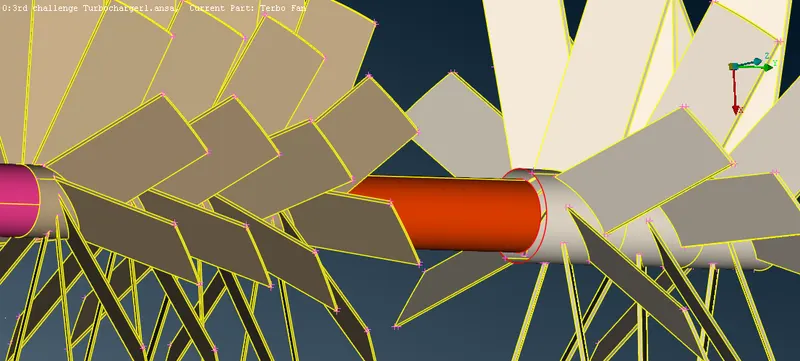
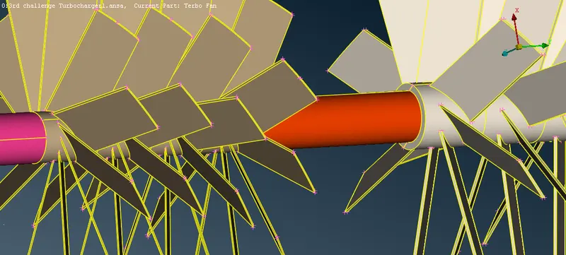
STEP - 8 : The turbo casing has a missing suface to create the surface first create a hot point exactly in the middle of the by hotpoints>new>select in topo deck. Go to the tools bar click the right arrow near snap shot >transform>copy>select an entity which is the other half do middle click>in the popuped box selcet symmentry>mirror 3 pont symmentry>select three hot points in one end do middle click. ther is a hole in the newly formed surface. Again do faces>topo.
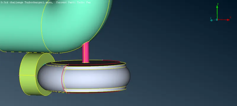
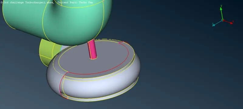
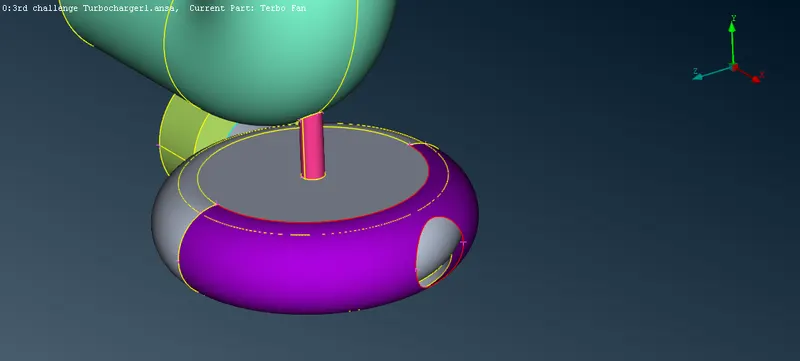
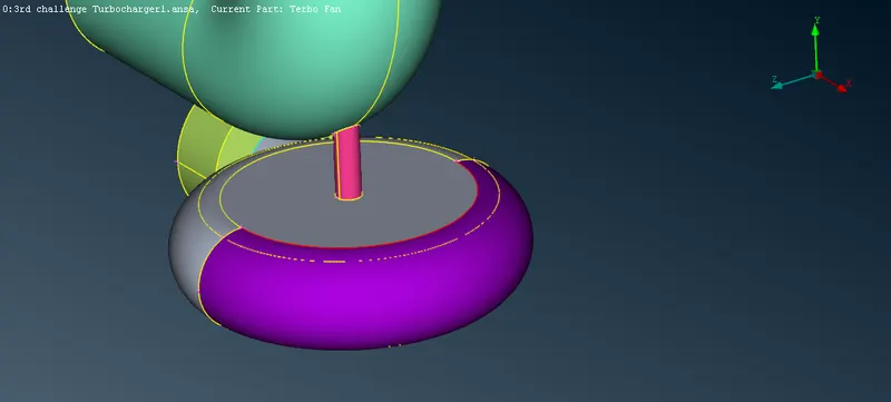
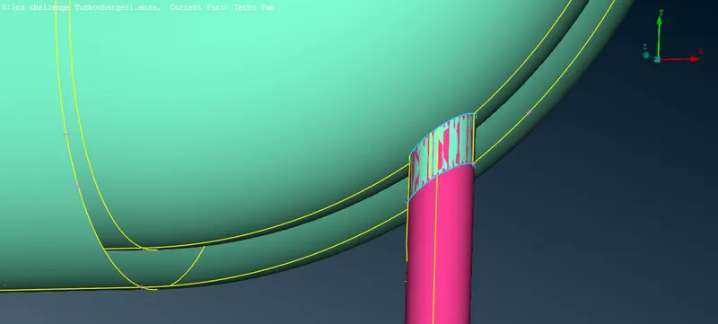
STEP - 9 : There will be an over lapped surface that has to be deleted. To delete that surface in between for that project the cons . Go to cons>project>select the cons need to be projected and do middle click. now the surface can be deleted by faces > delete.
.
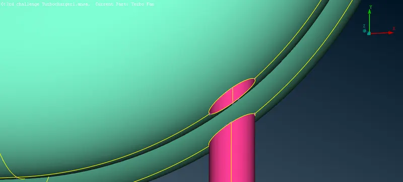
STEP - 10 : Same way there is also an overlapped surface which is in the shaft that connects the pressure casing and the turbo casing.that also eliminated by the same way of projecting the cons ,isolate the overlapped surface and delete the surface by faces>delete.
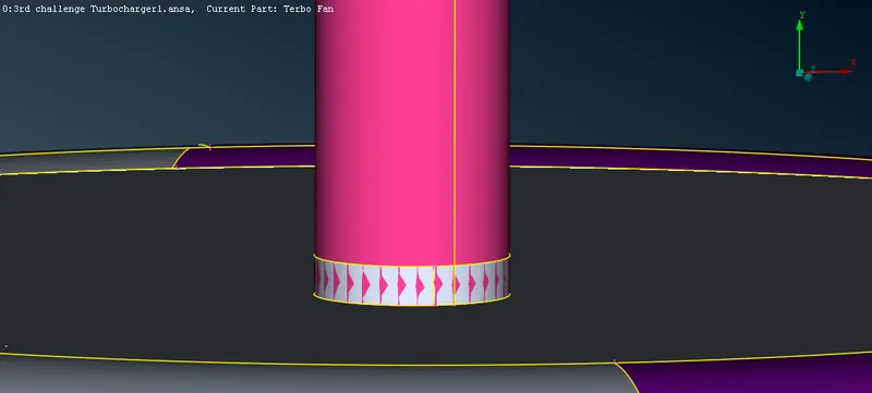
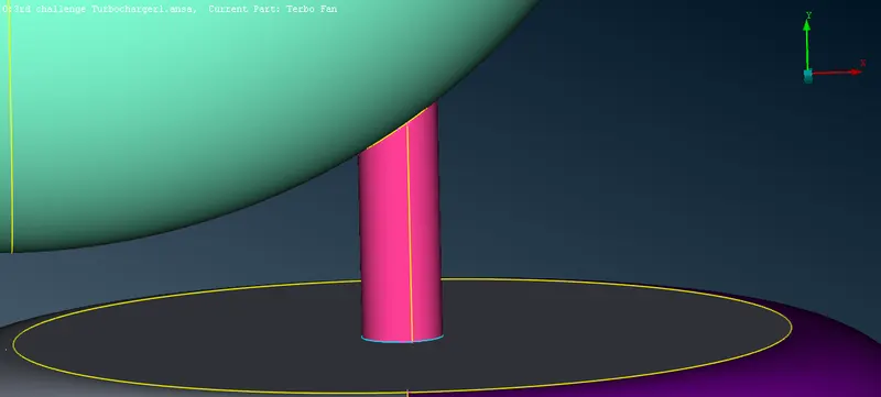
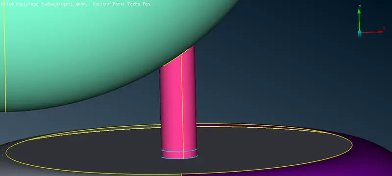
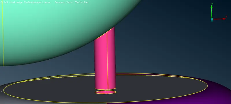
STEP - 11 : there is a triple con forming where the impellor and the rotor shaft intersect there is asurface inside the shaft and the impellor delete the sufaces and red cond formed in the impeller we have to project cons in the shaft to the impeler. cons>project>selet the and select the impeller area whree it can be projected do middle click or simply make cut between the hot points and dt f topo by selecting faces>topo. Now again do geomentry checks make sure there wil be no geomentrical errors in given model .
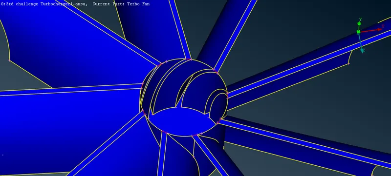
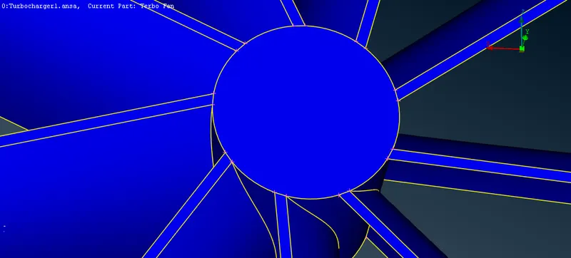
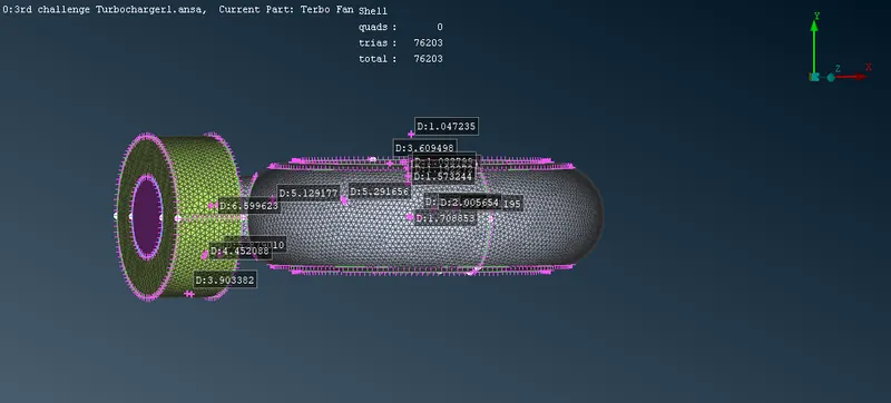
STEP - 12 : Before start surface meshing give PID and name the parts of turbo charger and close the all open part because we are going to do water type mesh for that we need a full closed model there will be no opening.First mesh the pressure valve casing it must be closed in the inlet and outet.target length given for mesing is 5mm. Go to mesh parameters give minimum target length as 3mm and maximum target length as 7mm and go to perimeters >length give length and macros as 5mm and go to mesh parameters click spot mesh >visible .
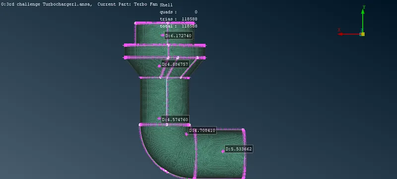
step - 13 : Mesh the turbo casing and inlet cover casing which has a same target length as 5mm . Go to mesh parameters give minimum target length as 3mm and maximum target length as 7mm and go to perimeters >length give length and macros as 5mm and go to mesh parameters click spot mesh >visible
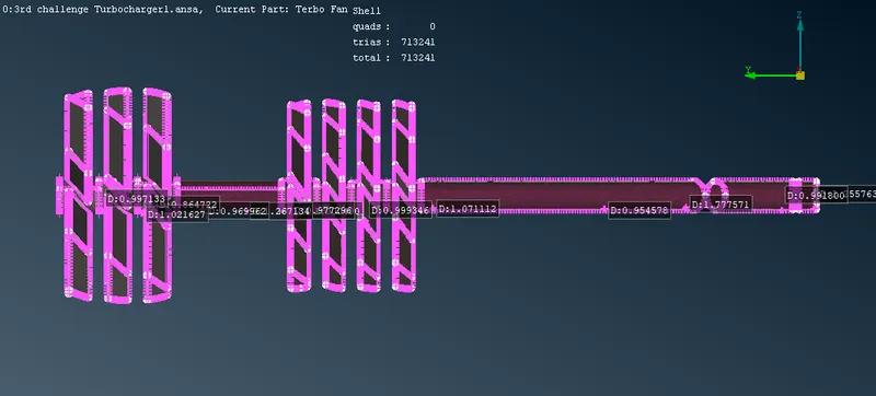
step - 14 : Mesh the shaft and the 1st and 2nd stage blades which also has a same target length as 1mm for that go to mesh parameters give minimum target length as 0.5mm and maximum target length as 2mm and go to perimeters >length give length and macros as 1mm and go to mesh parameters click spot mesh >visible .
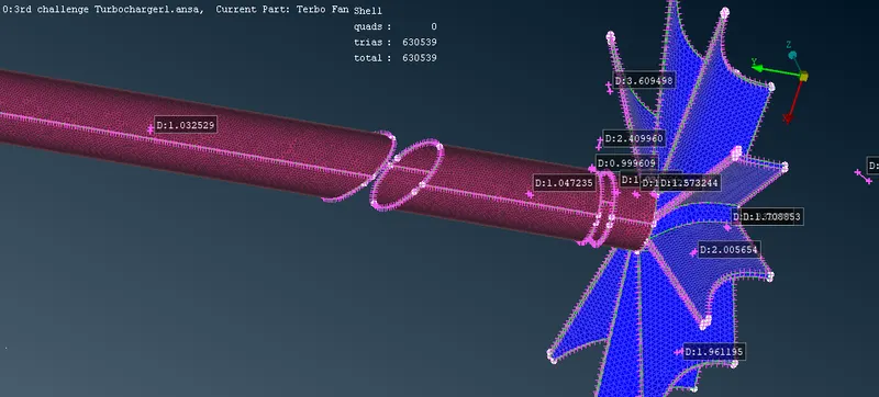
step - 15 : Mesh impeller with the target length of 2mm for that go to mesh parameters give minimum target length as 1mm and maximum target length as 3mm and go to perimeters >length give length and macros as 2mm and go to mesh parameters click spot mesh >visible.In here we can see some of the shafts mesh area is erased its due to the intersection of shaft area and the impeller which has two different mesh length so mesh the shaft area with mesh length as 1mm again some of meshed area of impeller is erased do the same. Mesh the erased area of impeller with target length 2mm.
STEP -16 :
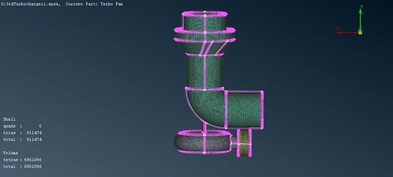
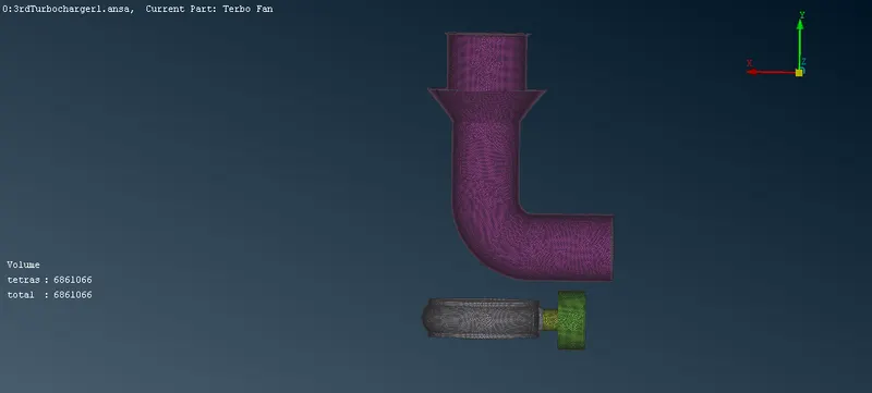
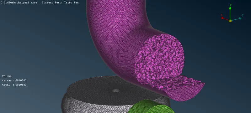
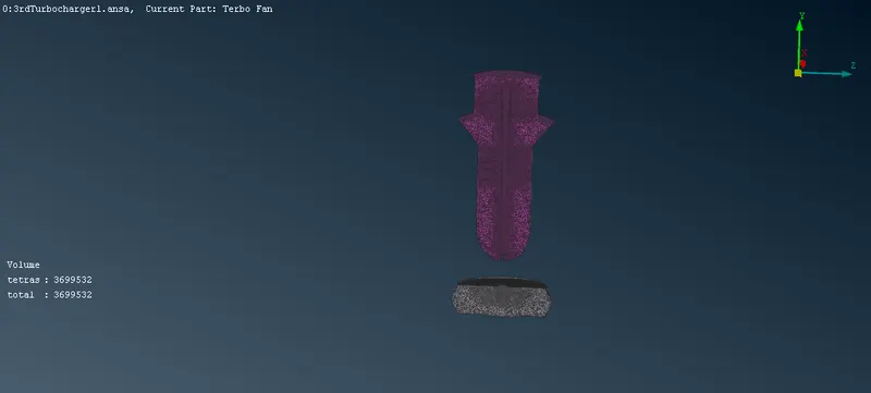
After completing surface meshing to all assigned PID with thier assigned target lengths we can now do volumetric mesh for that goto volumes>define >it will show a list of defined the volumes automatically in that we have to selet what are all need to be meshed and also delete unnecessary volumes, In the list show they are all unmeshed we need to mesh every yone of them one by one by right click one them>mesh before that we need to change the mesh type as tetra CFD by right clicking on types > modify>in list of mesh select tetra CFD. after meshing is done in tools bar down deselect the geomentry and select the volume .To the tetra mesh formed inside select>not>select any part it will show how the tetra mesh formed inside.
THINGS LEARNED:
1) To copy an surface by using transform option in the tools bar .
2) To project the curve by using curves>transform option inthe TOPO deck.
3) To create and assign PIDS.
4) To create a volumetric mesh by using classice mesh deck.
RESULTS:
The geomentrical errors in the given model is identified and cleared.The surface mesing of the different parts of the given model with different target length are also done and volumetric mesh can be done for the required volumes by using the classic mesh deck.