Week 3 Challenge : CFD meshing on Turbocharger
AIM :
To perform volumetric meshing for the required volumes of the turbocharger geometry.
OBJECTIVES :
1. Check for geometrical errors for the given model and perform topo clean-up for the same.
2. Create and assign PID’s for the various components of the turbocharger.
3. Perform surface mesh with the given target lengths as per PIDs and make appropriate volumes.
- Blade stage - 1 = 1 mm
- Blade stage - 2 = 1 mm
- Impeller = 2 mm
- Shaft rotor = 1 mm
- Turbo casing = 5 mm
- Compressor casing = 5 mm
- Inlet casing cover = 5 mm.
4. Generate volumetric meshing for the obtained surface mesh and write a detailed report on the surface meshing & volumetric meshing process.
INTRODUCTION :
A Turbocharger (often called a turbo) is a forced induction device that is used to increase the power of the engine or one can say the efficiency of an engine by increasing the amount of air entering into the combustion chamber, which is achieved by compressing the intake gas. More air into the combustion chamber means more amount of fuel will be admitted into the cylinder and as a result, one will get more power from the same engine if the turbocharger is installed in it.
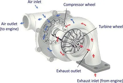
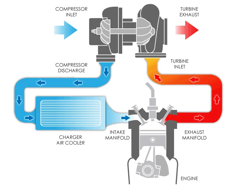
The turbocharger’s compressor draws in ambient air and compresses it before it enters into the intake manifold at increased pressure. This results in a greater mass of air entering the cylinders on each intake stroke. The power needed to spin the centrifugal compressor is derived from the kinetic energy of the engine’s exhaust gases.
PROCEDURE :
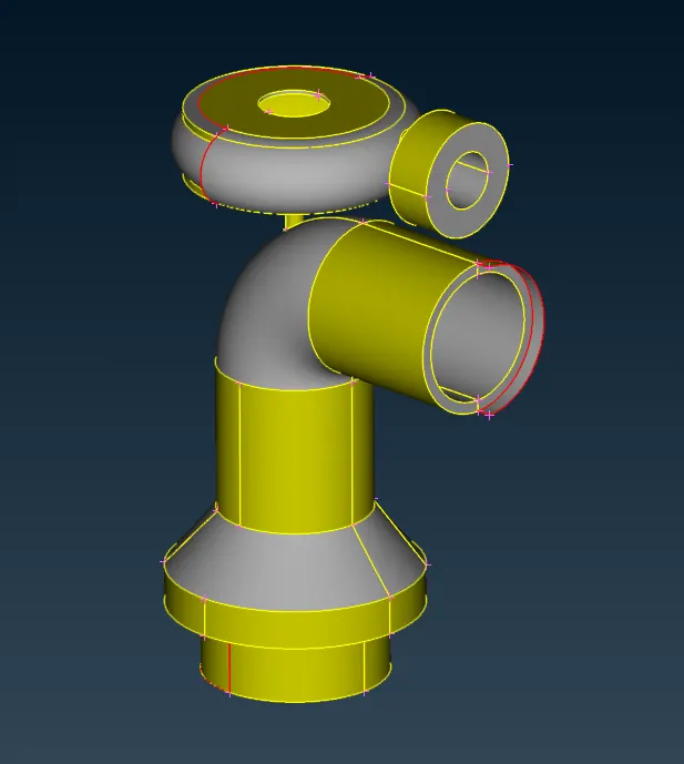
The first and foremost step is the process is importing the turbocharger geometry into the ANSA software. The imported geometry is as shown.
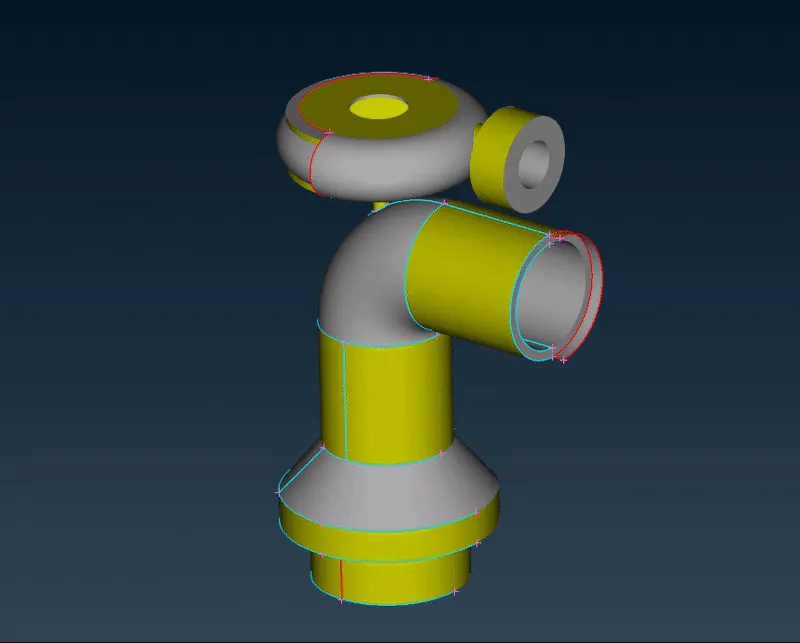
From the wireframe mode, we can observe that there are various errors present such as single CONS, missing surfaces, intersections and so on, which we need to resolve.
1. TOPO CLEAN-UP
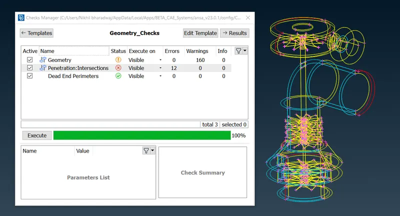
To resolve these errors and warnings, we perform topo cleanup for the geometry. Firstly, we run a geometry check to identify all the errors in the geometry, which we need to solve one by one.
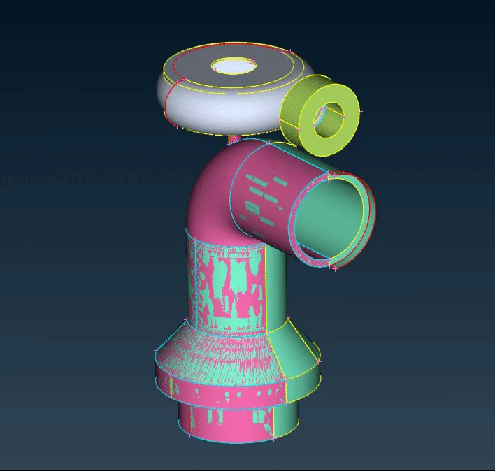
When we colour the geometry by PID’s, we can observe glitching on the compressor surface and triple CONS formed. This is an effect of overlapped surfaces. We need to resolve this by deleting the overlapped pink surface from the geometry and retaining only the green part. From the video shown, we can observe that the overlapped surfaces have been resolved.
2. RESOLVING SINGLE CONS
The next step is solving the various single CONS formed in the geometry.
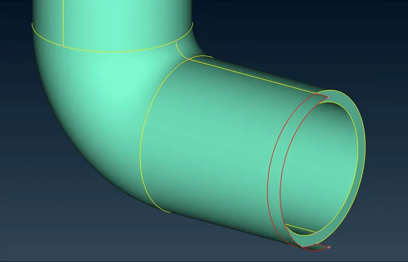
First, we are going to solve the single CONS formed by the extended surface near the compress outlet. To resolve this, we first delete the entire surface along with the extended part and then we create a new face, enclosed by the single CONS present as shown.
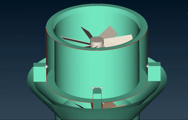
The next step is solving the single CONS near the compressor inlet. We do this by projecting multiple hot points from the lower edge, over to the top edge and thereby creating new hot points. Then, we individually connect these CONS to form new surfaces as shown.
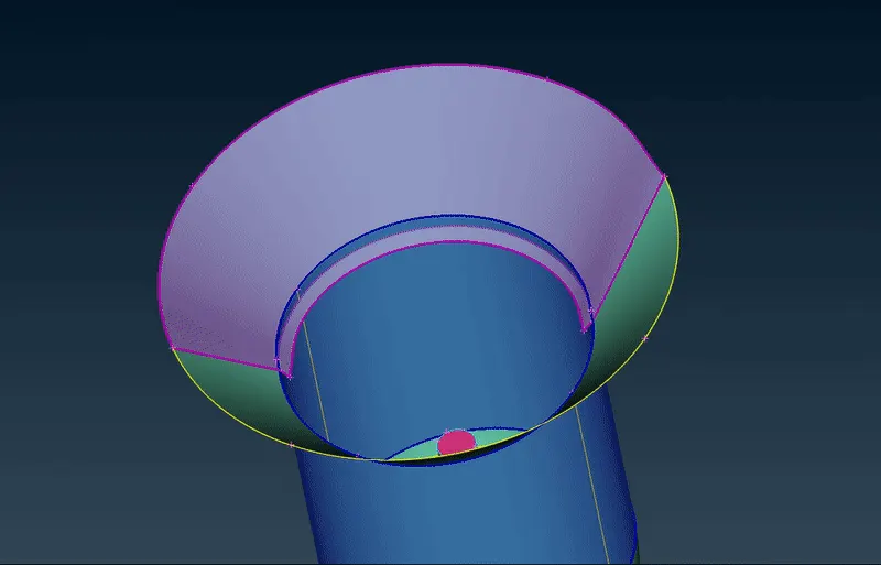
The next step is solving the intersection error at the conical section of the compressor. We use the intersection function to delete the unnecessary faces of the intersected parts and keep the faces which we require. The intersected surfaces are thereby solved as shown.
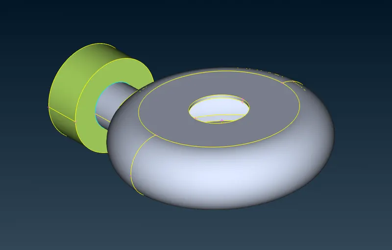
The final single CONS we are going to resolve is the impeller casing. To resolve this, we are going to use the “transform (copy)” option to copy the back half part of the impeller to the front, on a 3 point mirror plane. Then we use the ‘fill hole’ function to obtain our completed impeller casing surface as shown.
Thereby, we have successfully solved all our double CONS errors and we can cross check that by viewing the wireframe of the geometry. Further, we move on to solve the triple CONS present.
3. SOLVING TRIPLE CONS
In this step, we solve the various triple CONS present in the geometry, either due to overlapping of surfaces or a generic triple CONS. First, we need to identify which triple CONS are needed and which are not.
From the wireframe mode, we can see that these are the triple CONS currently present in the geometry.
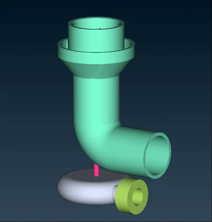
The triple CONS formed near the inlet case cover of the impeller is formed due to the joining of three surfaces. Therefore, we do not delete this triple CONS as it is not an error.
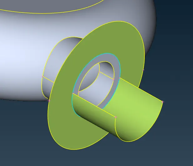
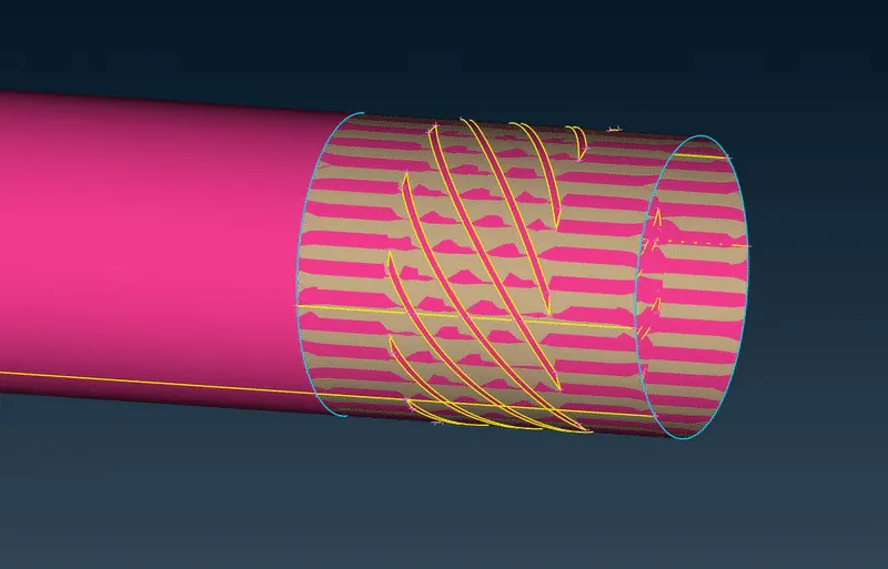
Next, we move on to solve the triple CONS formed along the rotor shaft. This is formed due to the overlapped surfaces, which divides the blades into separate volumes. By removing these surfaces, we are going to be solving the triple CONS error as well as obtain the blades as a single volume. We repeat this step on all the junctions of the blades till all the triple CONS are resolved and each stage of the blades are obtained as a single volume.
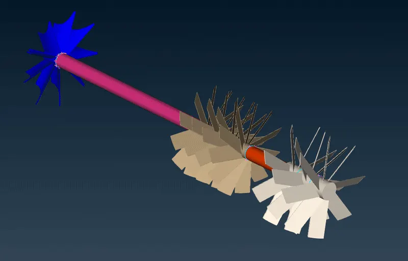
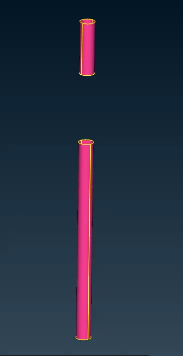
To solve the overlapping surfaces on the shaft part of blade stage – 2, we first project the CONS on the rotor shaft surface and thereby, separating the surfaces from the shaft. We then hide the grey surface (blade) and we delete the overlapping pink surface.
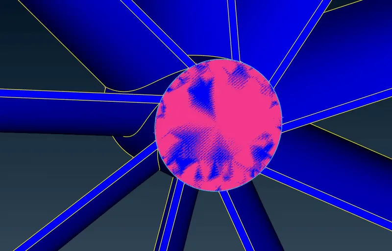
Finally, to solve the triple CONS on the surface of the impeller, we first need to project the CONS from the surface of the shaft onto the impeller surface, so as to obtain connectivity between the blades. After doing so, we can successfully delete only the overlapped surfaces as shown.
Thereby, we have successfully resolved all the single and triple CONS from the entire geometry and we further move on to assigning the PID’s to the respective components.
4. ASSIGNING PID’s
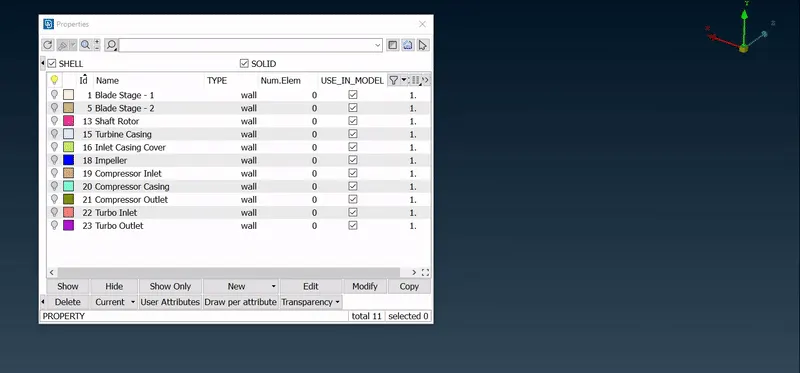
In this step, we assign the respective PID names to the respective components of the turbocharger. The various components of the geometry are as follows.
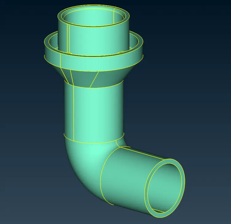
i.) Compressor Casing
The compressor housing converts the high-velocity, low-pressure air stream into a high-pressure, low-velocity air stream through a process called diffusion. The compressed air is pushed into the engine, allowing the engine to burn more fuel to produce more power.
ii.) Turbo Casing
The job of the turbine housing is to guide the exhaust gas into the turbine blade.
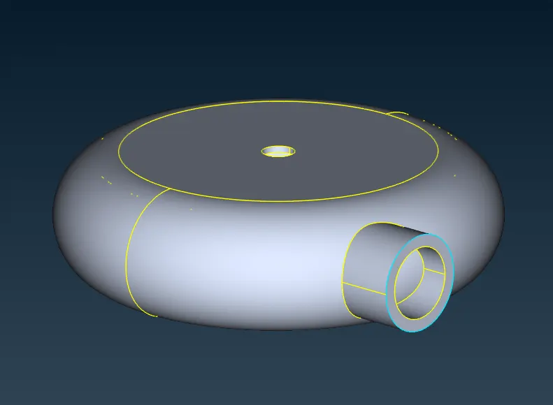
iii.) Inlet Casing Cover
This component is attached to the turbo casing and it makes sure that there is no leakage of the exhaust gases into the surroundings. It provides a fitted path for the flow of exhaust gases into the turbine.
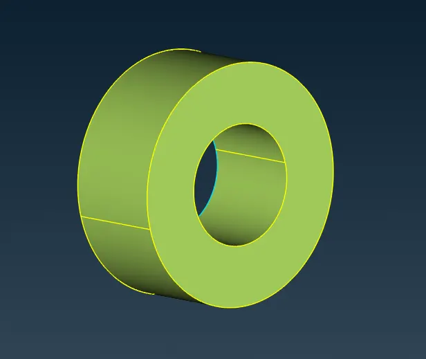
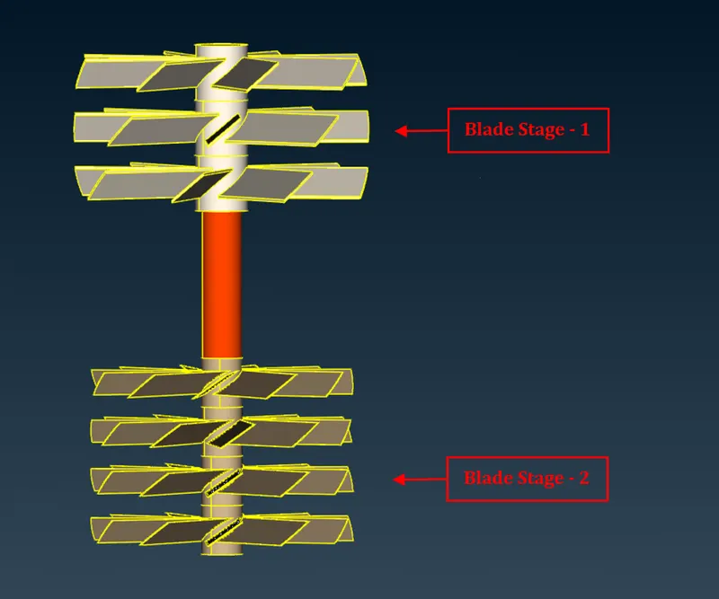
iv.) Blades
The mode of action of the compressor blades is opposite to that of the turbine blades. As the turbine turns the compressor blades, the high-velocity spinning draws in air and compresses it.
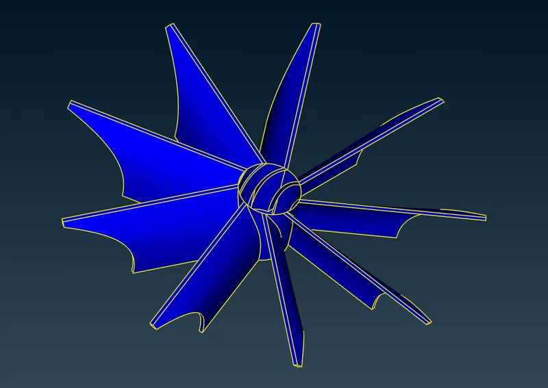
v.) Impeller
The energy from the exhaust gas turns the turbine wheel or the impeller, and the gas then exits the turbine housing through an exhaust outlet area.
vi.) Shaft Rotor
The compressor wheel is attached to the turbine by a forged steel shaft.
Therefore, the respective PID’s have been assigned to the components of the turbocharger along with their colour codes.
5. CLOSING THE GEOMETRY
Before moving on to the meshing part, we need to make sure that there are no open surfaces throughout the geometry and thereby, we need to close them in order to obtain volumetric meshing.
To do so, we first create planar surfaces over the inlets and outlets of the compressor and the turbo as follows. We also assign their respective PID’s as the compressor inlet & outlet as well as the turbo inlet & outlet. The final closed geometry and their PID’s are represented as follows.
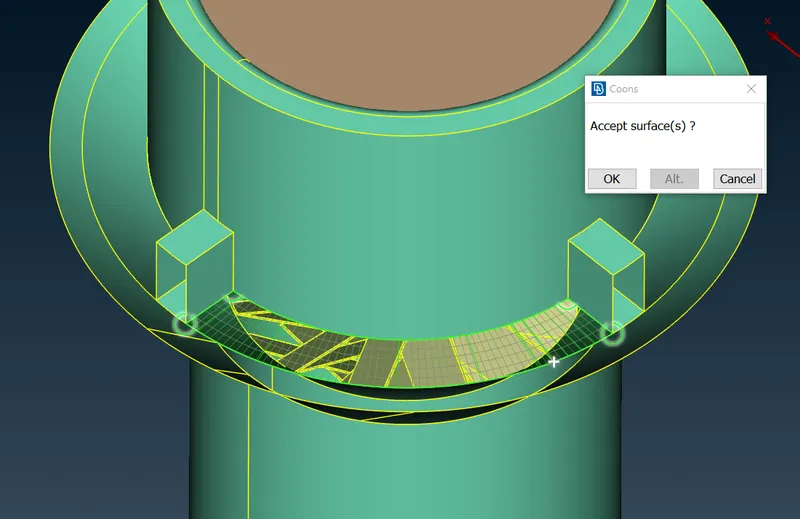
Also, we can observe that there are gaps around the compressor inlet, which we need to seal off before meshing. Thereby, we create new COONS surfaces to cover them up as shown.
6. SURFACE MESHING
After the respective PID’s have been assigned and geometry has been closed, we then move on to generate surface meshing for the geometry.
Firstly, as per the challenge requirement, various components of the geometry are provided with different target lengths. Thereby, we group the components together according to their mesh lengths.
Group – 1 : Turbo casing, Compressor casing and Inlet casing cover = 5 mm Target Length
In order to mesh these components for a target length of 5 mm, we first isolate them separately and we provide the perimeters and macros length as 5 mm. We also provide our quality criteria parameters of minimum length as 4 mm and maximum length as 6 mm, so as to maintain the generated mesh within that range.
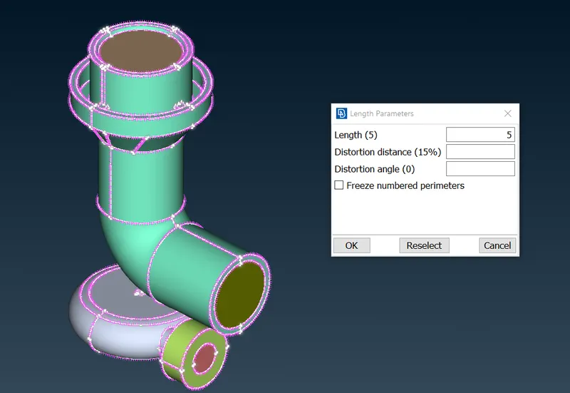
We generate tria CFD meshing for these components and we finally freeze them, such that there is no change in these components during meshing of the other components.
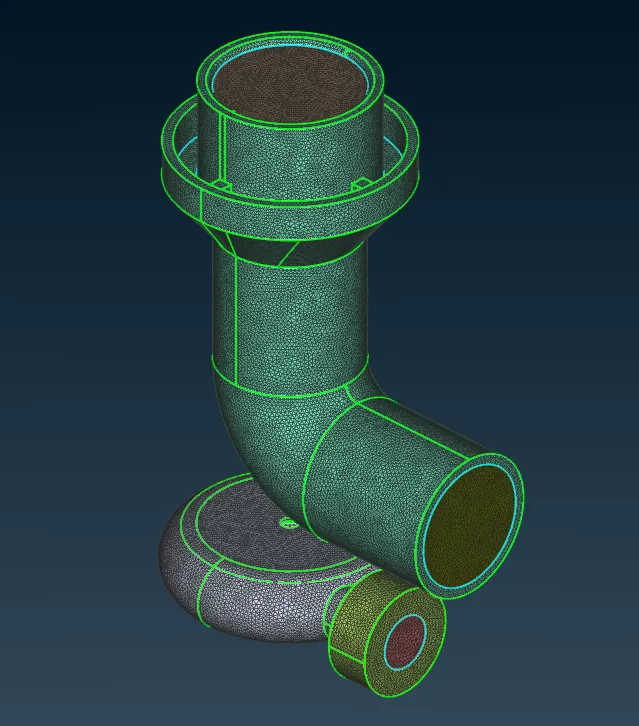
Group – 2 : Impeller = 2 mm
Firstly, we provide the perimeter and macros length as 2 mm for the impeller geometry by isolating it. Also, we provide the quality criteria as 1 mm for minimum length and 3 mm for maximum length such that we obtain meshing within that range.
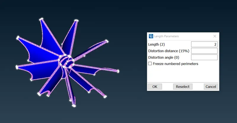
Finally, we generate tria CFD meshing for the geometry and we freeze it as well.
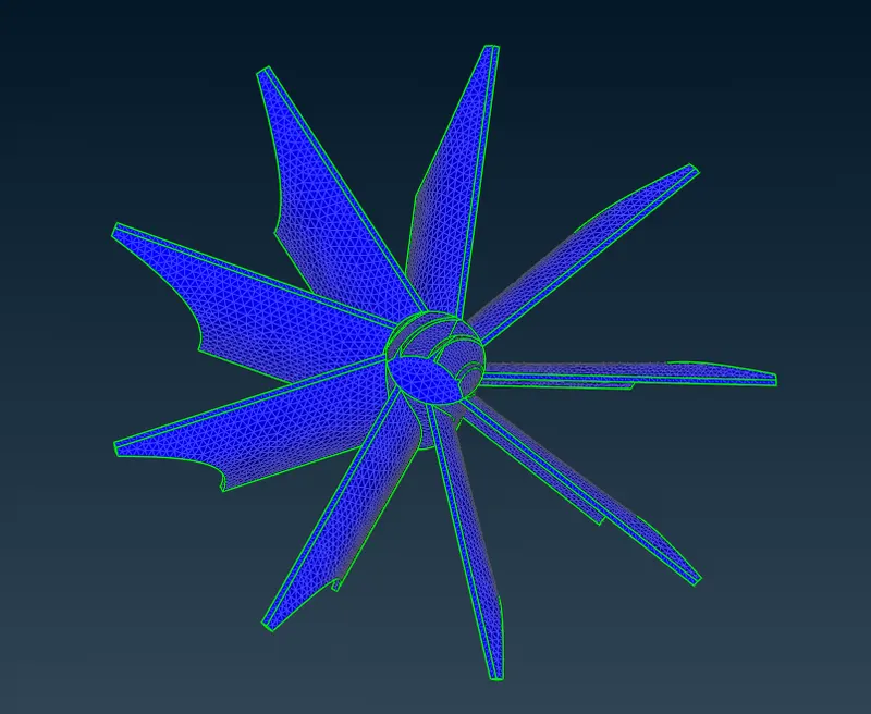
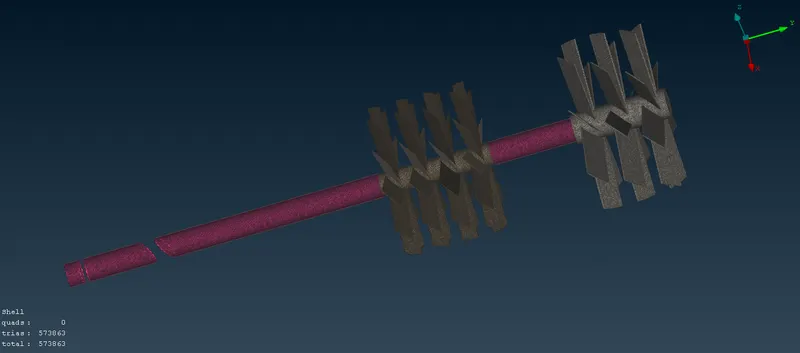
Group – 3 : Blade stage 1 & 2, Shaft rotor = 1 mm
For these components, we provide a perimeter and macros length of 1 mm. Also, we provide the quality criteria parameters of minimum length as 0.3 mm and maximum length as 1.5 mm, so as to narrow down the range.
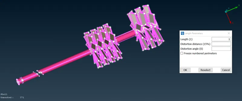
Thereby generating tria CFD meshing, we obtain our final geometry as follows.
7. VOLUMETRIC MESHING
In order to generate a volumetric mesh, we first need to generate a surface mesh. Surface meshing is the pre-requisite for volumetric meshing.
Before moving further, we first need to define the volumes (i.e., the inner regions) of the whole database, by using the define function. From the auto volumes detected, we filter out the inner volumes of the geometry and we delete the rest as shown.
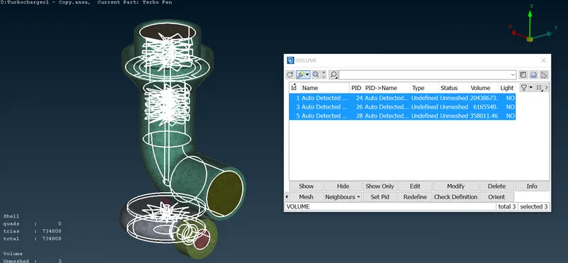
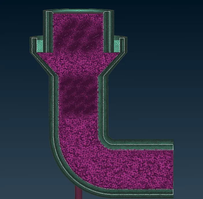
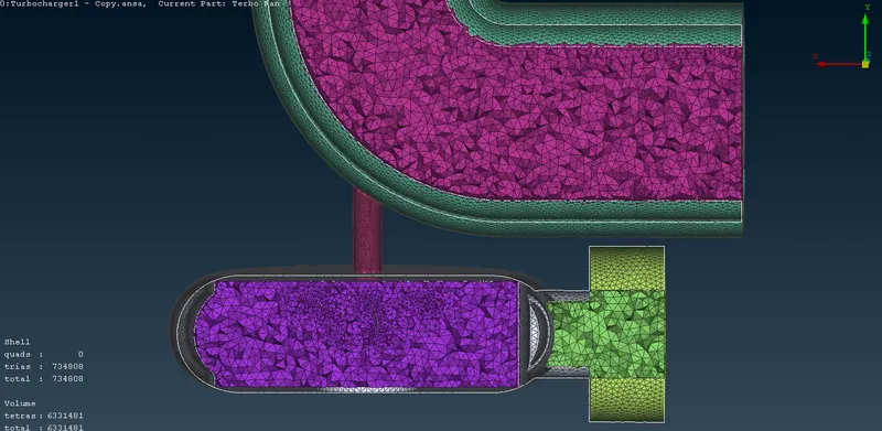
We have therefore isolated the inner volumes of all the geometries as shown above. For these volumes, we generate a tetra CFD meshing, with reference to our obtained surface meshing. In order to visualize the volumetric meshing generated for the geometry, we create a cut plane on the default x-y axis, so as to split the geometry in half as shown.
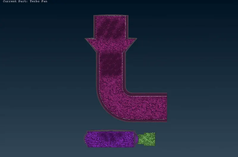
`360^o` View of Volumetric Meshing :
Turbocharger Model File : https://drive.google.com/file/d/1-Qi_F3tI7gepdOjpt8N8sY6veOl2xtqE/view?usp=sharing
CONCLUSIONS :
The geometrical errors such as single CONS, triple CONS and intersection errors in the geometry have been solved using various tools and have been explained in detail.
The tetra CFD volumetric meshing for the turbocharger model has successfully been achieved by performing surface meshing of different target lengths for the various components of the geometry as shown above.