Week 3 Challenge : CFD meshing on Turbocharger
CFD MESHING ON A TURBOCHARGER
Aim;
To do CFD meshing of the turbocharger with given parameters.https://drive.google.com/file/d/17Ewfjanwgv5_2MEeGHAAB9ZtPPbOAHXj/view?usp=share_link
Procedure;
Stage-1; Topological cleanup
file > open file
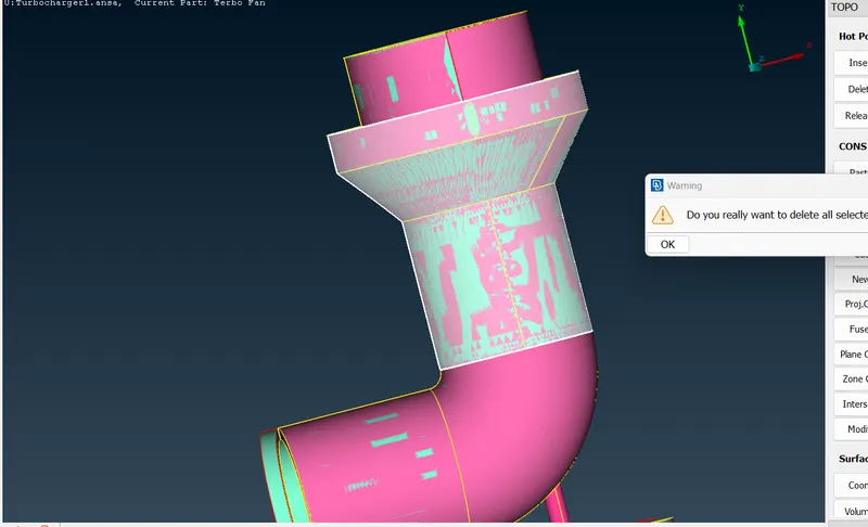
Look for any overlapping surfce by finding gliching's on the surface (or) by geometrical checks.
Delete > select the face > middle click
continue the same for all the surface use (or)(add)(not) options for selecting the surface which are overlapped with other.
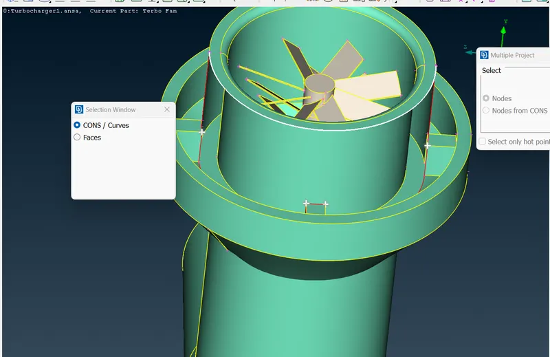
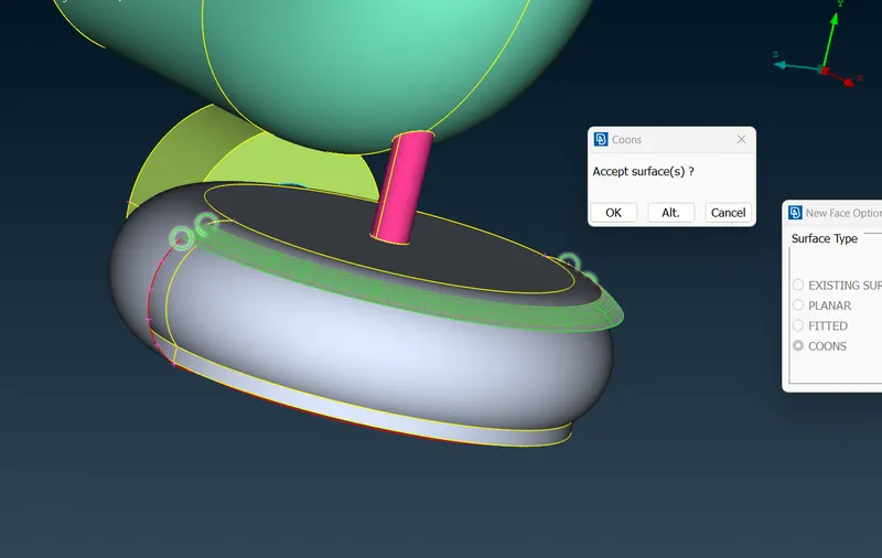
In case case of surfaces like this we can't create faces in oneshot because the geometry won't get proper so we need to create surface by creating same surfaces.
Hotpoint >multi. project >nodes(select hot points) > middle click >select cons/curves.
faces > new >select cons >surface type >middle click >ok
in case of the turbo casing we first we need to create hotpoints
Hotpoints >parametric >0.5 as distance >select the cons & direction
faces> new >surface type >select cons >(choose suitable alternative)ok
check for any single cons left after that by geometry checks (or) wire frame.
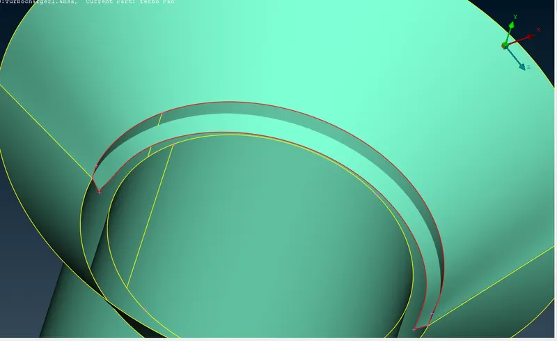
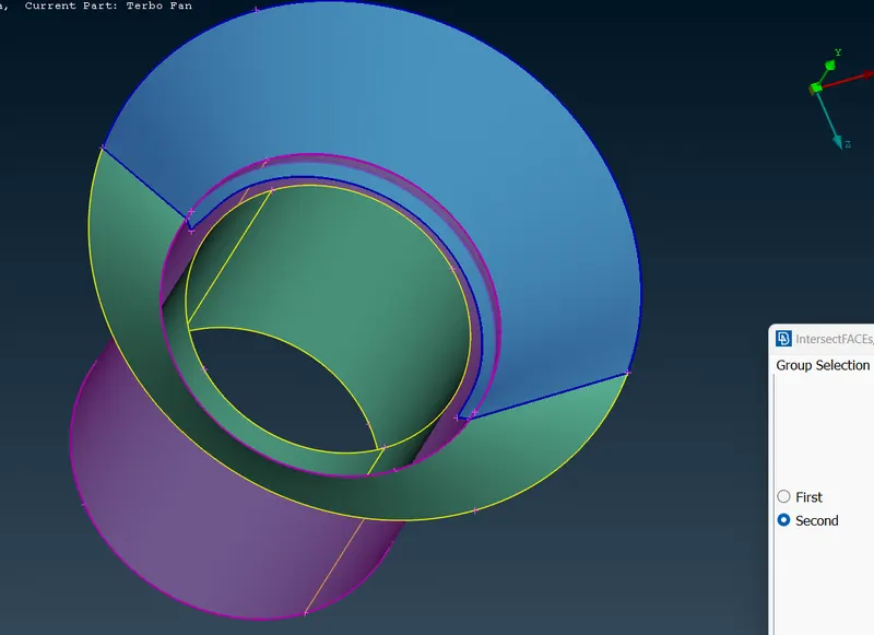
in this are one face is penetrated through another so;
faces >intersect >first (middle click)>second(midddle click) >ok
delete the unwanted face .
Before doing volumetric mesh we should ensure model should have one volume ,delete unwanted faces which create different volume .
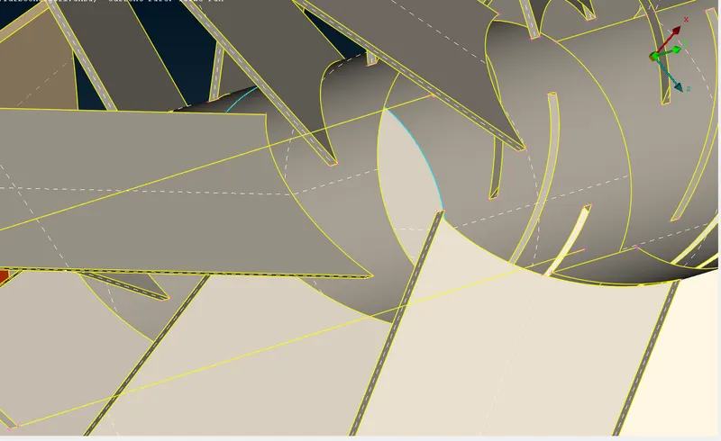
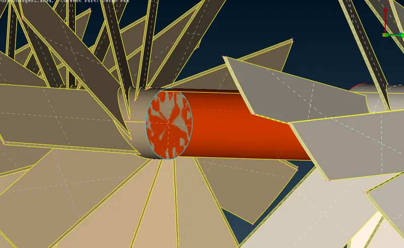
after finishing topological cleanup assign PID'S for different parts.
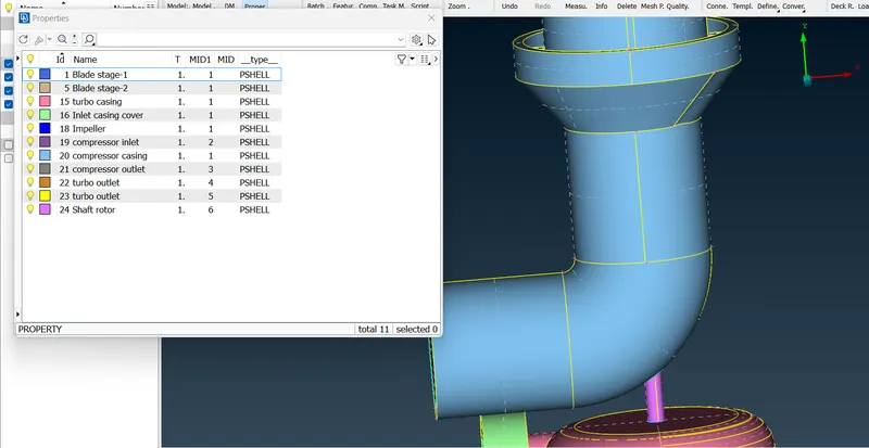
Stage-2: MESHING
Meshing one by one with given target length
Compressor casing;
perimeter > length > perimeter > middle click(5mm) >macros (5mm) > ok
mesh parameters > general > tria >target length (5mm) > minimum length(3mm) > ok
quality criteria > min. length(3mm ) > max.length(7mm) > ok.
spot mesh > select> middle click.
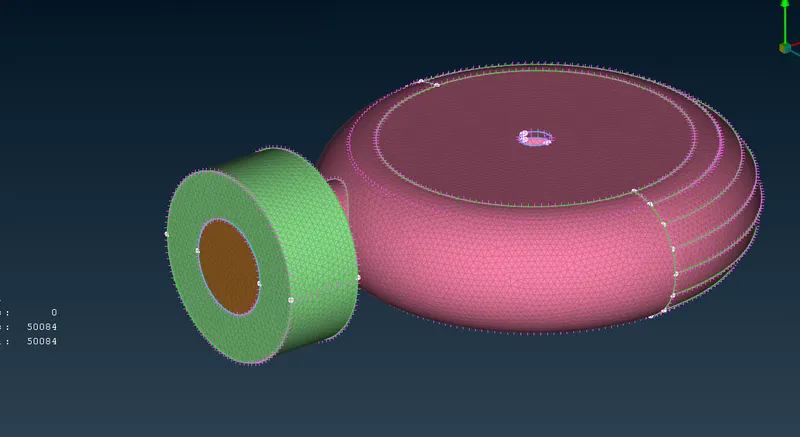
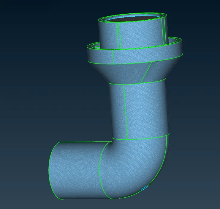
Turbo casing & inlet casing cover;
perimeter > length > perimeter > middle click(5mm) >macros (5mm) > ok
mesh parameters > general > tria >target length (5mm) > minimum length(3mm) > ok
quality criteria > min. length(3mm ) > max.length(7mm) > ok.
spot mesh > select> middle click.
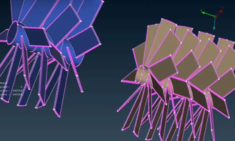
Blade stage -1 & stage -2;
perimeter > length > perimeter > middle click(1mm) >macros (1mm) > ok
mesh parameters > general > tria >target length (1mm) > minimum length(0.5mm) > ok
quality criteria > min. length(0.5mm ) > max.length(2mm) > ok.
spot mesh > select> middle click.
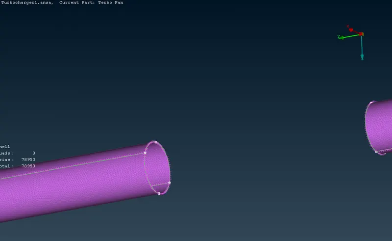
Shaft rotor ;
perimeter > length > perimeter > middle click(1mm) >macros (1mm) > ok
mesh parameters > general > tria >target length (1mm) > minimum length(0.5mm) > ok
quality criteria > min. length(0.5mm ) > max.length(2mm) > ok.
spot mesh > select> middle click.
In some areas mesh element are mesh because of the Mesh length varying with PID'S so we need
select macrcos and perimeter in varying mode (eg 1-5 target length) the apply spot mesh again.
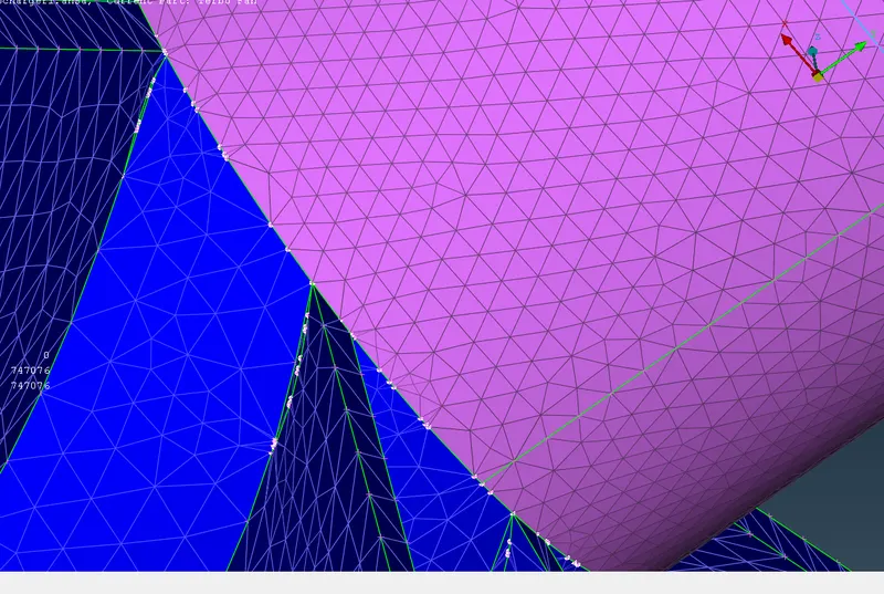
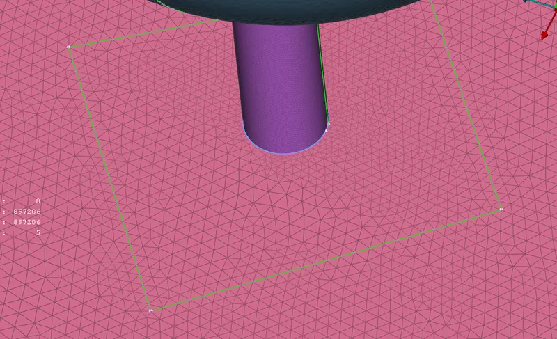
draw a line very varying meshlength which will keep the varying mesh length will keep in that surface.
face > cut > reconsturct > drag the line > right click
Stage 3- volumetric mesh;
volume >define (whole db)
auto identified volumes by ans will appear.
select only volume we don't geometry thickness volume.
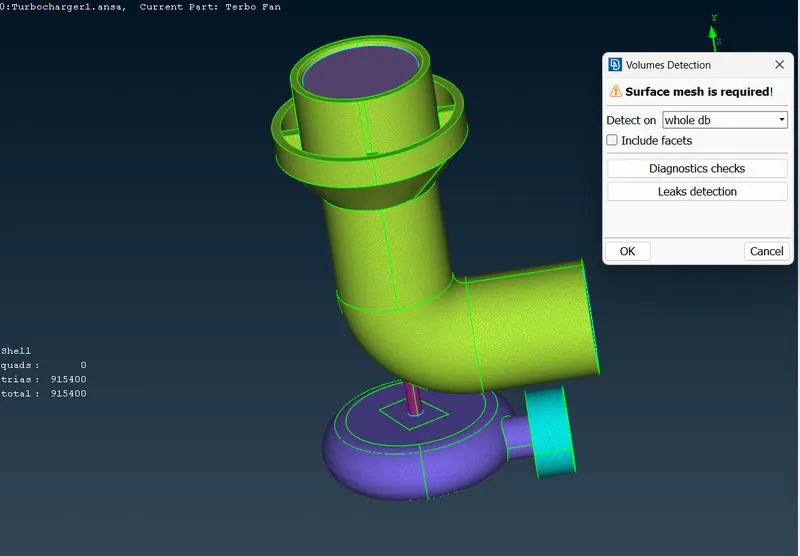
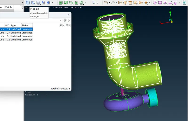
volume > detected volume > remesh > tetra CFD.
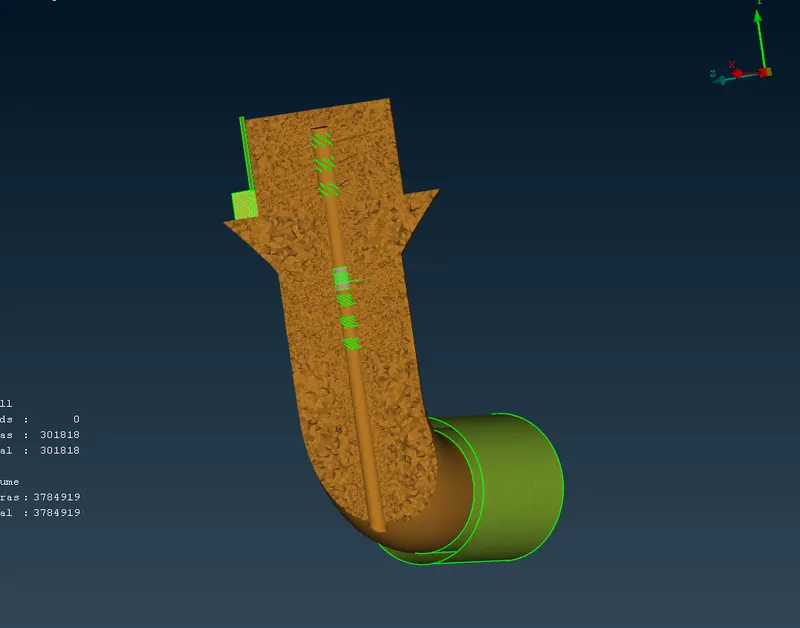
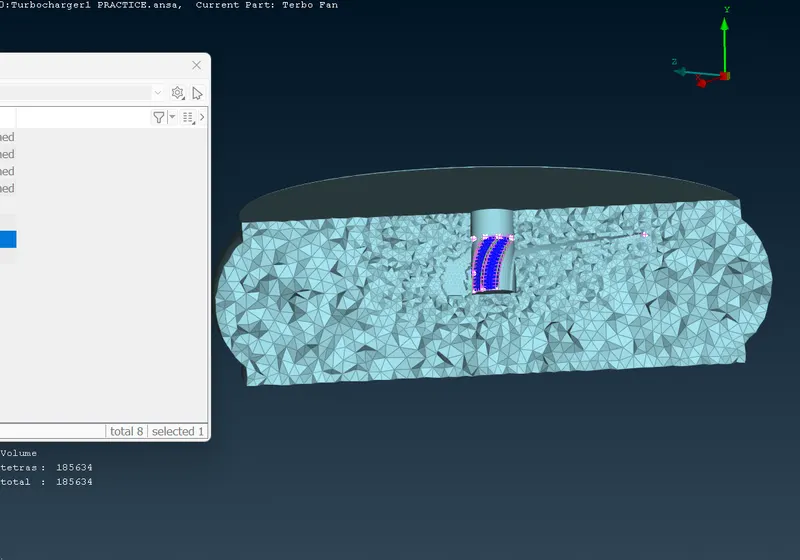
Chech volumetric mesh by hidding the cross section.
LEARNING OUTCOMES;
By doing the CFD mesh on turbocharger will be knowing about;
- topological cleanup of complex surfaces.
- create surfaces by creating small surface without affecting geometry.
- Assigning PID'S for different parts.
- which all the volumes are not required for volumetric mesh.
- auto detecting of volumes.
- volumetric meshing of a meshed surface.
RESULT;
We got CFD Meshing on a turbocharger with required parameters.
CONCLUSION;
If the component have one volume and the surface mesh of component is complete we will get a proper volumetric mesh with required criterias.
https://drive.google.com/file/d/17Ewfjanwgv5_2MEeGHAAB9ZtPPbOAHXj/view?usp=share_link