Project 1 : CFD Meshing for Tesla Cyber Truck
CFD MESHING FOR TESLA CYBER TRUCK
AIM; https://drive.google.com/file/d/1pi2XkjuzTrC9ERgF5lDgqFdwIFwMdudv/view?usp=share_link
To do CFD meshing on a tesla cyber truck with suitable element criteria.
Procedure; Step1-Topological cleanup
File > open > project 1 cyber truck.
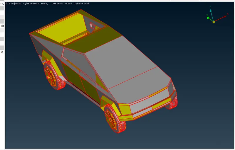
Here we can see lot of single cons,for removing single cons ,do topo.
Face > topo > box selection >middle click.
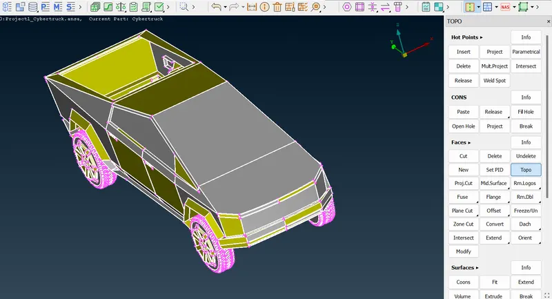
Lot of missing surface and unwanted surface can be found'
Create the missing surface by fill hole or faces > new
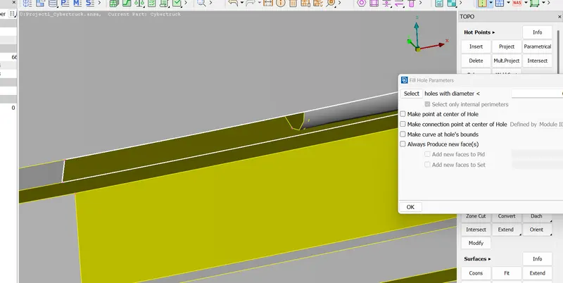
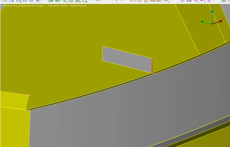
Delete the unwanted surface using delete option.
Before doing further topological cleanup for easy and less time consuming for that we can make a cut in the middle on the whole model and delete one half.After finishing upto meshing ,later we can transform the existing other half.
For cutting through the middle we need a mid point to place the plane cut.
we can take mid point by;
Hot points > parametrical > 0.5 > select cone & direction > ok.
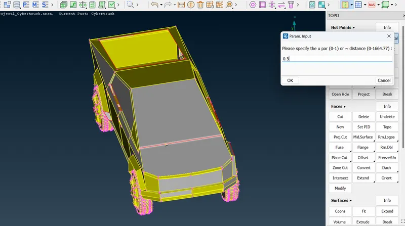
After that do perimeter > length > perimeter & macros (1mm) > (to increase the resolution of the given model)ok.
For doing plane cut.
Face > plane cut (Single )> select the hot point >middle click > yes.
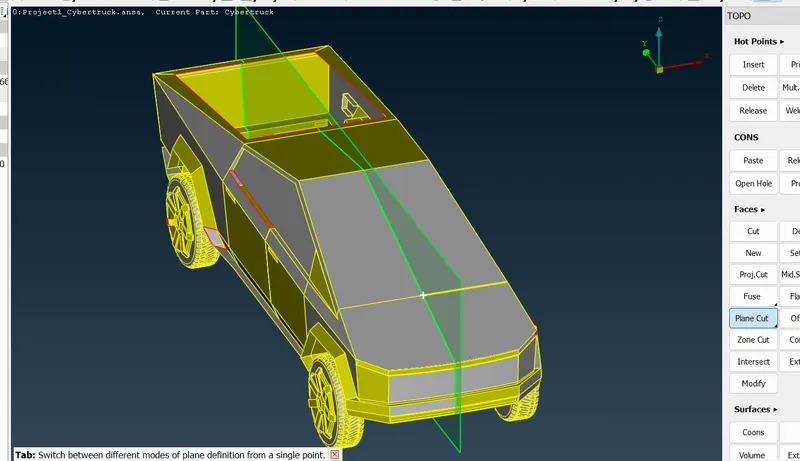
After that delete the half entity .
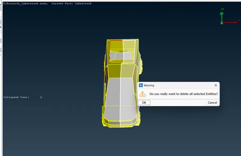
Continue the topological cleanup in this existing entity .
Delete the overlaping surface & delete the unwanted surface inside the car which create another volume during volumetric mesh.
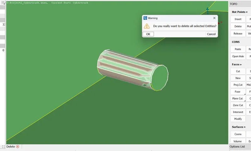
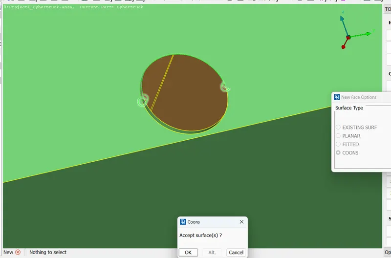
Here, now the wheel part & body have sigle volume.
After that go for geometric checks
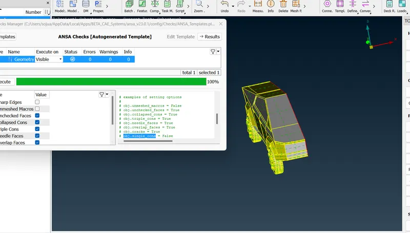
Checks > geometry > select all the values > execute.

Resolve the geometrical problems.
Delete unncessary cons which create problem during meashing and create new ones.
checks for any unwanted single cons by turning off all the double cons,triple and turning off the shadow mode.
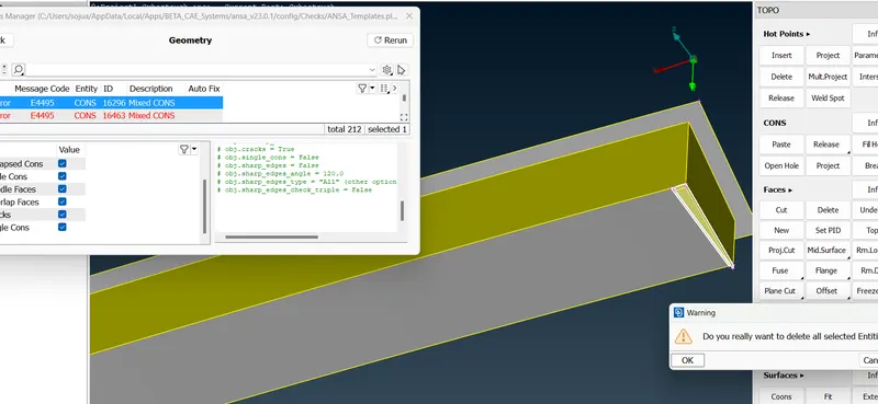
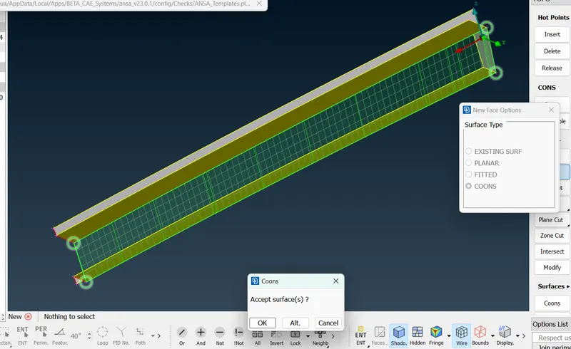
Also Check the geometry again to conform there is no geometrical errors.
Step-2 Assign different PID'S:
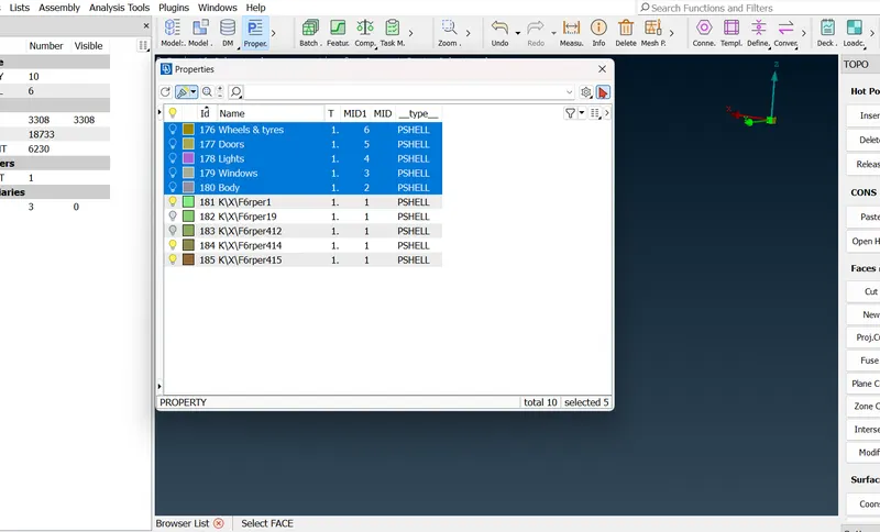
Here i have created this much pid's.
assign one by one .
select the property (wheel & tyres) > right click > apply.
isolate the wheel & tyres by ( !-not) in ENT mode.
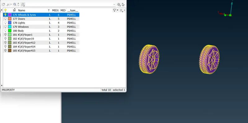
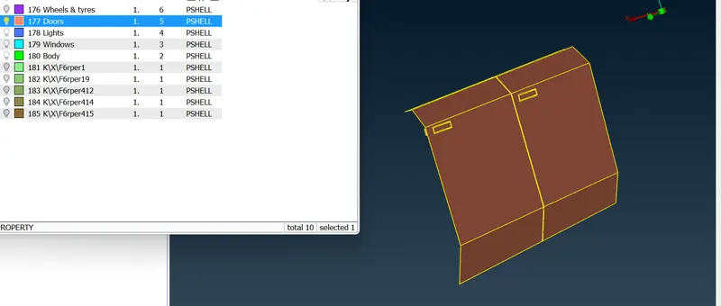
Continue the same step for all other pid's.
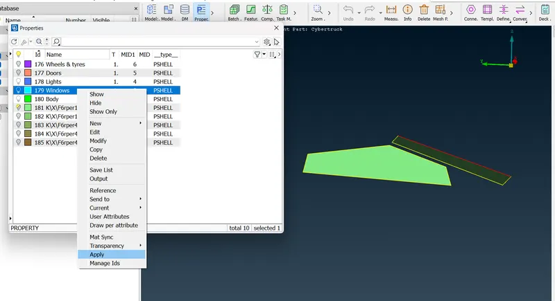
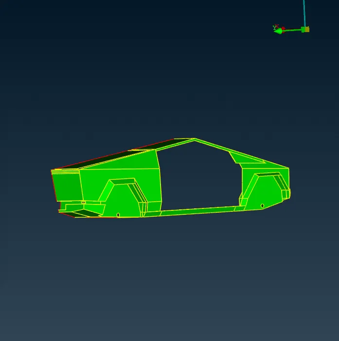
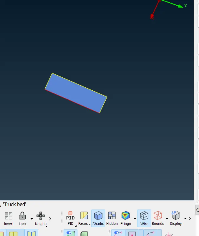
To delete unwanted proprties we use compress option > ok.
Step-3; MESHING.
Before meshing we need take measure of the smaller region inorder for the reference of min length & max: length.
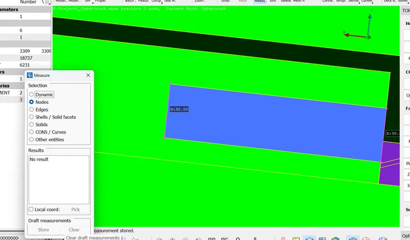
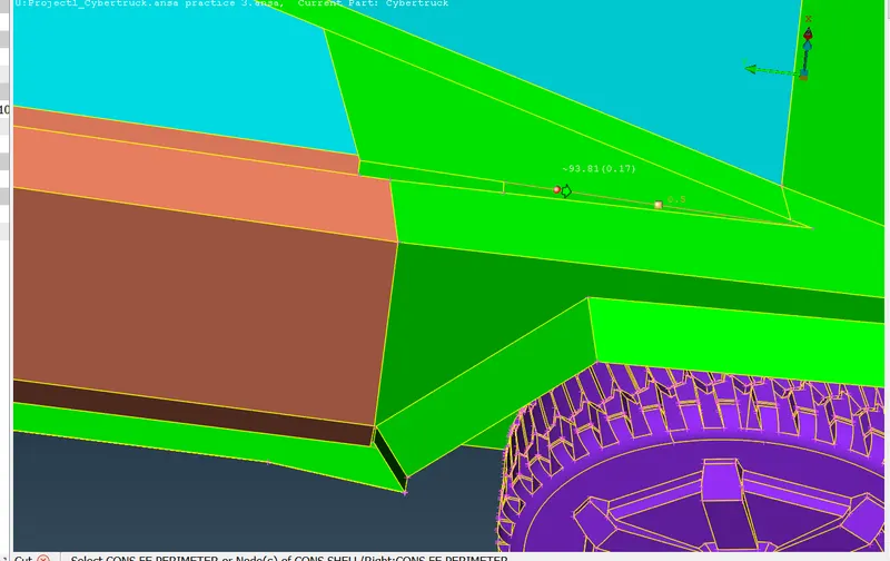
also cut the planes which are closer and not necessary.
| PID'S | Min: length | Max: length | Target length |
| Wheels & tyres | 1 | 4 | 2 |
| Doors | 2 | 5 | 3 |
| Windows | 2 | 5 | 3 |
| Body | 0.5 | 5 | 4 |
| Ligths | 2 | 4 | 3 |
| Truck Bed | 2 | 5 | 4 |
Meshing part by part;
Isolate the wheels & tyres by proprties show only then apply lock.
Quality criteria>
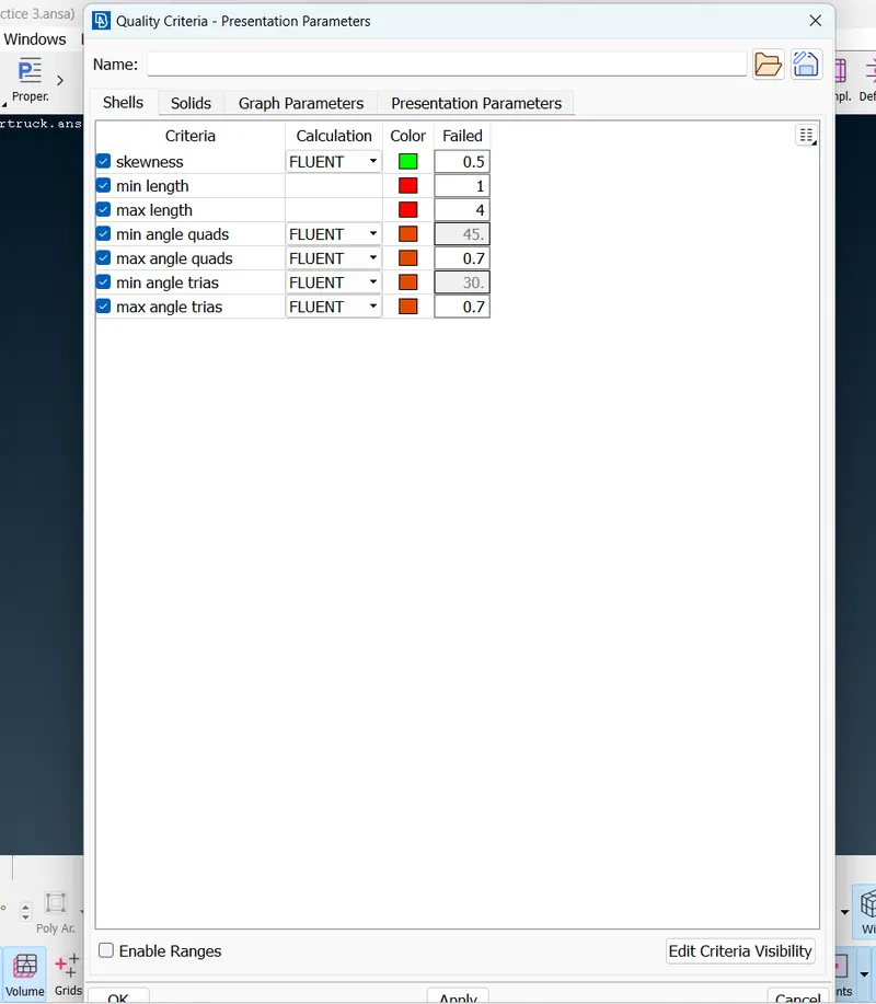
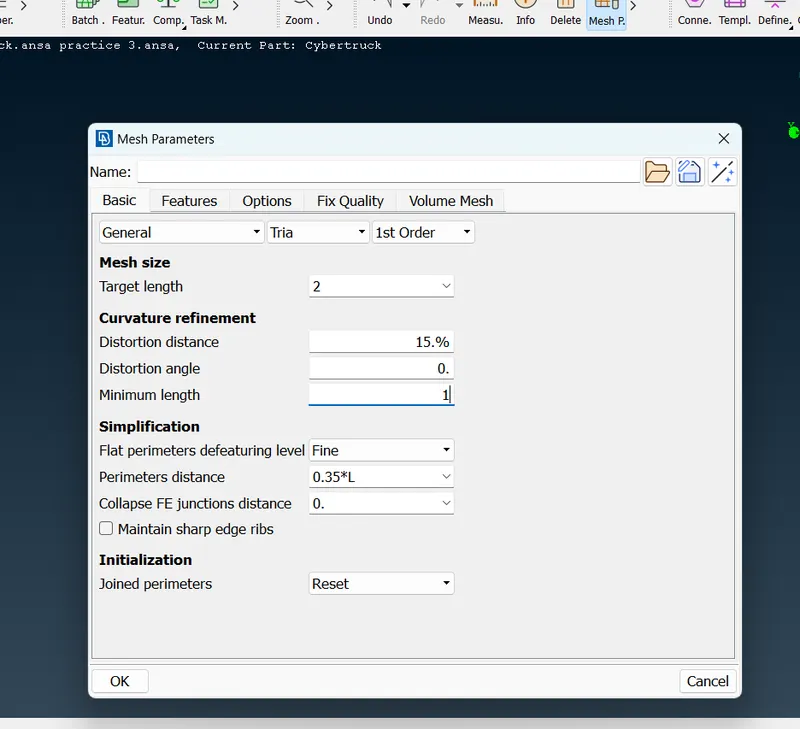
Enable all this option & put max: & min value.
here, maximum is 4mm & minimum is 1mm.
Mesh parameters > target length > (2mm) > minimum length ( 1mm) > enable (tria ) > ok.
perimeter > length > perimeter ( 2mm) > macros (2mm) >middle click.
Mesh generation > spot mesh > visible .
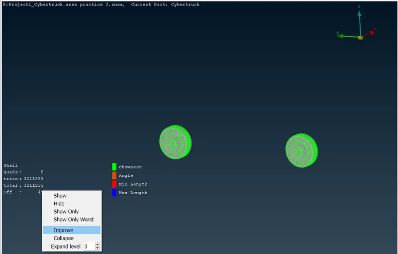
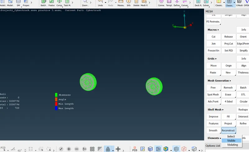
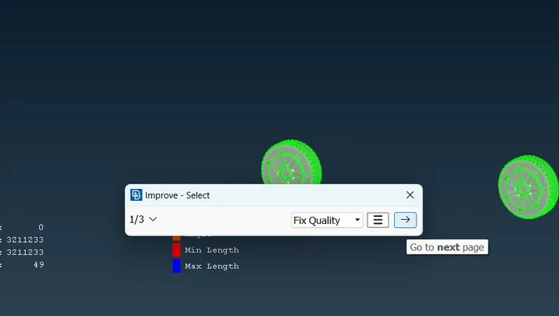
Enable the hidden mode to see the off elements. If there is off elements present use reconstruct > visible .
Also their more elements left we an use improve option by right clicking on off element
Improve > ( we can select quality,smooth,reshape ,reconstruct) use accoding to which tool helps to avoid off elements.
Continue the same procedure for all other PID'S except body pid.
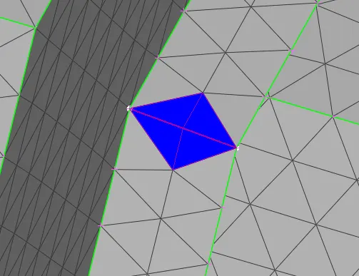
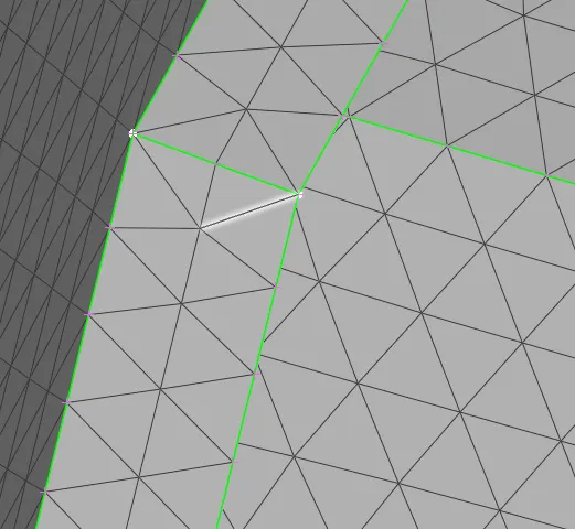
In some cases we need resolve the off elements manually in that we can use tools like paste,move , split etc.
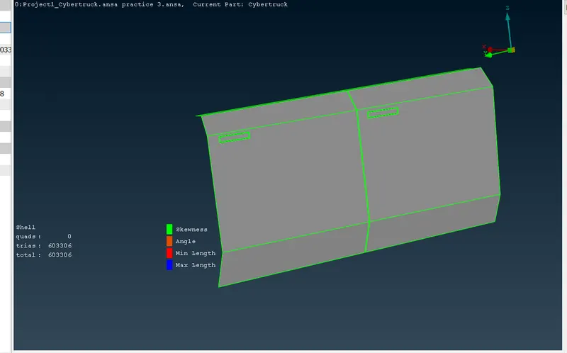
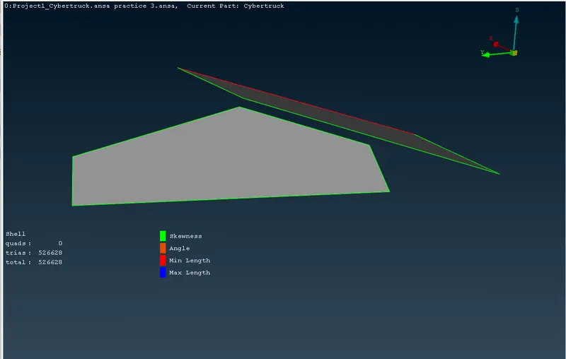
After conforming meshed part have no off element ,Go for body PID
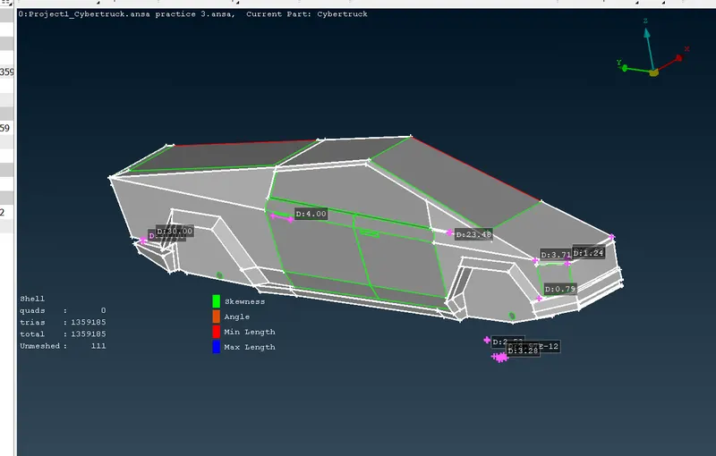
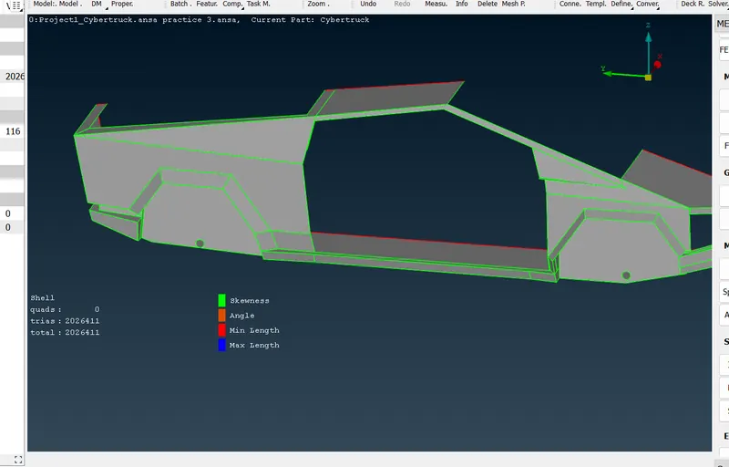
For meshing body PID's the procedure is little bit tricky because Body PID shares with other PID's which have different mesh length so we need deselect the perimeter which shares with other PID region otherwise mesh won't be proper.
After assigning quality criteria and mesh parameters.
Length > perimeter(4mm) (deselect all the perimeter shares with other pid's) >ok
STEP-4; Transform
After meshing ,we can trenasform or copy entity to do symmetry .
Set the view in left view which will give a proper idea.
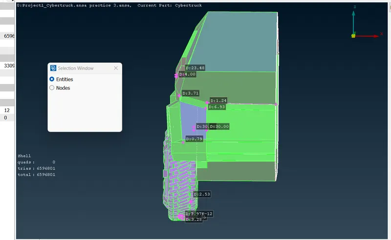
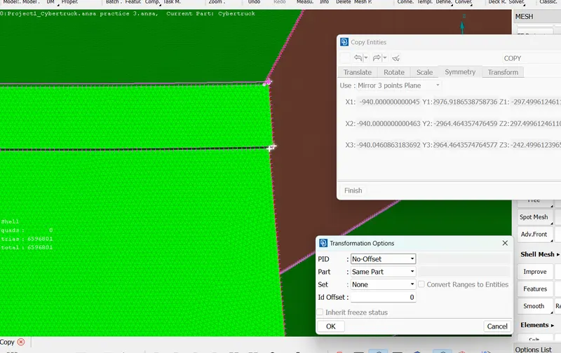
Transform > copy > entities > box selection > middle click > symmetry > mirror 3 point plane (select three point in one plane )> middle click > PID(No offset) >part(same part) >set(none) >ok.
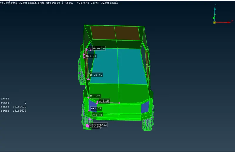
STEP-5 WIND TUNNEL;
First ,to create bottom surface we need a center point of the model.
for that parametrical > select cons > 0.5 > ok
the create a point in the bottom
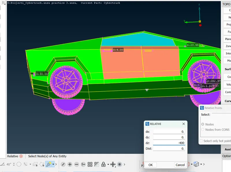
Relative > select the node > middle click > take -400mm in dz > ok.
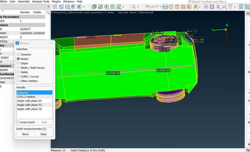
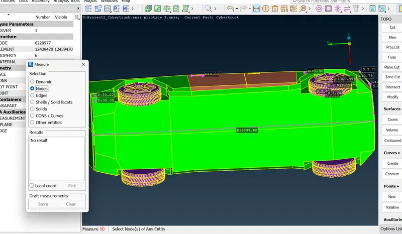 Measure the full length of the car that will taken as x distance,x=5738mm
To create front surface first measure length from mid point to front side distance + 4x
2525 + 4x= 25477mm
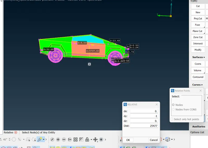
Rear surface;
3225 + 6X = 37653 mm
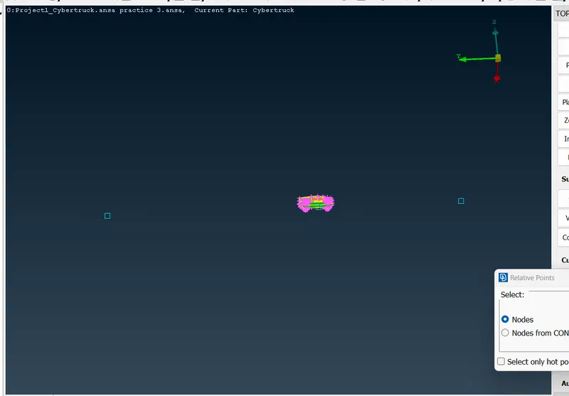
In the same way.
Side surface;
select front and back surface take x as distance ,
Relative > nodes> select node
first,dx=+1 direction distance = 5738 mm
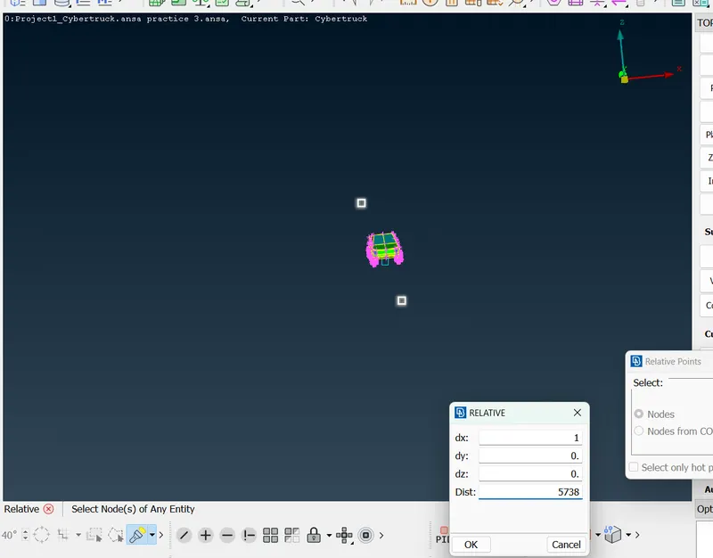
second ,dx=-1 direction distance =5738mm
for creating bottom surface ,first create curves on the points
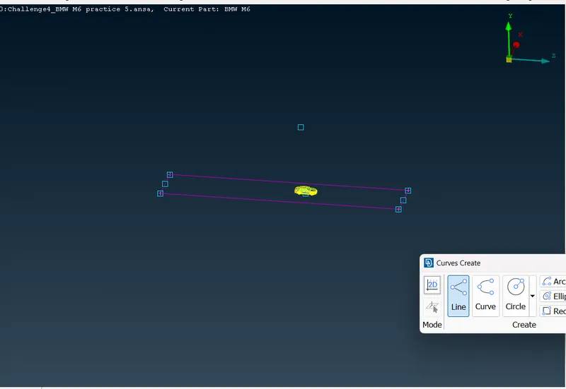
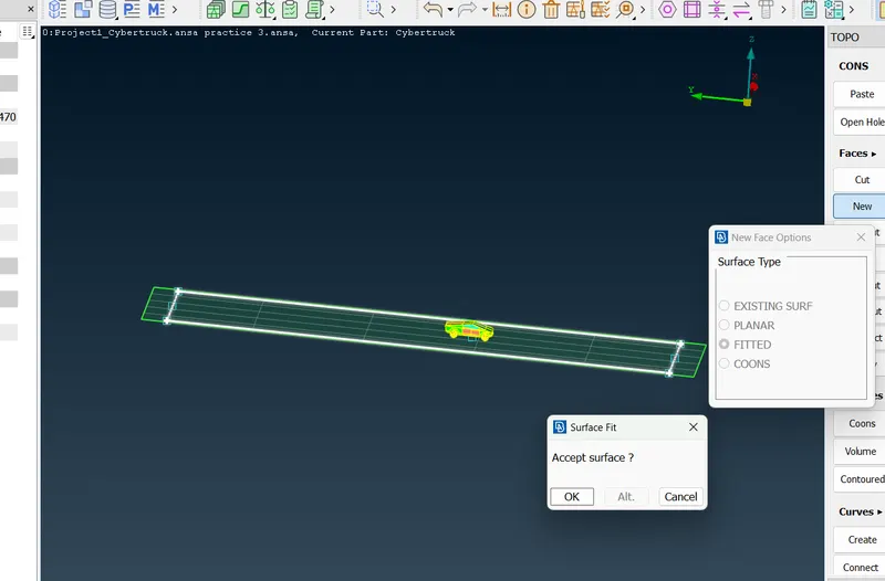
curves > create > select nodes
Faces > new > fitted > ok.
Top create top surface
measure the distance from bottom midpoint to top mid point = 1531mm
top surface distance = 1531 + 3x = 18745 mm.
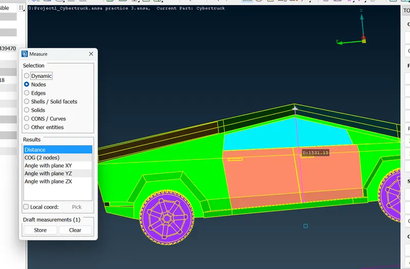
Faces > Offset > select the face > middle click > -1875 mm > ok.
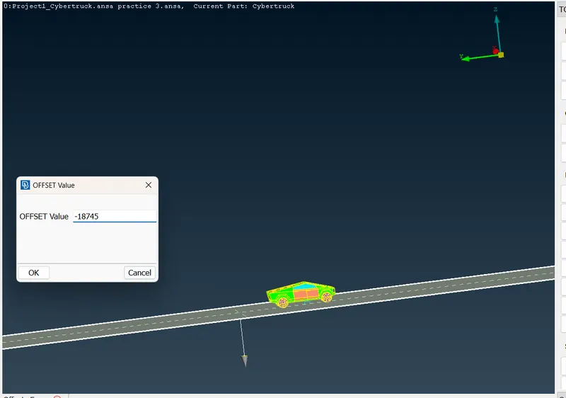
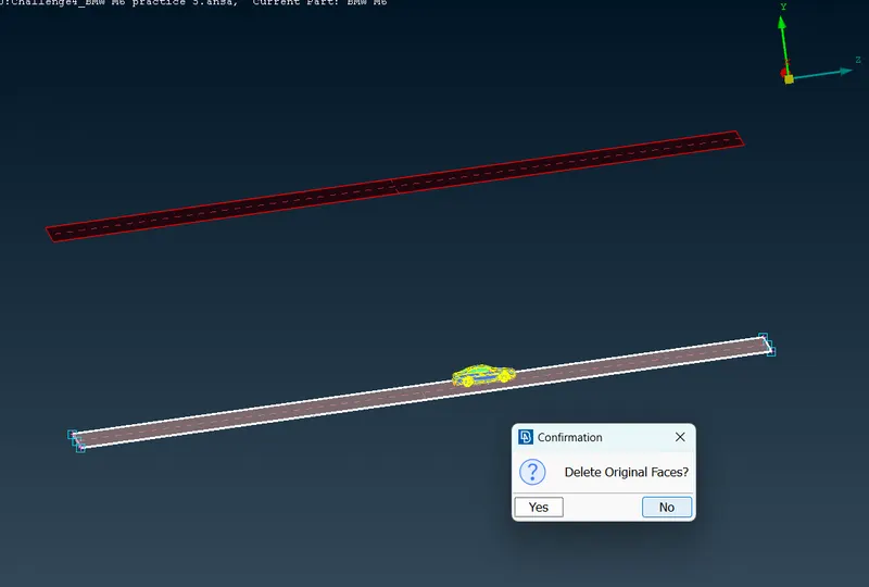
create side surfaces ,front & rear by faces> new > fitted & cons .
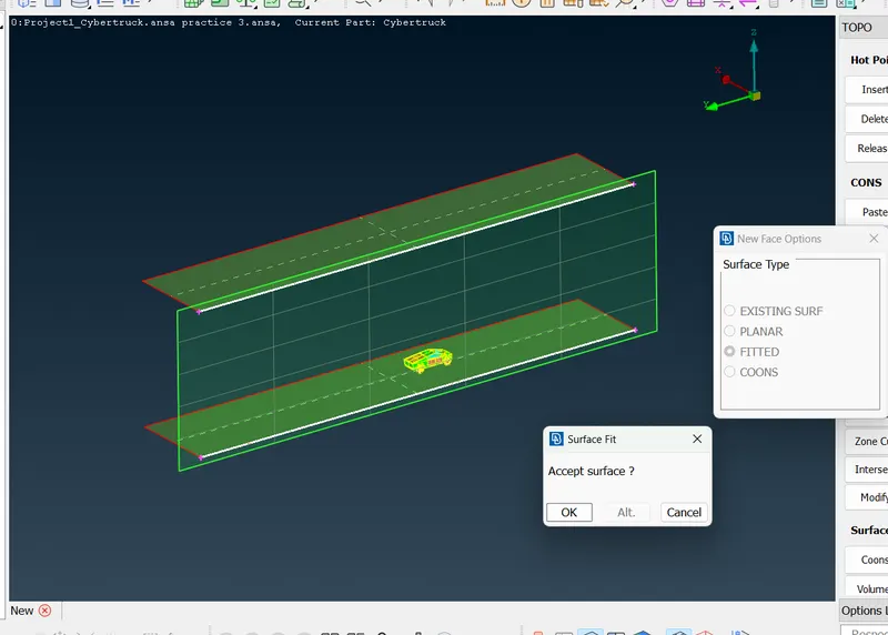
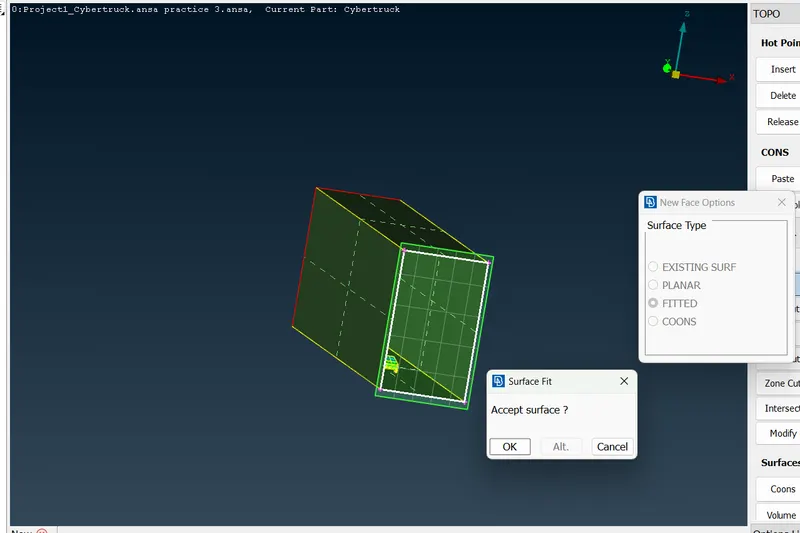
After that assign PID'S for surfaces.
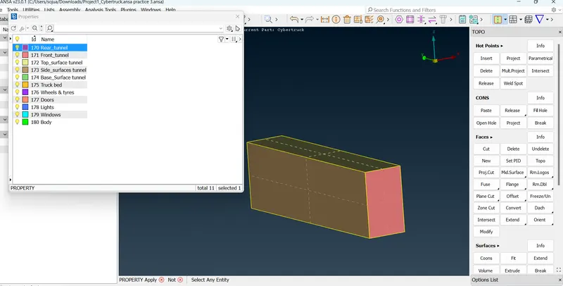
Step-6, Meshing the wind tunnel;
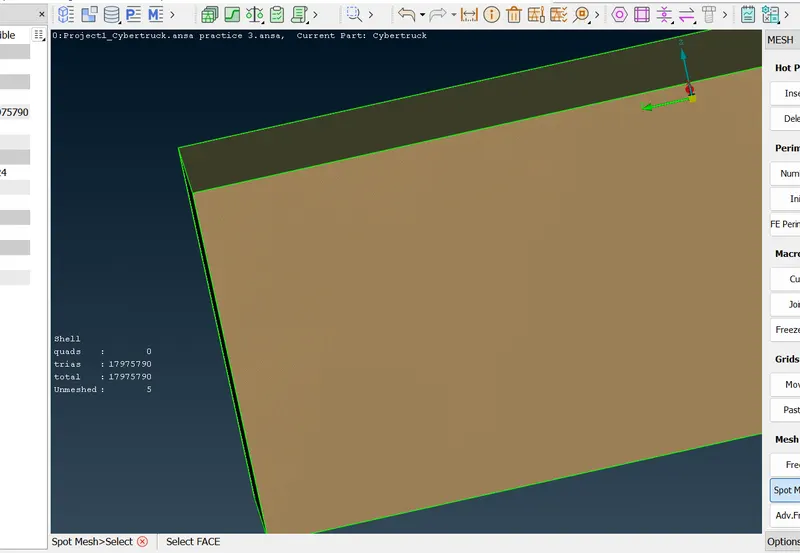
First do mesh on the the top & bottom surfaces.
we don't want much bother about quality criteria .
select top surface or isolate the top surface
Length > perimeter (100) >macros (100) > ok.
quality criteria > min: length 90mm > max : length 105mm > ok
Mesh parameters > target length(100mm) > min: length (90mm) > ok.
spot mesh > select > middle click.
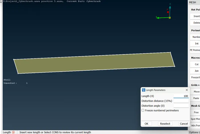
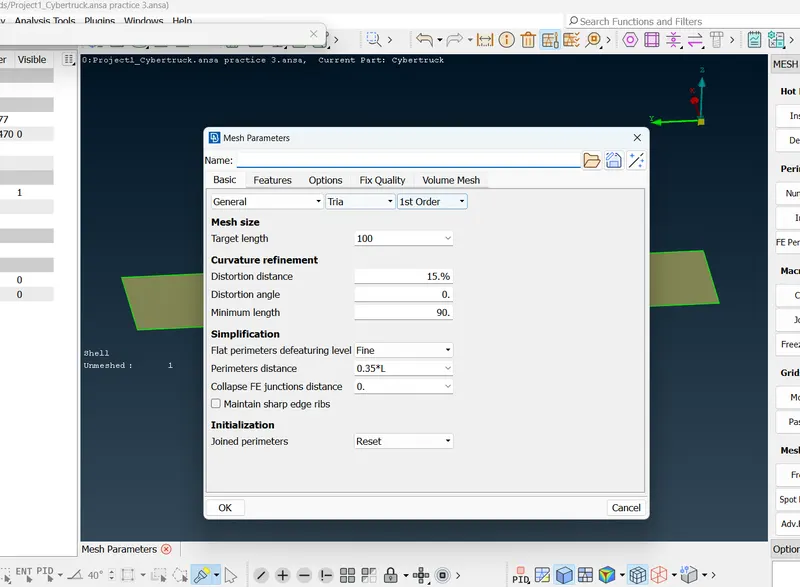
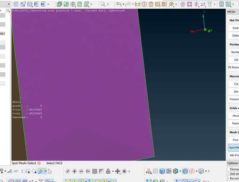
Isolate the bottom surface - length > perimeter(20mm) > macros (20mm) > ok.
quality criteria > min(15mm) > max(25mm) > ok
mesh parameter > target (20mm) > min(15mm) > ok.
spot mesh > select > middle click.
For side surfaces;
Perimeter > spacing > biasing (geometric ) > factor (1.1) >d start (20mm) > d limit (100).
select the side cons also look the direction,direction should be up .
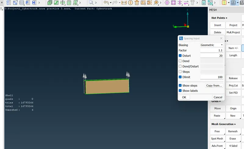
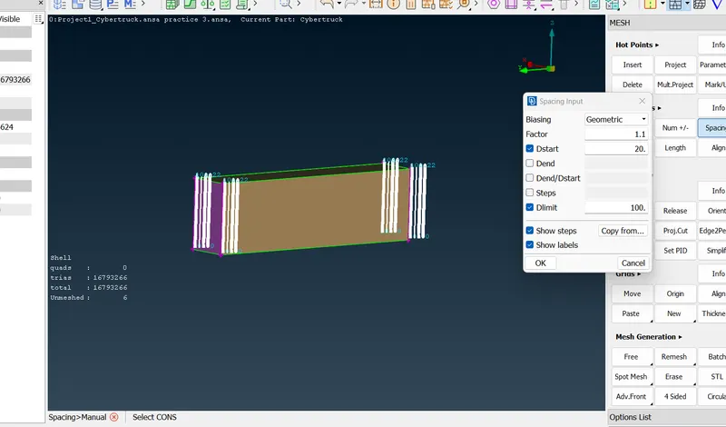
Here we can see the variation from smaller limit to larger limit.
before doing meshing keep the mesh parameter target length as average.
Mesh generation > spot mesh > select the faces > middle click.
Step-7 Volumetric mesh:
we only need the volume of the car and wind tunnel .
to define the volume;
Define > whole Db > ok
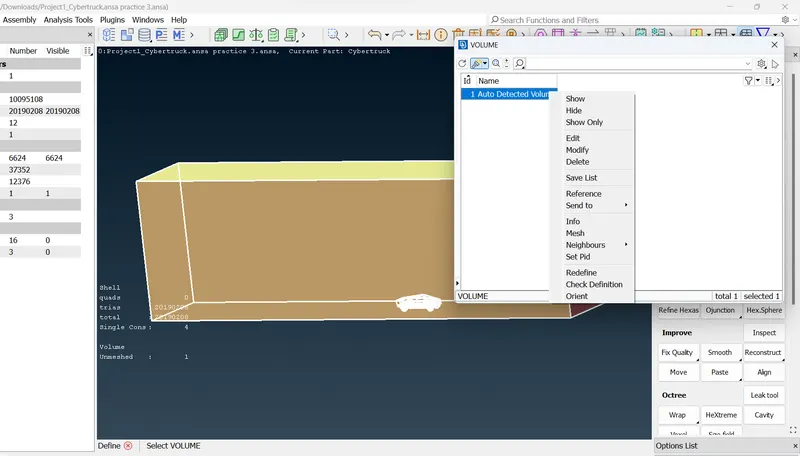
To do volumetric mesh
right click on defined volume > mesh.
Learning Outcomes ;
By doing this project we will come to know,
- To select the required volume for the volumetric mesh.
- To delete half entity of the car by using plane cut option.
- Smaller the mesh length finer the element and larger the mesh length coarser the element.
- Creating a point on plane without a surface using relative point option.
- Creating a surface at a required offset distance using offset option.
- Copy and transform entity using transform option.
Result;
We got the CFD meshing on a tesla cyber truck with given quality criteria.
Conclusions;
In order to do volumetric mesh on a component the component should only have one volume otherwise it will create different volume.
For wind tunnel test of the given tesla cybertruck the closer surfaces of wind tunnel which are closer to given component should have finer element and far away element are coarser elements.
https://drive.google.com/file/d/1pi2XkjuzTrC9ERgF5lDgqFdwIFwMdudv/view?usp=share_link