Week 3 Challenge : CFD meshing on Turbocharger
Aim:
- Check for geometrical problems in the provided model to create the proper volumes. PIDs should be created and assigned as per the video. Make a surface mesh using the provided target lengths in accordance with PIDs.
- Blade stage-1 = 1 mm
- Blade stage-2 = 1 mm
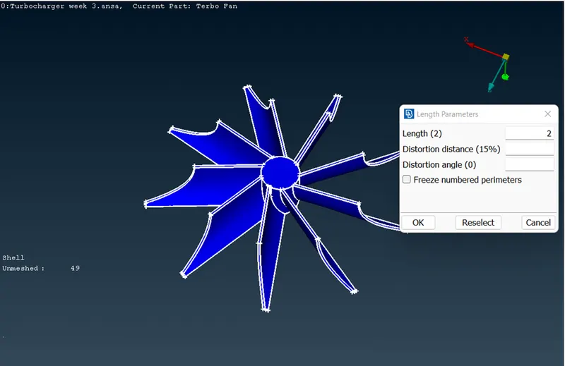
- Impeller = 2 mm
- Shaft rotor = 1 mm
- Turbo casing = 5 mm
- Compressor casing = 5 mm
- Inlet casing cover = 5 mm
- Perform Volumetric mesh for the required volumes as shown in the videos.
- Write a detailed report on your surface meshing & Volume meshing process.
Procedure:
Geometry clean up :
- Check for surface errors by selecting topo under faces in the topology option
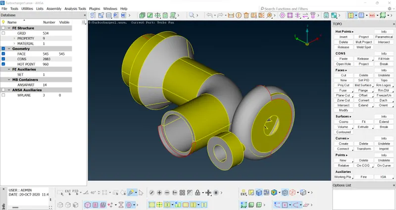
- delete the overlapping surface
- delete rest of the surface by selecting not and then selecting the main surface and hiding it to show the overlapping surfaces
- delete surface irregularities
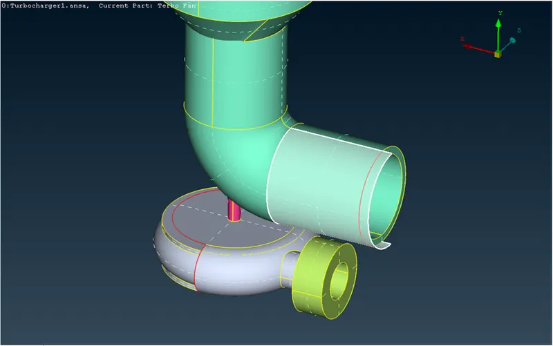
- create new surface that were deleted while deleting extra surface
- fix the intersecting faces by using intersect option then delete the planes to solve tri cons
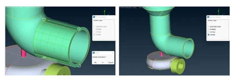
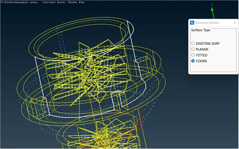
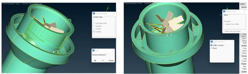
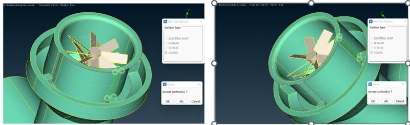
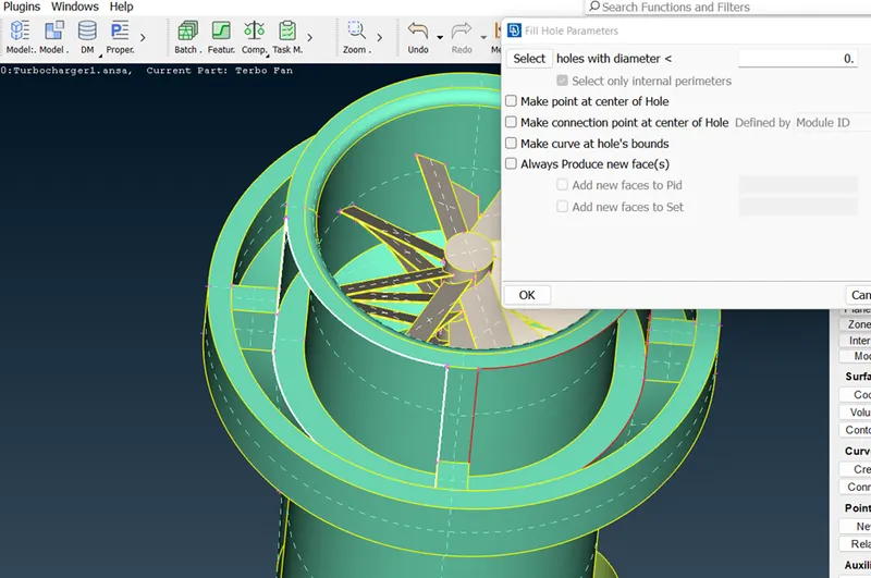
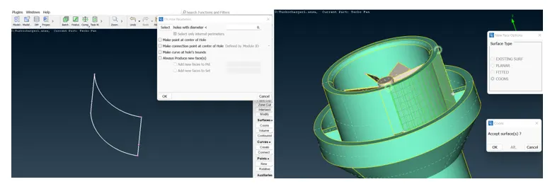
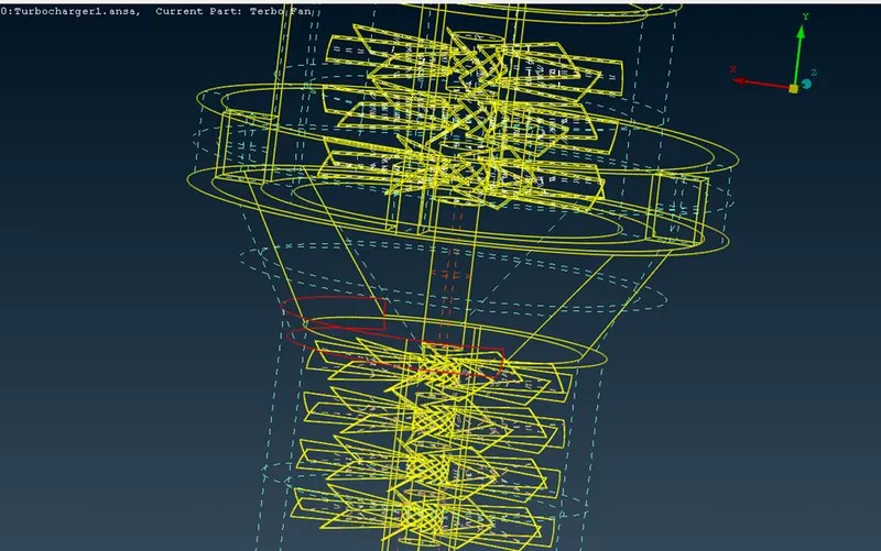
- release the tri cons if extra surfaces have been deleted
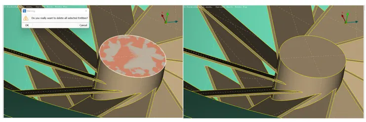
- cut this area and delete the surface to rectify tri cons
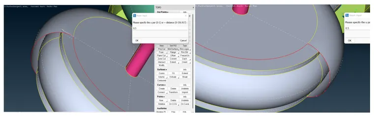
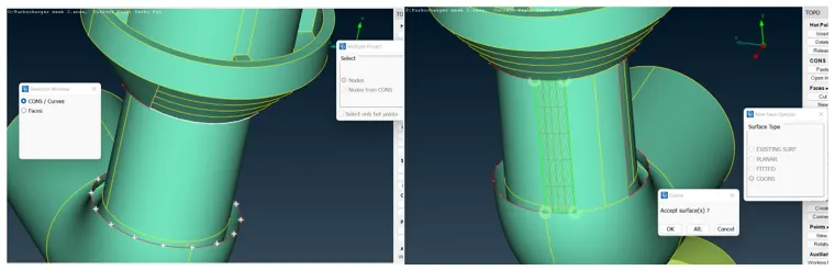
- create various hot points to generate this complex curved surface
- now create new surfaces
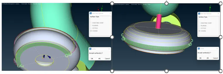
- new surface created

- check for geometry for single cons
- errors detected
- single cons were rectified into triple cons by topo feature
- this tri con can be ignored as this is a shared edge by two entities
- rectify triple cons on the shaft
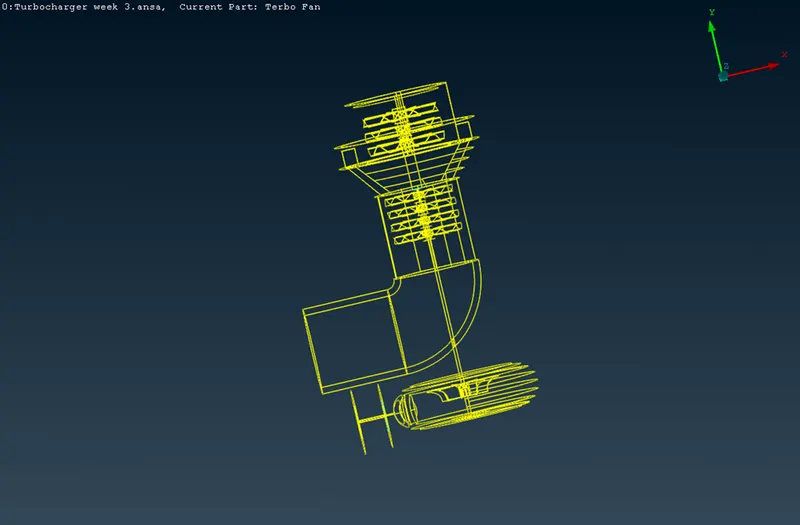
- once done with all the rectification check for single and triple cons by using topo
- no single and unnecessary tri cons
Assigning the PID :
- rename the PIDs according to the respective parts
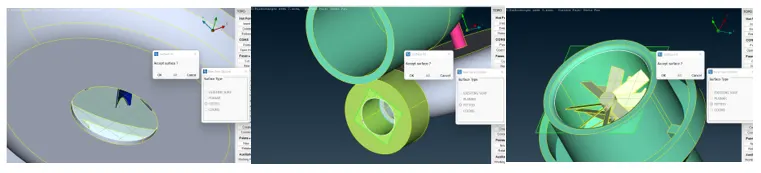
- create PIDs for filled holes
- all final PIDs

- check for any single cons before moving to volumetric meshing
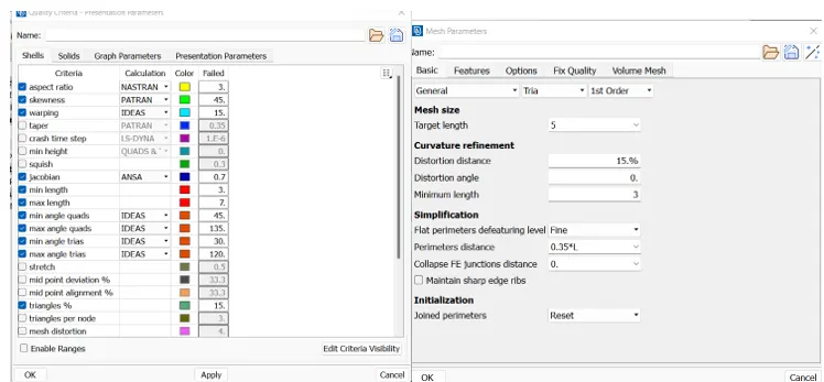
- set the mesh parameters accordingly
- set quality parameters accordingly
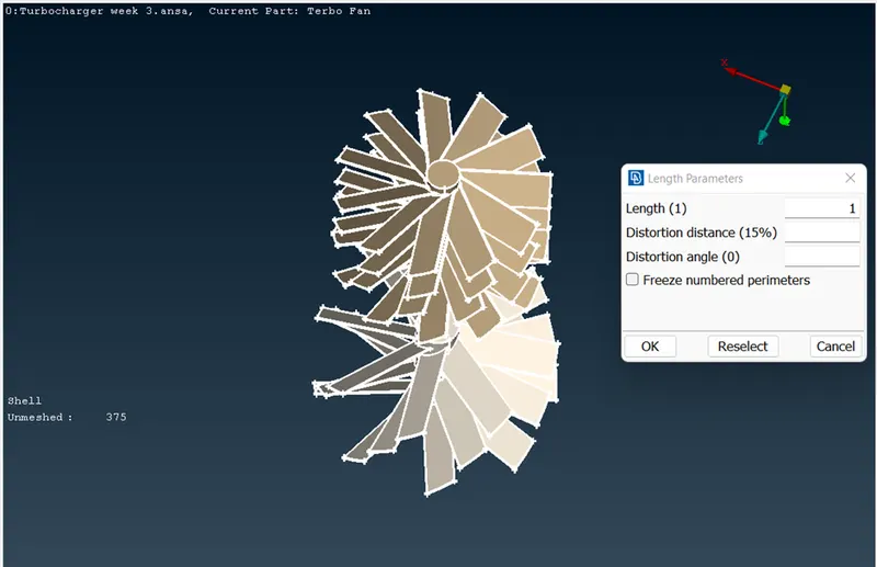
- set the perimeter and macros accordingly
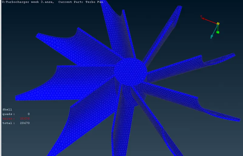
- spot mesh the component
- for impeller and shaft junction meshing set the para and macros only for impeller
- general mesh setting for impeller
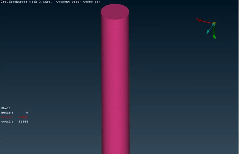
- general settings for shaft
- quality settings for shaft , max length should match the element size of impeller
- repeat the same process while keeping element lenght as 5mm for peri and macro
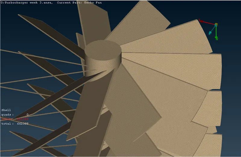
- check mesh around shaft and casing junction region, as well as shaft and impeller region
- cut the surface to create an area of varying mesh size
- check presence of any error in by checking unmeshed surfaces, here there are none
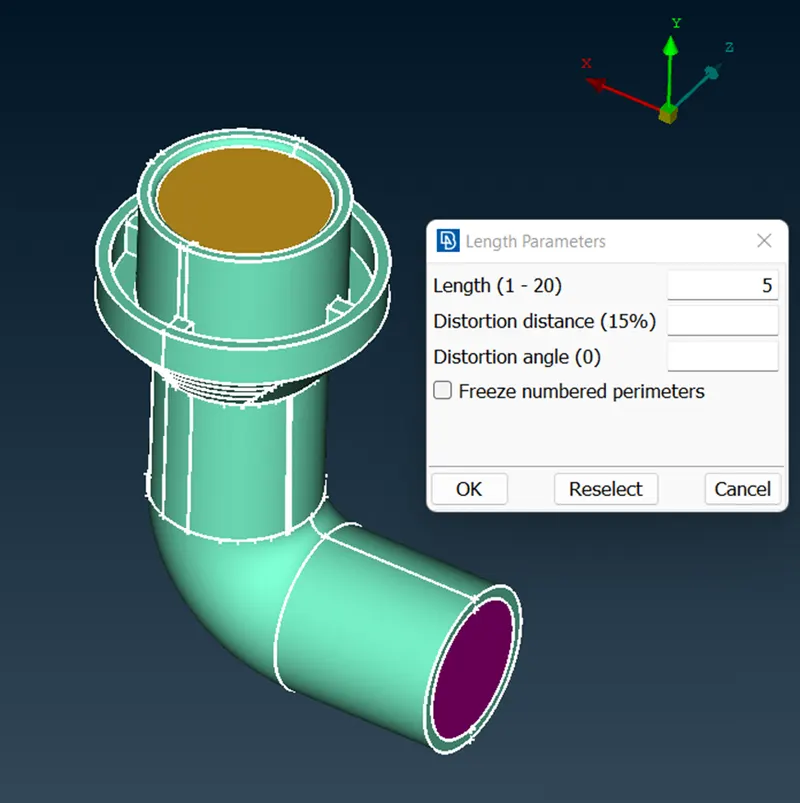
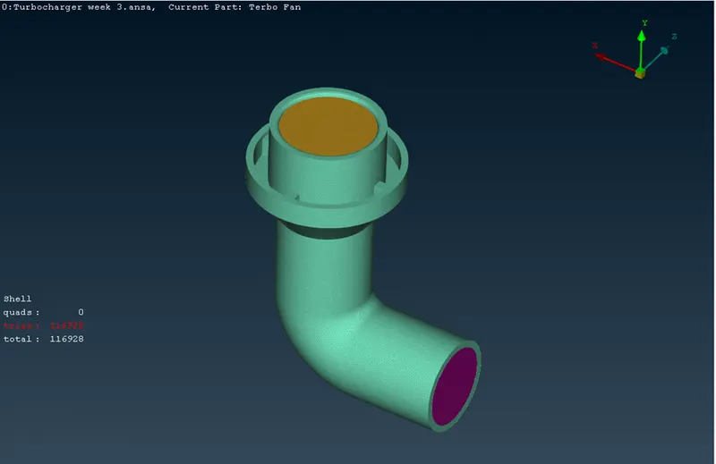
- fill the inlet and out let holes for CFD meshing
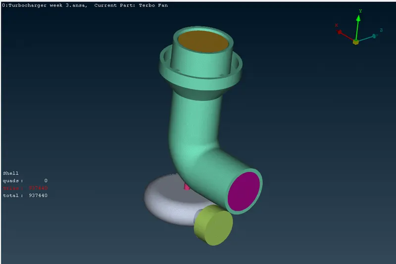
Volume meshing :
- start volumetric mesh by using define feature
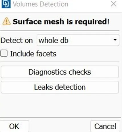
- then you'll get a list of undefined volumes
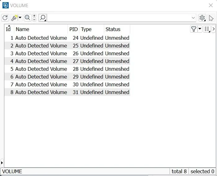
- delete unnecessary volumes
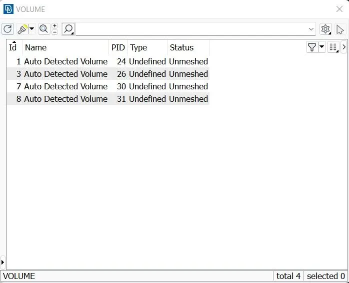
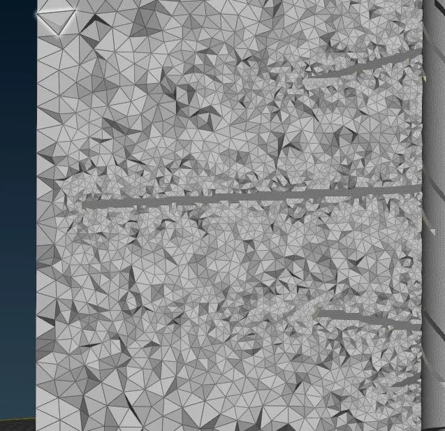
- remesh the remaining volume using tetra cfd
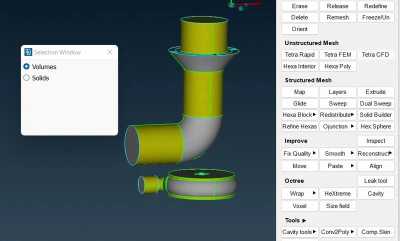
- make sure there are no unmeshed volumes
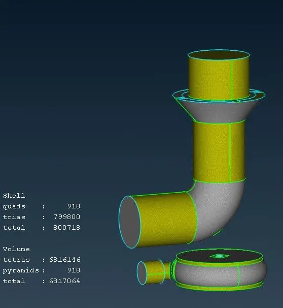
- check for mesh by using not option with entity selection and box select the entities to be removed
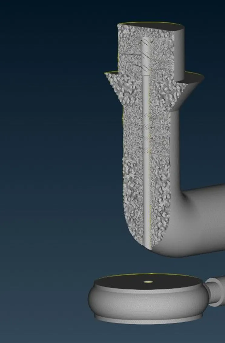
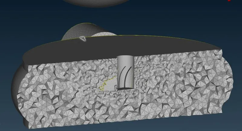
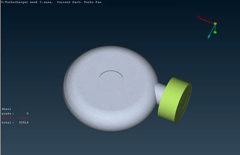
- the reason for variation in mesh lenght, is due to difference in ele size of deiierent elements, software tries to combine diff element lenght by variation in mesh size
Results and observation:
- Various tools from the Topo deck were used to complete the geometric cleanup.
- Deleted the overlap surfaces, or IE, as they were superfluous.
- The errors of intersection and penetration were eliminated.
- Unique surface mesh creation for a predetermined target length.
- A volume mesh was only made and identified for the area where the fluid is flowing.
- It built the volumetric mesh.