Week 3 Challenge : CFD meshing on Turbocharger
CFD Meshing on Turbocharger
AIM :To check for the geometrical errors to make appropriate volumes. Create and assign PIDs . Perform surface mesh with the given target lengths as per PIDs.
Procedure: Check for the geometrical errors
Create and assign PIDs
surface mesh with the given target lengths as per PIDs
volumetric meshing
Learning outcomes:
- PID creation and PID assignment,
- Different selection techniques and visibility tools,
- Advanced Topology cleanup
- Advnaced tools used in Surface mesh
Methadology
Step1: Cheak for geometrical and intersection errors
By observing the below model here we can see glicthes , which means there is overlapping exist to remove
we can do with many methods one of the method is with pid method turn of the flas bulbs in the window
identifing the unrequired parts and deleting.
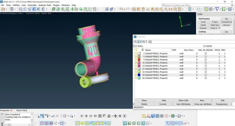
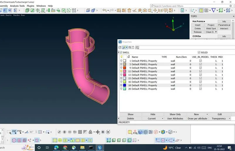
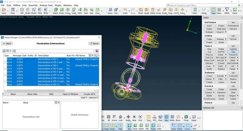
cheaking for errors
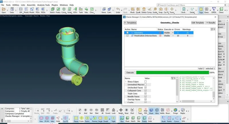
In the above window we can observe single cons and intersection errors
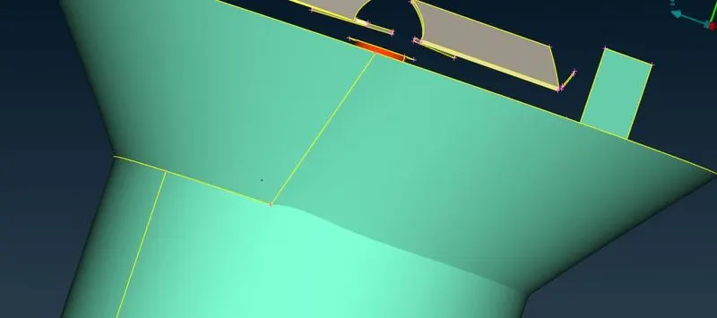
for above picture now certain boundry will be cleaned up with intersect option and deletion of unrequired part
creating proper boundry
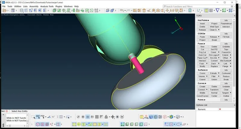
in turbo caseing there is intersection error , we can see glithcing now to remove that we can go to cons projecting
projecting the cons on shaft we can cut shat faces and remove the error.
Removeing triple cons where because this makes more volumes , so to make single volume
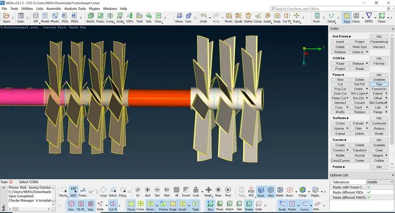
in the below window ther is single cons and to fill the face we use transform option, by three points we can create
here we are oposite face of existing face
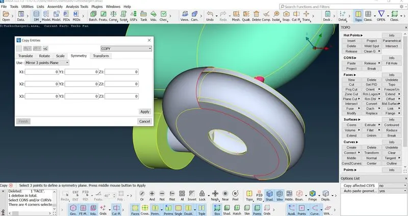
After cleaning up going for cheking for error
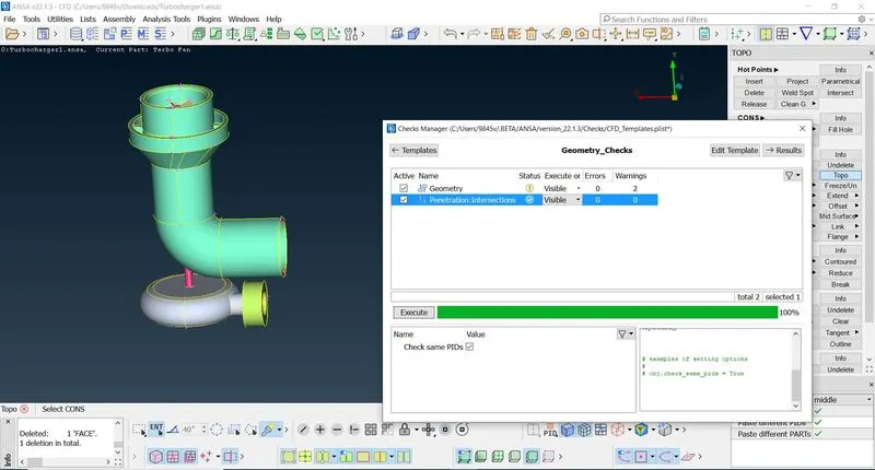
Closeing all the inlets and outlets
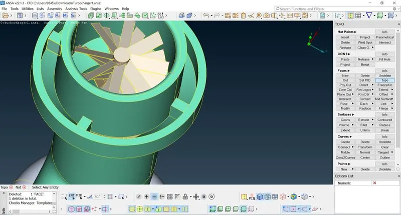
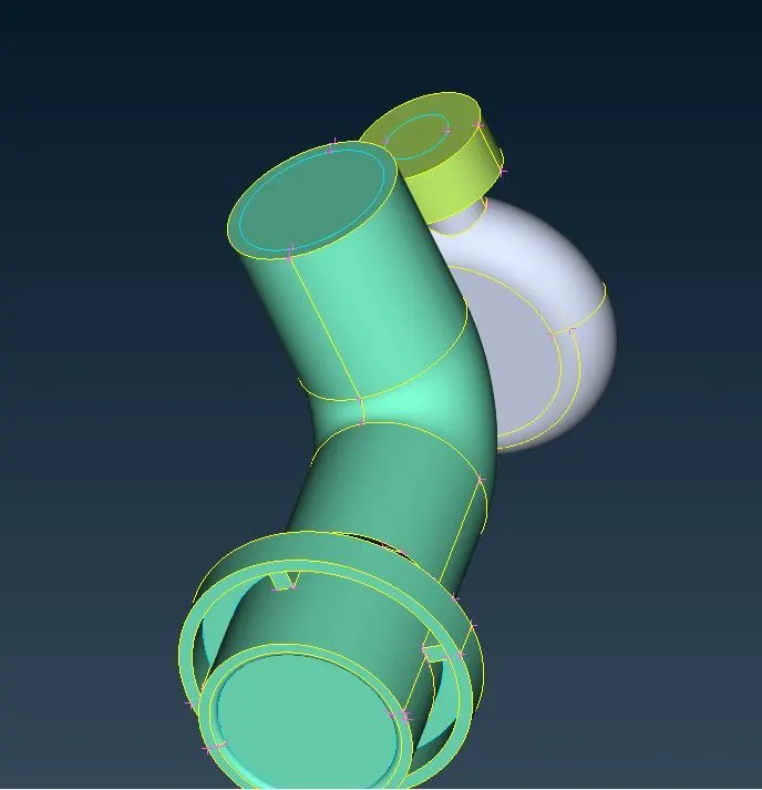
But we can not avoid some nessery tripple cons shown below
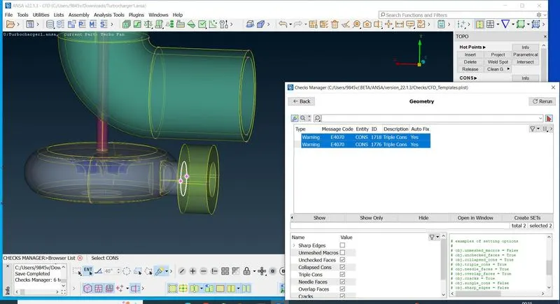
After topo cleanup
Step 2: PID application diffrent parts
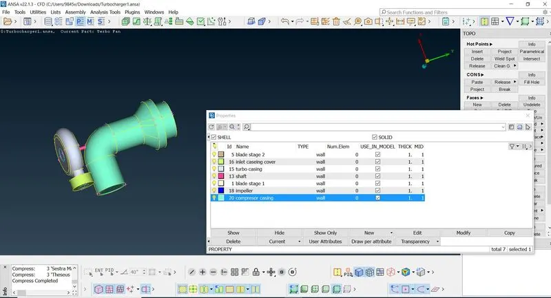
here there are 7 parts they are they are turbo caseing , comressor caseing ,inlet caseing coverand blade stage 1
inlet blade stage 2, impelleror and shaft
Step 3: Meshing all the parts with given target lenghts
- Blade stage-1 = 1 mm
- Blade stage-2 = 1 mm
- Impeller = 2 mm
- Shaft rotor = 1 mm
- Turbo casing = 5 mm
- Compressor casing = 5 mm
- Inlet casing cover = 5 mm
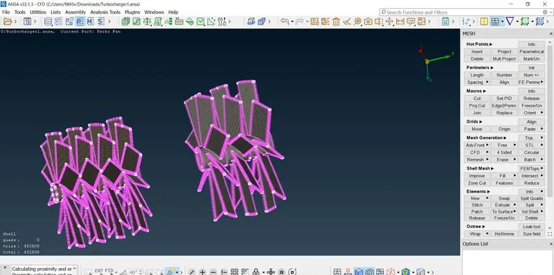
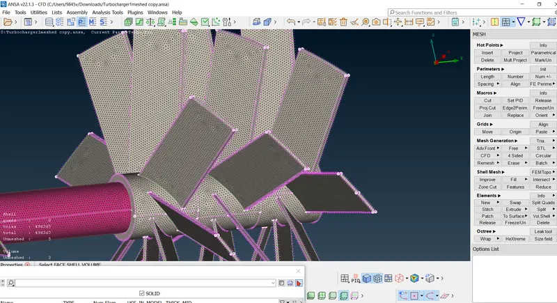
Impellor
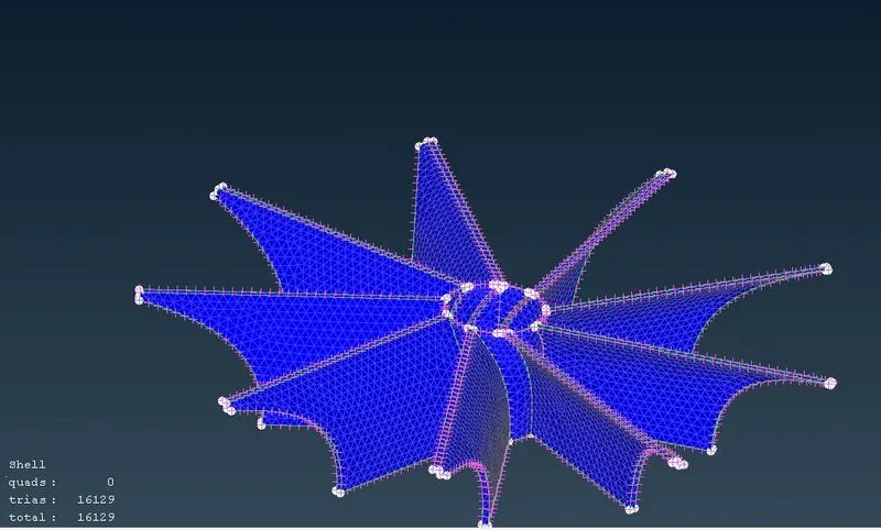
How to mesh this parts - here we select mesh parameters and giveing target lenghts , maximum and minimum target lenghts
maximum target length any thing above target lenght and minimum target lenght is anything below target lenght and giving spaceing and auto cpd giving perimeters and and macros and going to mesh generation section and select cfd visible .
here Frezing is important to maintain created mesh as it is , otherwise it will creat fault
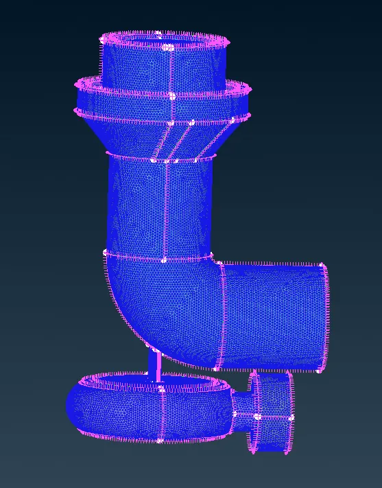
unfreezing
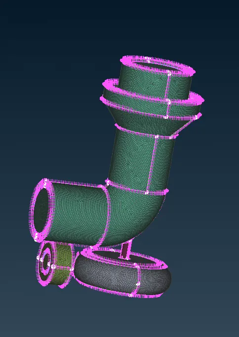
Fully meshed model is ready
Step 4: volumetric meshing
Before going to v.meshing we have to define volume here, we are here considering only internal volumes where only flow is going to takes places
Defining volumes
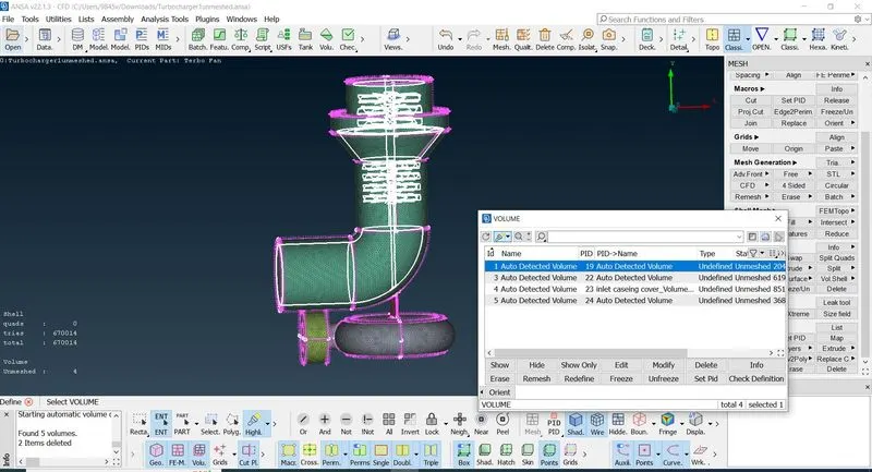
above window will open when we go to volume section select define volume and click ok all the volumes will be showed
deleting external volumes , keeping the internal volumes
V.meshing
in the above volume window type of mesh not selected
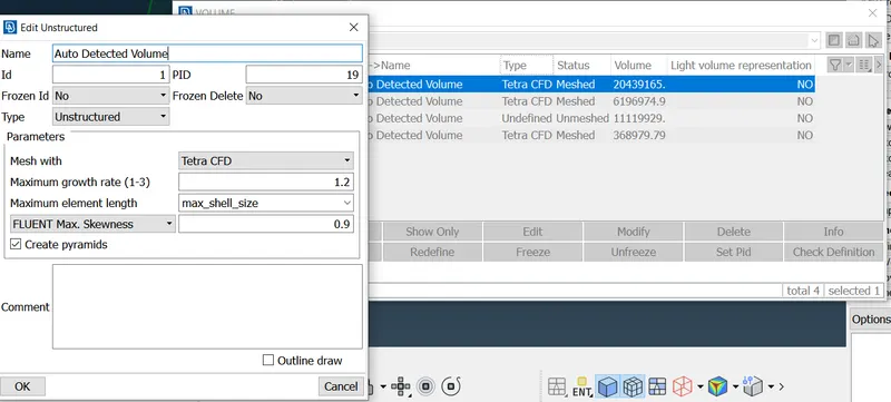
Remeshing the thouse volumes by right click
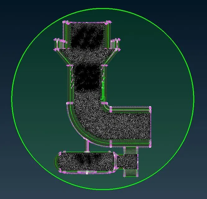
To chek volumetric meshing , sectional cut is made
Step 5: cut plane
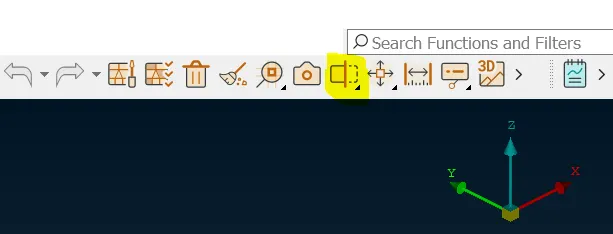
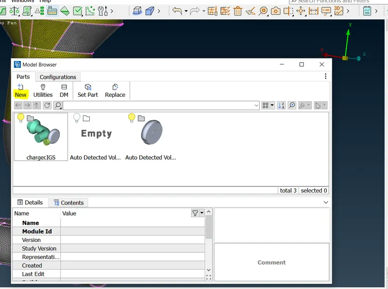
selecting cut plane option above highlighted ,select new, and plane in which it is to be cutted is xy for this select point on the model and then select new part in the window opened
and final sectional part is ready
Result:volumetric meshing for internal flow analysis meshing is done
Conclusion: We can conclude that surface meshing is pre requisite for volumetric meshing and we need to decide the volumes manualy is it external or internal volume