Week 2 Challenge : Surface meshing on a Pressure valve
Surface meshing on a Pressure valve
Aim : For the given model, check for the geometrical errors and perform Topology cleanup accordingly, and creat mesh for 3 diffrent target lenghts.
Prodecedure :Check for the geometrical errors
Topology cleanup
Set up mesh
Learning outcomes
- PID creation and PID assignment,
- Different selection techniques and visibility tools,
- Basic Topology cleanup
- Basic tools used in Surface mesh
Methodology
STEP 1: Cheak for Geometrical Errors
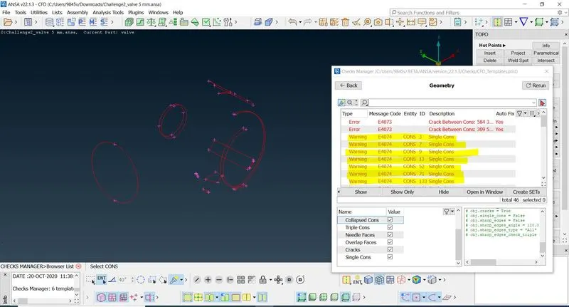
Cheaks manager is important to cheaks diffrent types of error present in the geometry for Meshing
for given model we we are going to cheak the geometry and intersection error,
for given model intersection error were present in coloum and spring
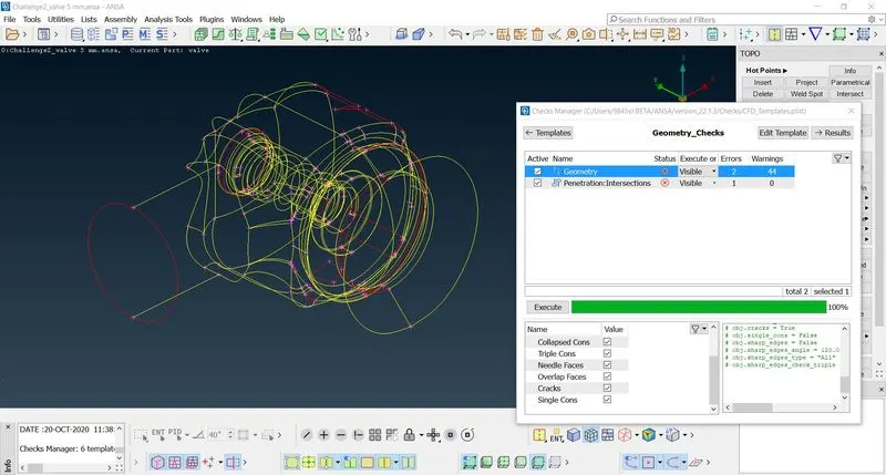
Image shows the Cheaks manger window and wirefreme mode of model
Step 2:Fixing the the error
In faces options Selecting the New option will gives us diffrent methods filling the wholes
In them every option wont works fitts perfectly for everything
selecting best surface left to us
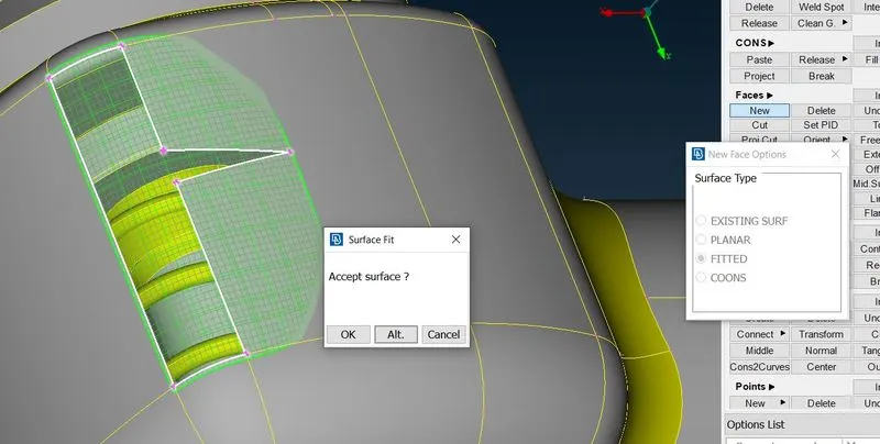
fitted both alternatives do not match
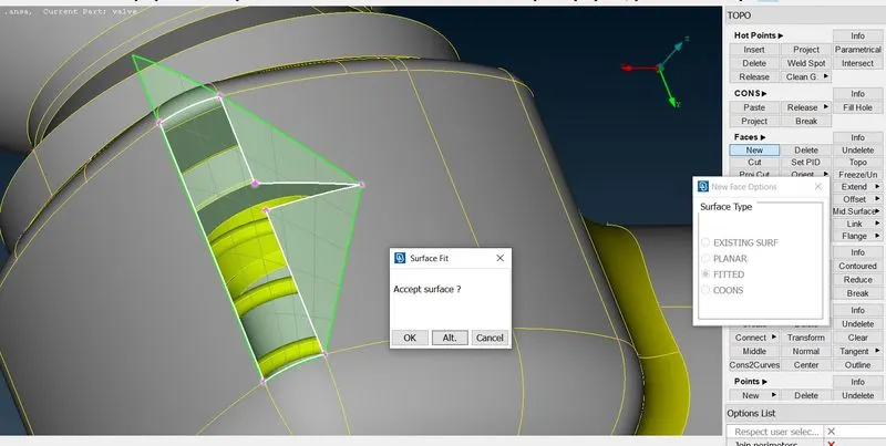
Fitted alternative also not matching
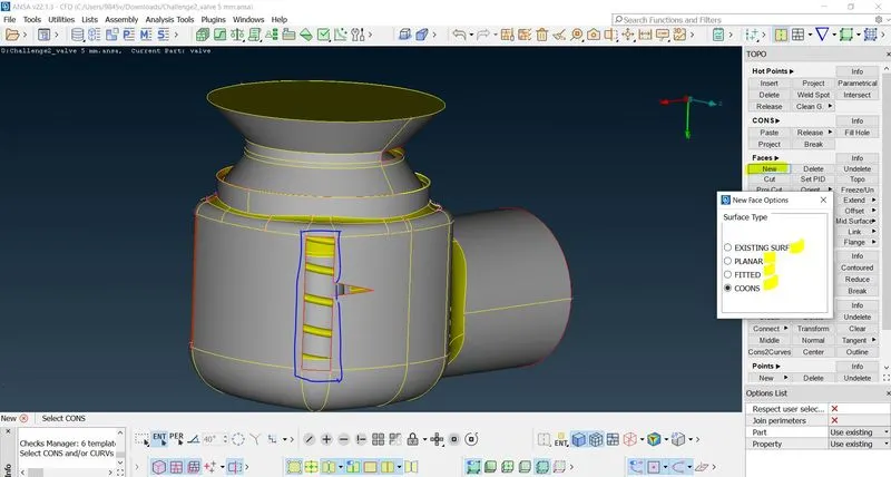
ENT mode with conts works better for this
Like wise fill hole option in cones works neatly like there were no pacthes before gives no cross hatchs
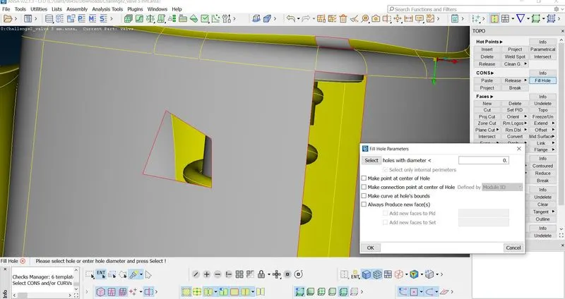
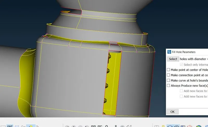
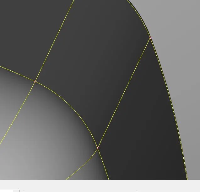
Above picture shows the filled suface with fill hole option
Step 3:Cheaking for Error With cheaks manager
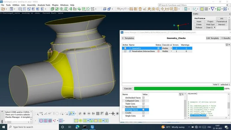
still the intersection error is exists
Step 4: Removeing Intersected Errors in Coloum
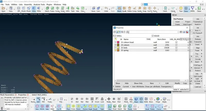
Assigning Pid is important Part here
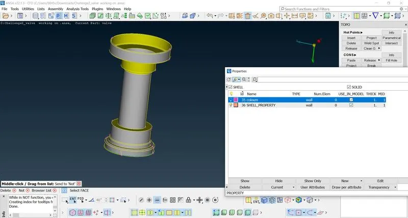
Pid assigned to coloum part ,we confirm that with is bulb is glowing.
If bulb is not glowing or off then it is not assigned to any part or the Part assigned with that Pid is not Visible.
After assinging Pid to all the Parts it becomes Easy to work on required Parts
To remove intersected part we have to Select Intersect option in Faces
After that selecting parts between where intersection exists
computer shows and asks for which parts to be deleted and keep as below
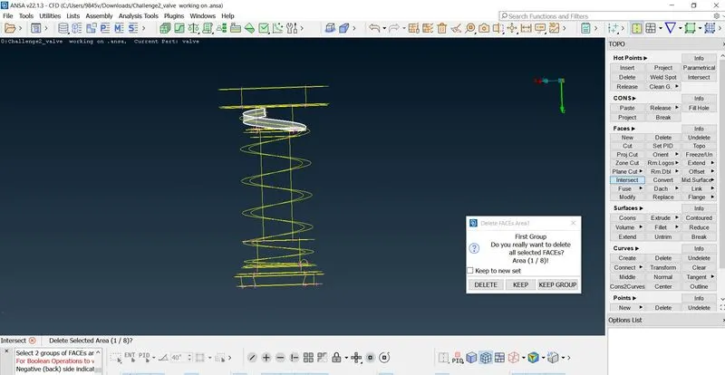
Step5: Cheak for intersection error for confirmation
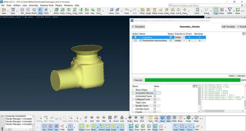
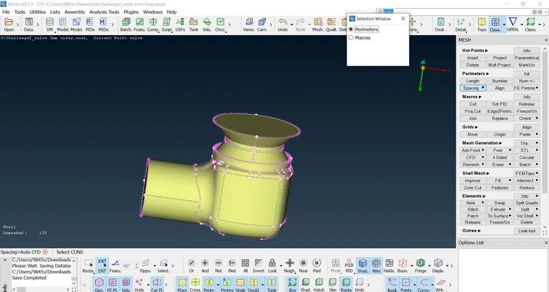
Meshing (without spaceing auto CFD)
Sample meshing with CFD mesh with target lenght 5mm
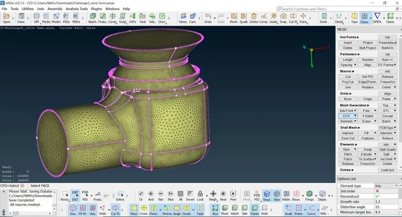
Explanation : without spacing with auto cfd we can see that mesh is growing from cons which is not Uniform
Unstructered mesh
Meshing (with auto CFD in spaceing)
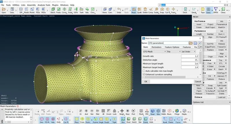
CASE 1:5mm target lenght ,tria mesh ,CFD meshing
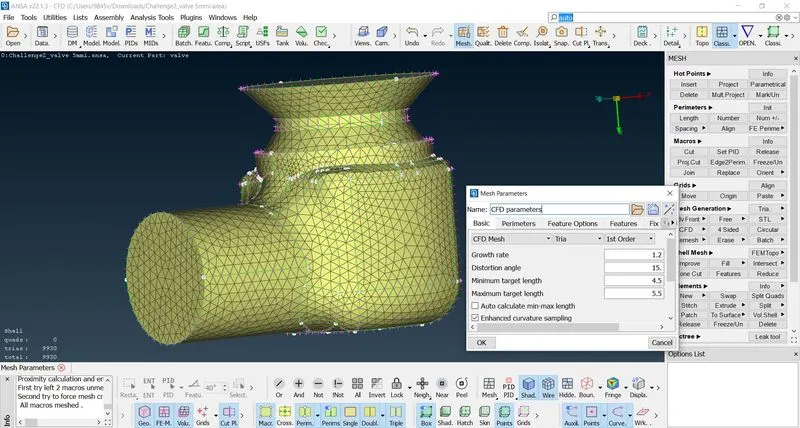
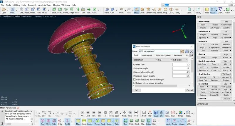
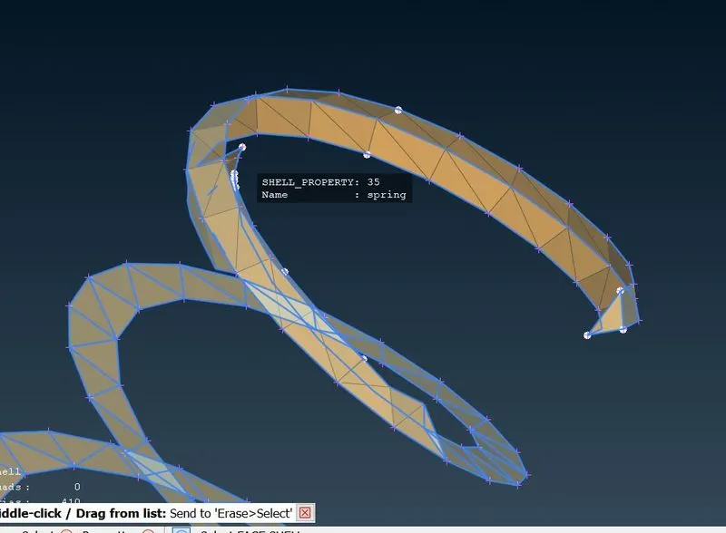
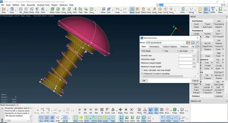
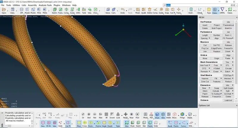
from this case we understand that mesh lenght is not approrpriate for the model or for the spring
where is looseing its shape it had became flat
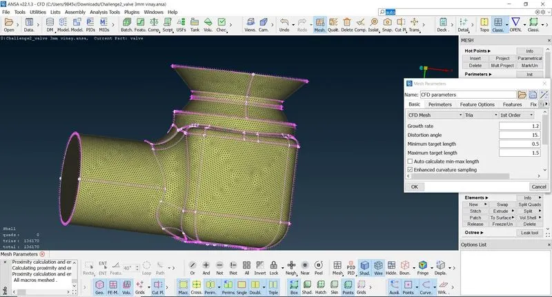
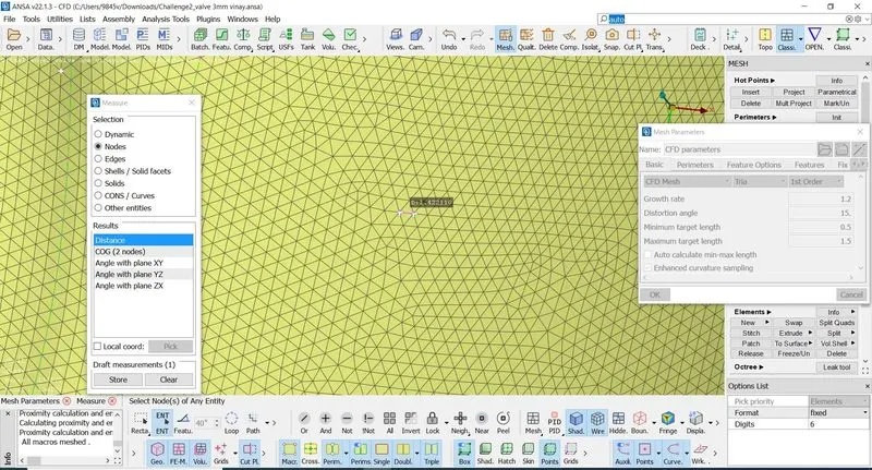
CASE 2: 3mm target lenght ,tria mesh
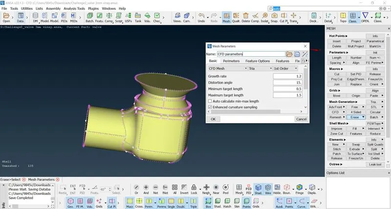
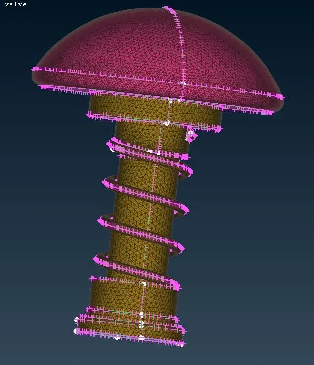
CASE 3:1mm mesh length , Tria mesh
Result:
By observing the 5mm target lenght is very larger in some of corners and spring , where cuves and sharp edges deformed not fitting this so 5mm case is't good for whole parts
Coming to 3mm target lenght even though it is better than 5mm target lenght still some improvement is need
1mm target length fits better as observing it is capturing all the elements in model
Conclusion :
from the above 3 cases we can conclude that as the target lenght decreses it gets better but we have approch with suitable mesh and Target length