Week 3 Challenge : CFD meshing on Turbocharger
AIM:
- To create and assign PIDs of the Turbocharger.
- To reduce the geometrical error to make appropriate volumes.
GIVEN:
- Blade stage-1 = 1 mm
- Blade stage-2 = 1 mm
- Impeller = 2 mm
- Shaft rotor = 1 mm
- Turbo casing = 5 mm
- Compressor casing = 5 mm
- Inlet casing cover = 5 mm
OBJECTIVE:
- Perform surface mesh with the given target lengths as per PIDs.
- Perform Volumetric mesh for the required volumes as shown in the videos.
- Write a detailed report on your surface meshing & Volume meshing process.
PROCEDURE:
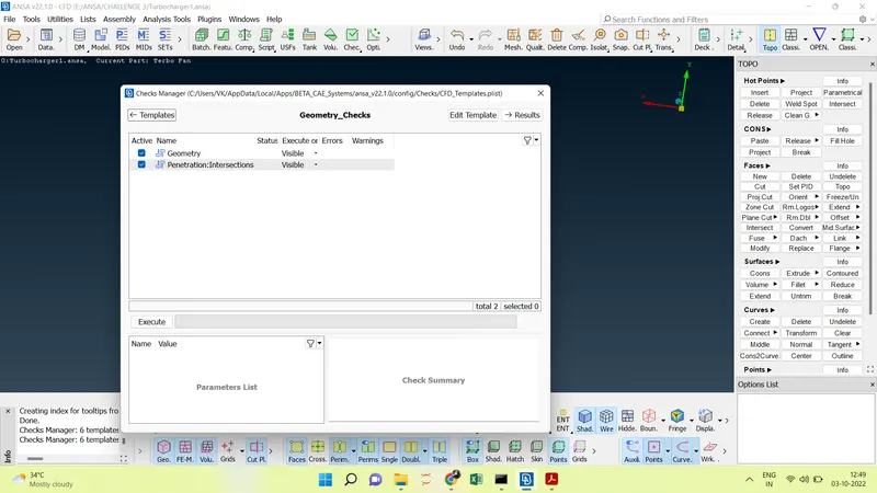
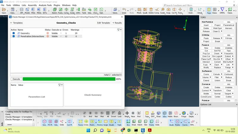
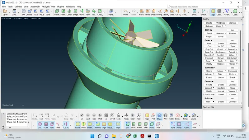
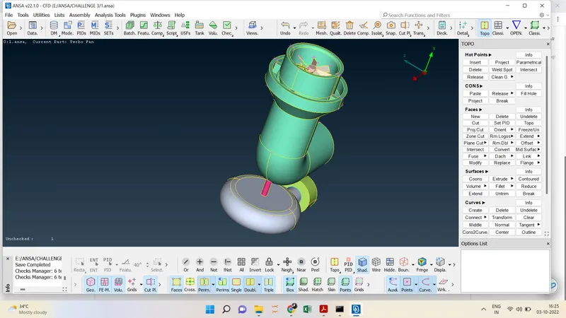
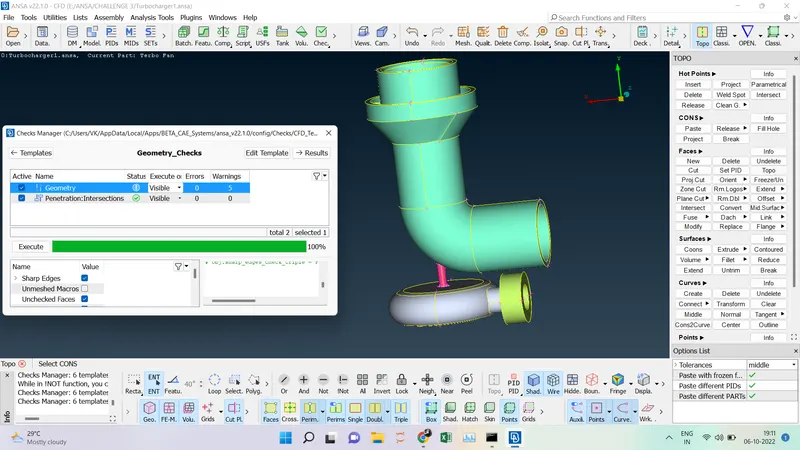
- Before Performing any changes in the Model we have to check the Geometry error and Intersection errors.
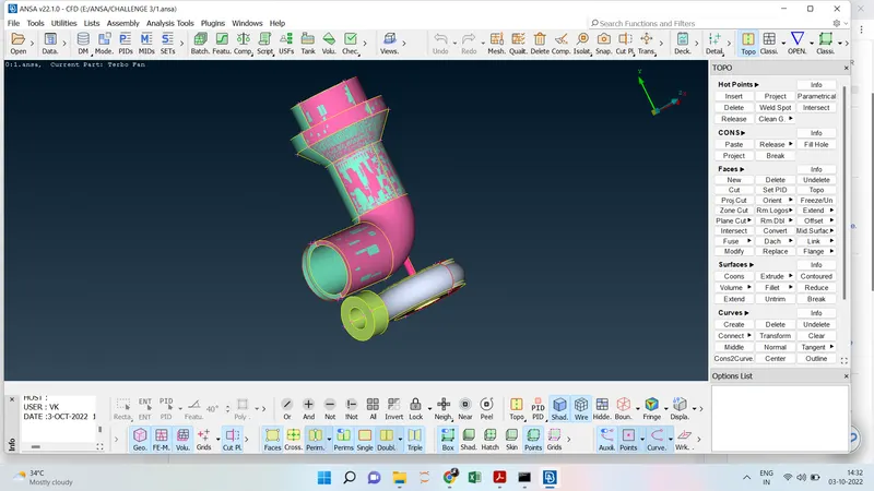
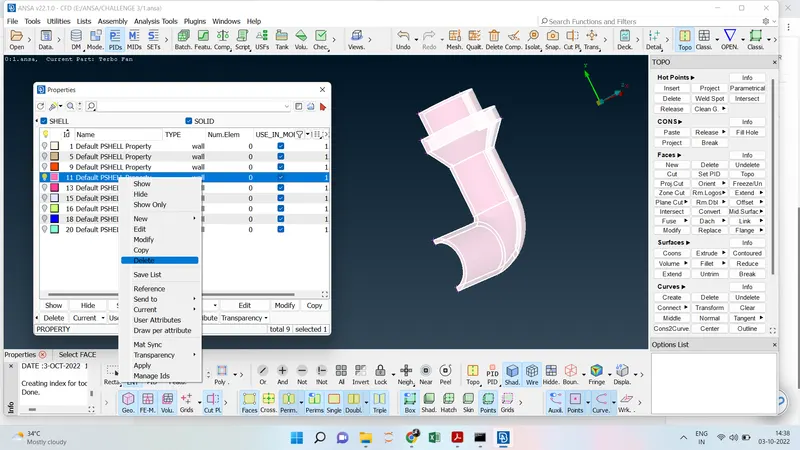
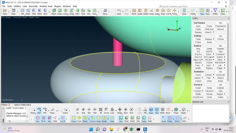
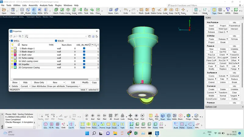
- To assign the PIDs for that we have to change the mode from ENT ---> PID mode there it is visible that the pink section is overlapping with the green section for that we have to check to select the one-by-one PID which is not required we have to delete that section.
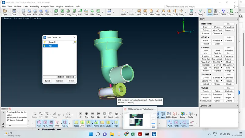
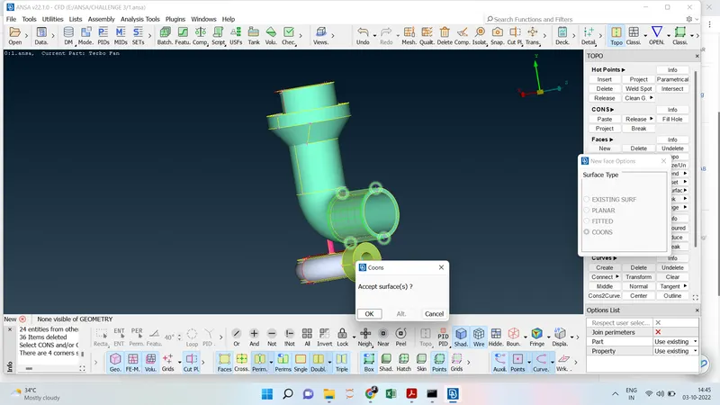
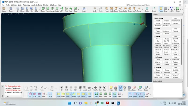
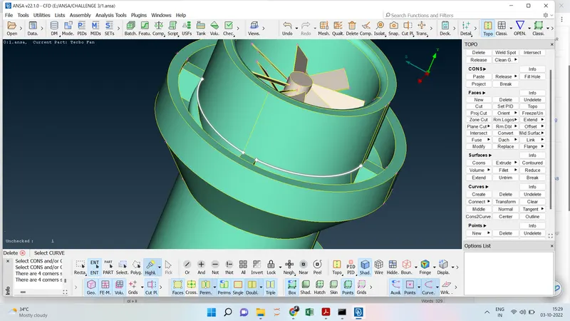
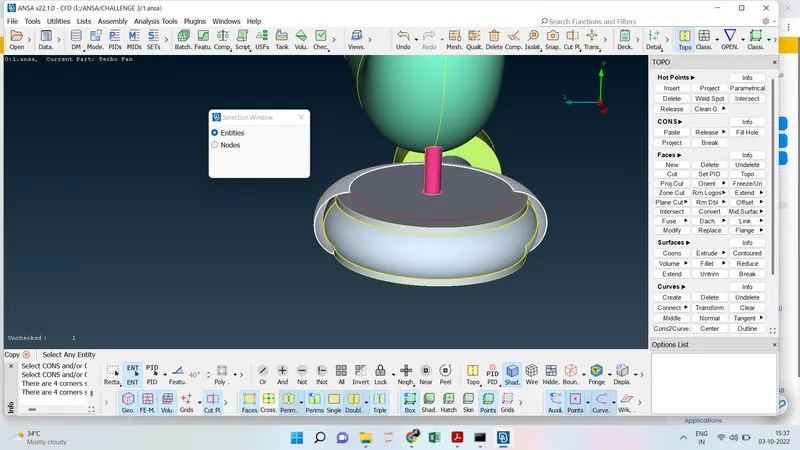
- Now we are going to reduce the single Cons by deleting the unwanted surface and creating the surface which is incomplete.
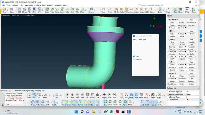
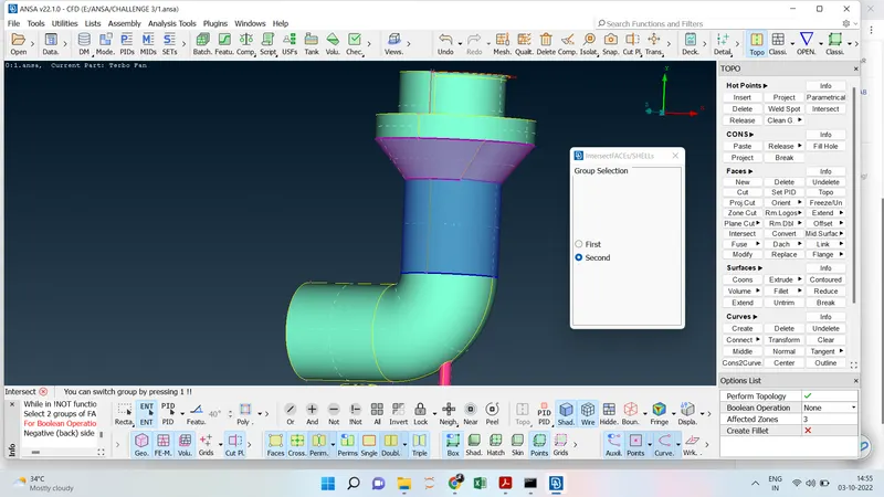
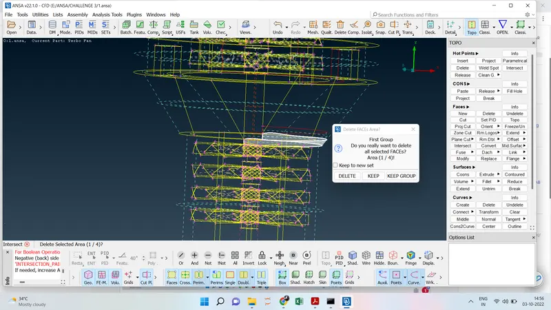
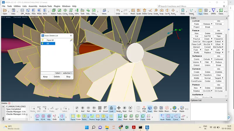
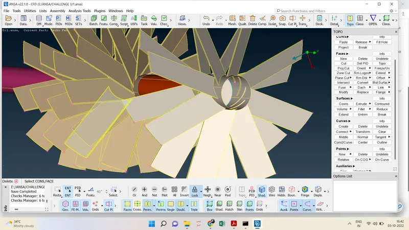
- There are no double cons not available at the two intersections due to the improper geometry for that going for Faces ----> Intersect ----> we have select the first surface and select the second surface and then center click then a dialog box will the surface will show one-by-one if the surface is required we have click keep if any section it's not required we have click delete.
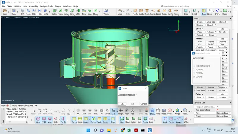
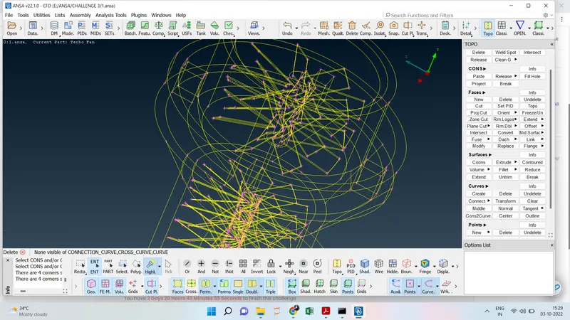
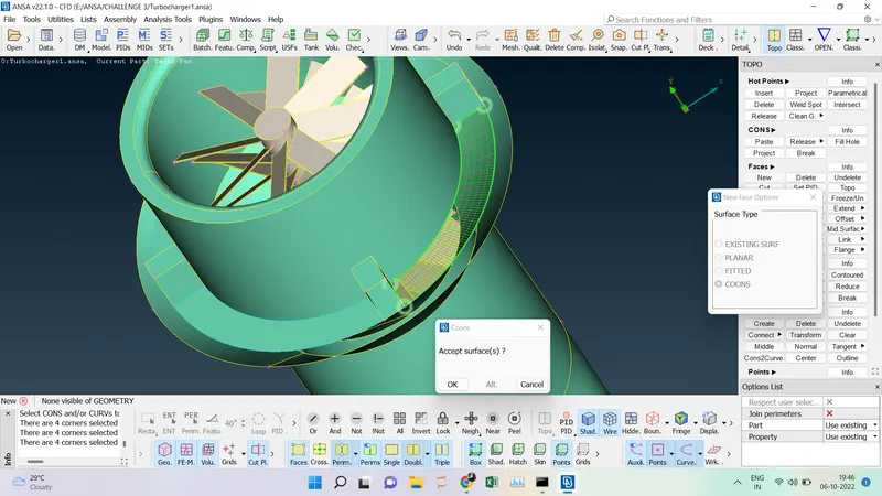
- To create the missing surface for which we are using the Curves ----> Transform ----> Select the Curve and middle click ----> Select the hot points. To create the surface Cons ----> Select the curves ----> Middle Click. At the bottom we can go for the same Cons ---> Loop then the surface will be created. Then created curves should delete by clicking the Curves ----> Delete ---> Select the curves to be deleted.
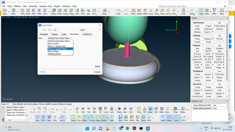
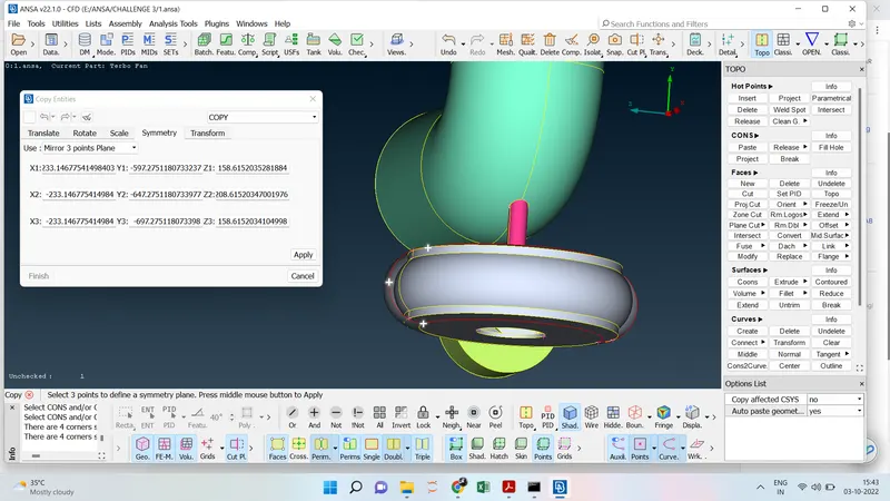
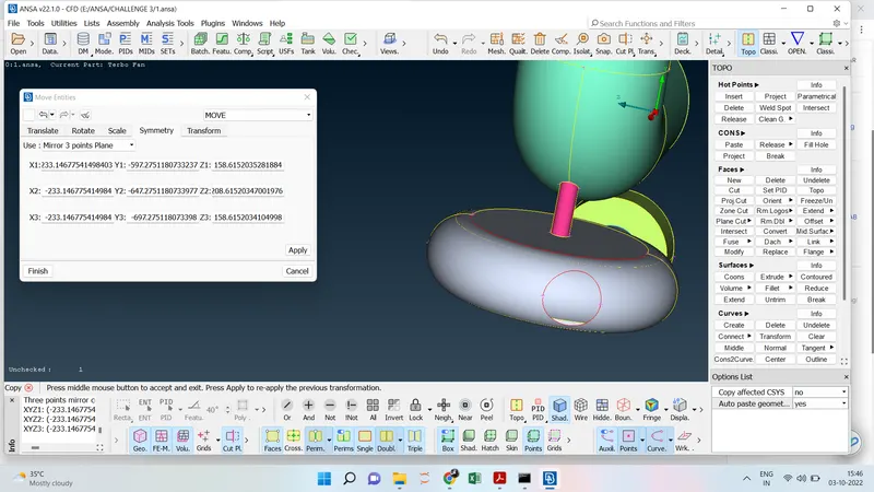
- For this missing surface, we have to create the Hotpoint in between the two hot points and Click Transform (From the Deck) ----> Copy ---> Entities ---> Select the surface to mirror ----> Symmetry ---> Mirror Three Point Plane ----> Select the Three Hotpoints ---> Middle Click ----> Click Ok.Then click Cons ----> Fill Hole ---> Middle Click.
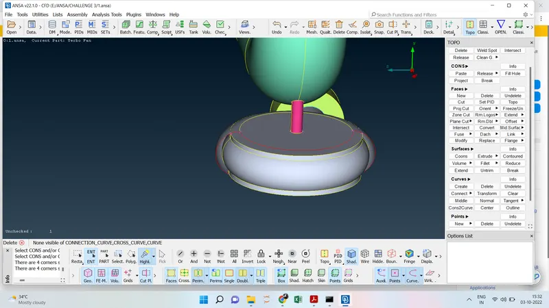
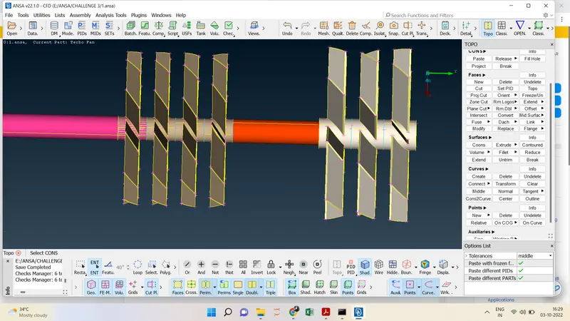
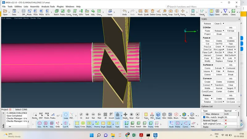
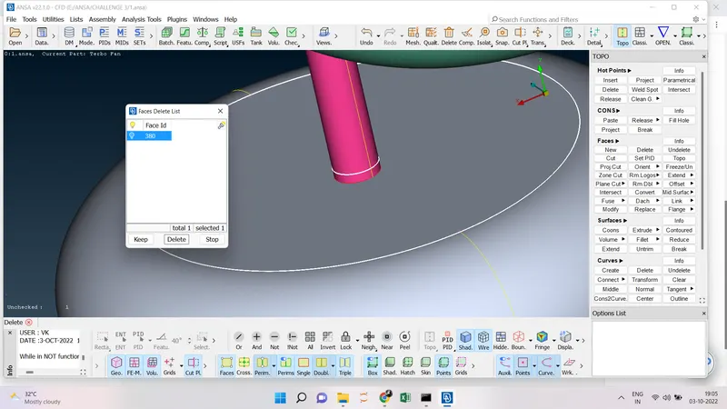
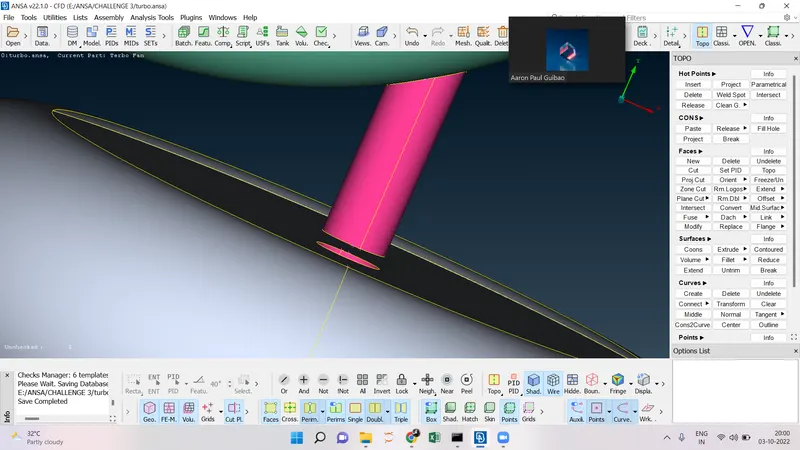
- To reduce the intersection error between the shaft and the compressor blade so we have to hide the compressor blade and delete the unwanted surface it has to be done for the three cons present in the shafts.
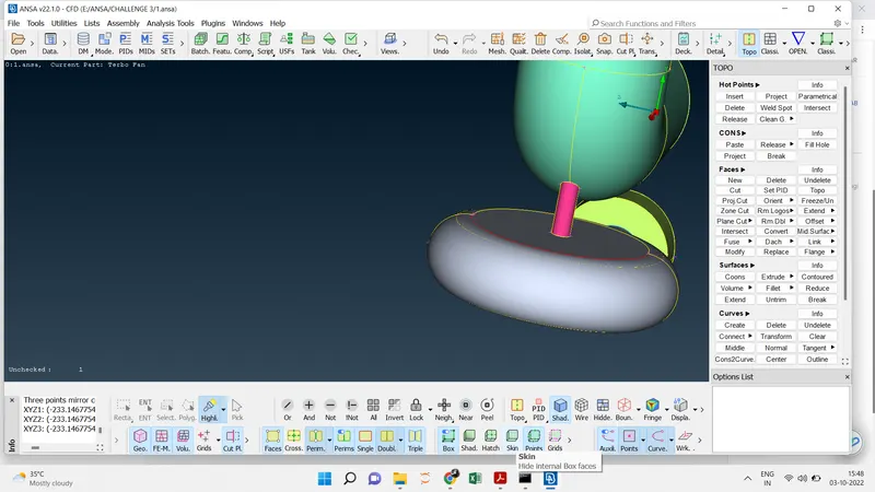
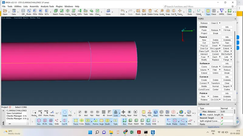
- To delete the Intersecting surface of the pink shaft and the grey shaft we have to go to Cons ---> Project ---> Loop ----> Select the Cons ---> Select the Face and the middle then using Faces ---> Delete and then all the triple cons on the shaft will be eliminated.
- The intersection error is removed from the Shaft by Face ----> Delete ----> Select the Surface and then it will be deleted.
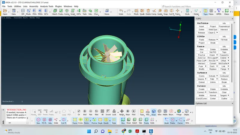
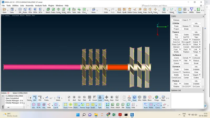
- After solving all the intersection errors last we go for the geometry check and there is no error in the model that can proceed for meshing.
- Assign the name for every PID.
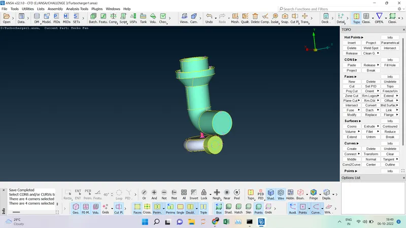
- Close all the openings before meshing.
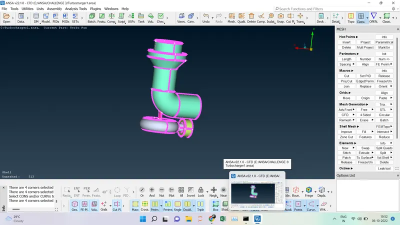
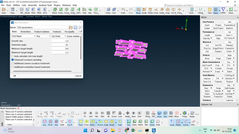
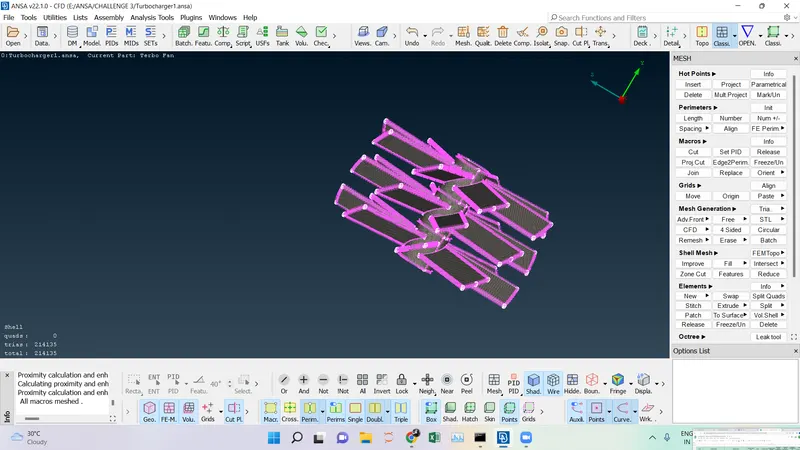
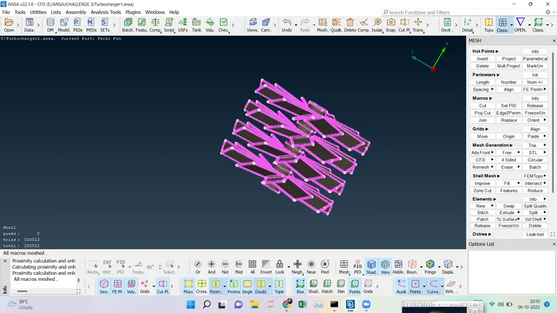
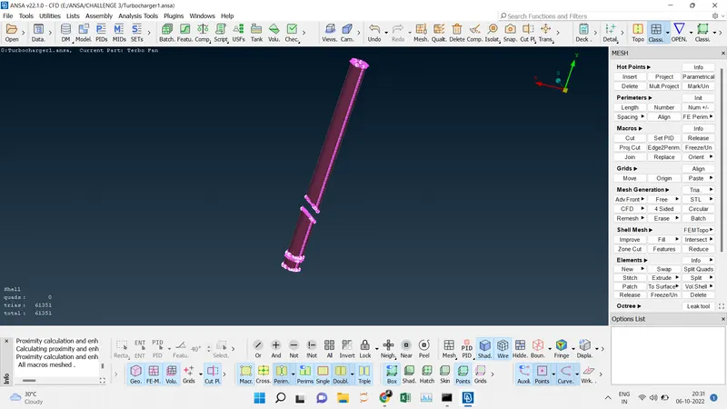
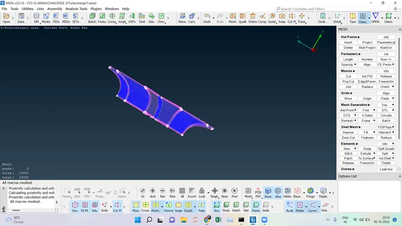
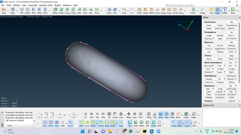
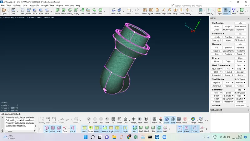
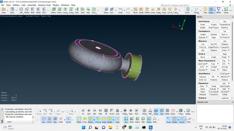
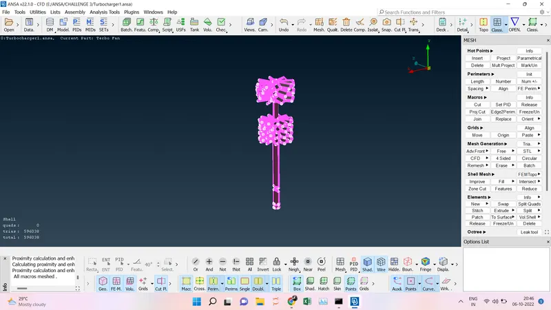
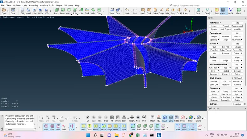
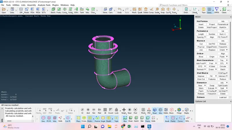
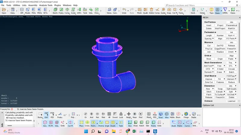
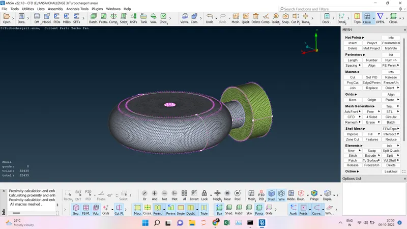
- Surface Meshing every PID has its target length we have to set that first and then go for the Mesh ----> Auto CFD ---> Perimeter and Box Select ----> Macros and Box Select ----> CFD ----> Visible. This step will be done for every PIDs.
- Blade I, Minimum Target Length= 0.9 mm and Maximum Target Length = 1.1 mm.
- Blade II, Minimum Target Length= 0.9 mm and Maximum Target Length = 1.1 mm.
- Shaft Rotor, Minimum Target Length= 0.9 mm and Maximum Target Length = 1.1 mm.
- Impeller, Minimum Target Length = 1.9 mm and Maximum Target Length = 2.1 mm.
- Turbo casing, Minimum Target Length = 4.9 mm and Maximum Target Length = 5.1 mm.
- Compressor casing, Minimum Target Length= 4.9 mm and Maximum Target Length = 5.1 mm.
- Inlet casing cover, Minimum Target Length= 4.9 mm and Maximum Target Length = 5.1 mm.
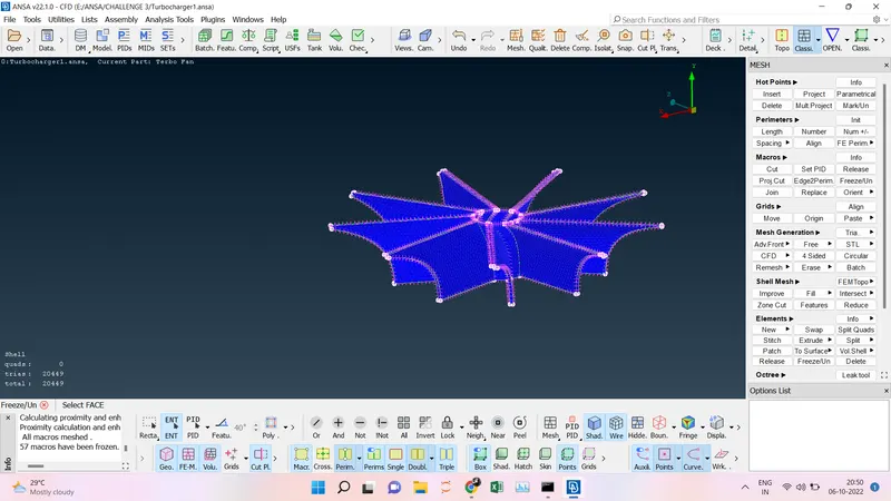
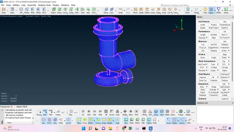
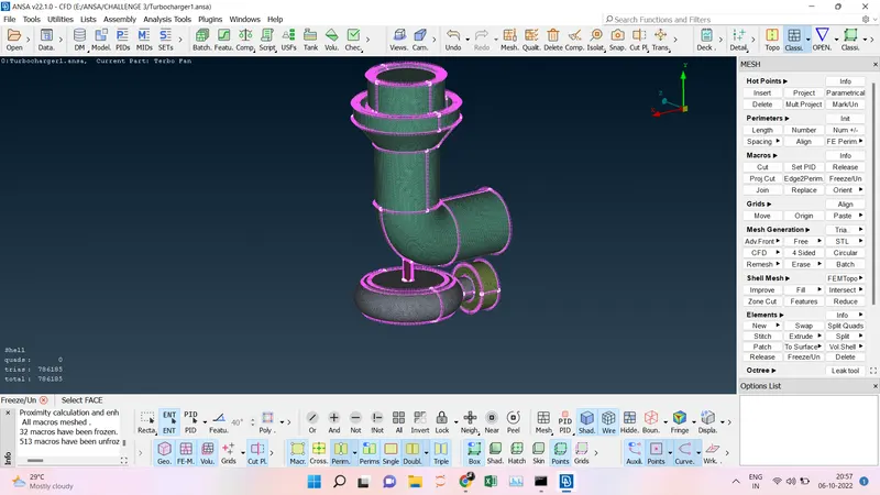
- After meshing all the PIDs there is some unmeshed surface due to the different Target lengths in the internal body and outer casing so we are going to use the freeze option here. After meshing the PIDs we are going to freeze the PIDs one by one and then click all now there will be no unmeshed surface.
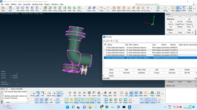
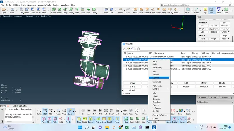
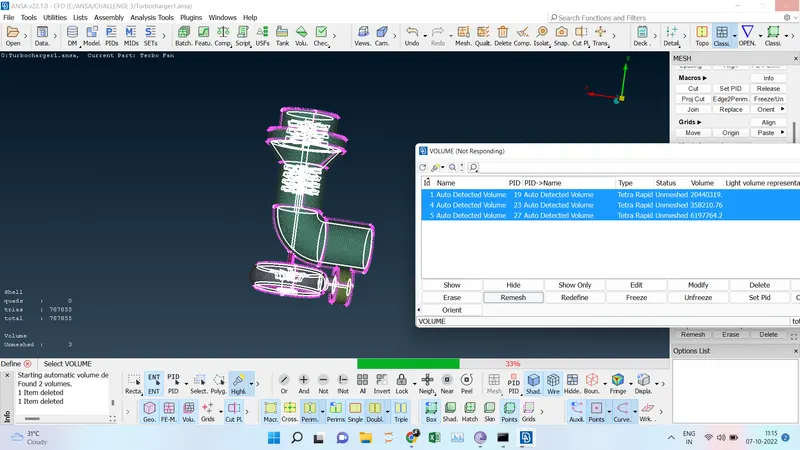
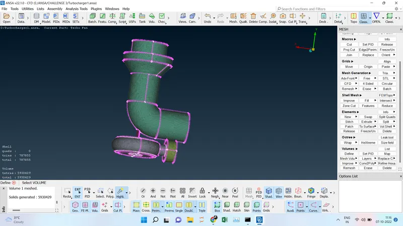
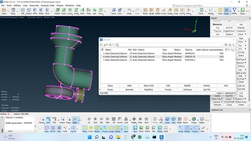
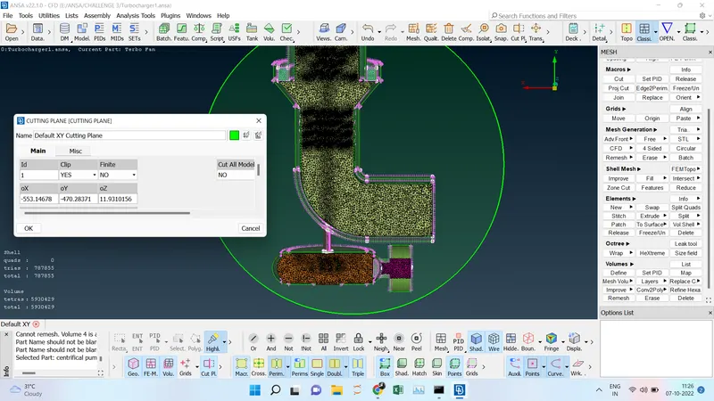
- Before performing the volume mesh we have to unfreeze by Right Click Box select after that go to Volume Mesh -----> Define and then leak detection test will be performed the test is ok it will show where the mesh area has to be done. So we are going for the Inner volume meshing so we can delete the outer area which is not required and select the tetra rapid mesh for all the inner meshes and give remesh then Volume mesh will be done. Using the XY cut plane we can able view the volume mesh.
1.
2.
3.1
4.
5.
6.
7.
8.
9.
10.
11.
12.
13.
14.
15.
16.
17.
18.
19.
20.
21.
22.
CONCLUSION:
- In this model, Geometry error cleanup has been done and then the intersection error has been removed.
- Every Part has been assigned to the PID and then surface meshing is done with the given target length as per the PIDs.
- All the openings have been closed and then unfreeze the model to perform the volumetric mesh and it has been successfully completed.
OUTPUT FILE LINK:
https://drive.google.com/file/d/1gQJLwL16JuhGh79kybwx1hAya0Pjvr3i/view?usp=sharing