Week 2 Challenge : Surface meshing on a Pressure valve
AIM:
- To check for the geometrical errors and perform Topology cleanup accordingly.
- To set three different target lengths as three different cases and mesh the model.
GIVEN:
- Target length = 1mm, 3 mm and 5 mm
- Element type = Tria
OBJECTIVE:
- Apply any one target length from the above at a time for the entire model as One case
- Submit 3 different models for 3 cases.
- Write a detailed report on your meshing process and also mention which case is giving good results along with the reason.
PROCEDURE:
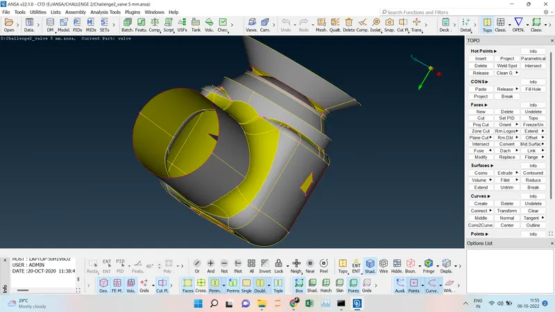
- Initially, we have to import the model to the ANSA, and then it will be visible in the wireframe model we have to click the shadow mode.
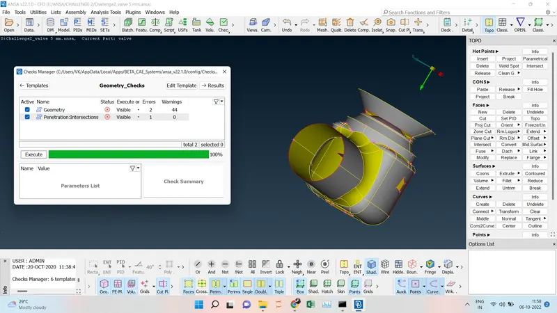
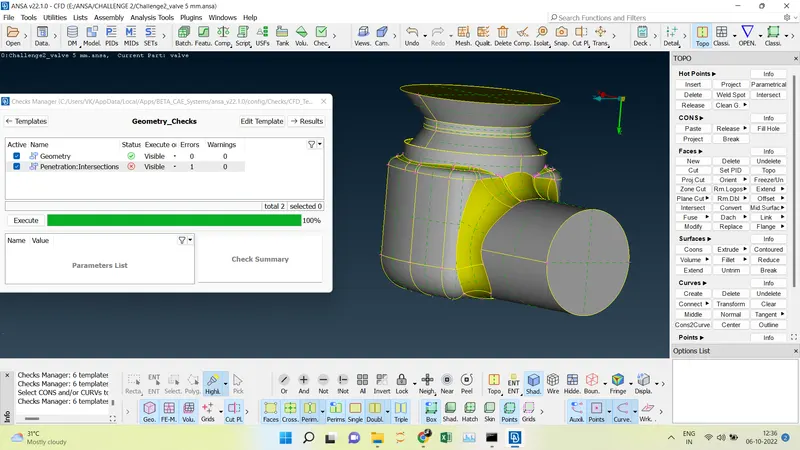
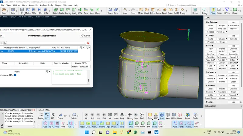
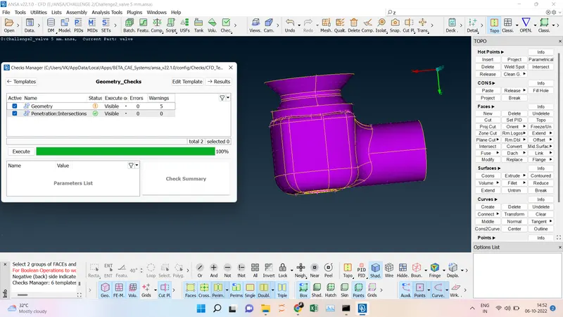
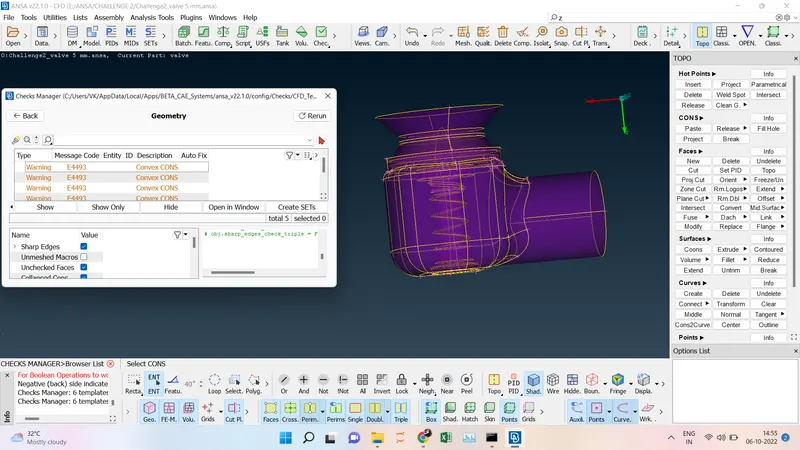
- To check the geometrical error in the model we have to click Checks---> Check Manager--->Geometry Check---> Click Execute, Here we can able find the Geometry errors in the model and Intersections in the surfaces.
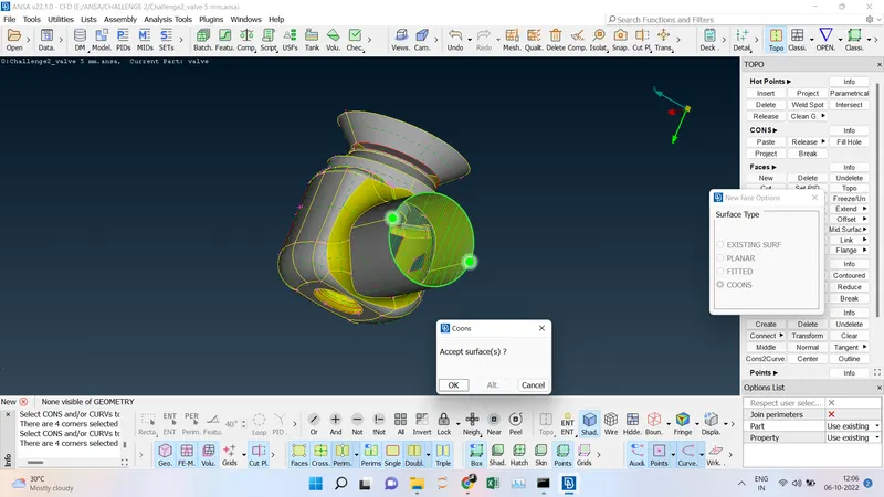
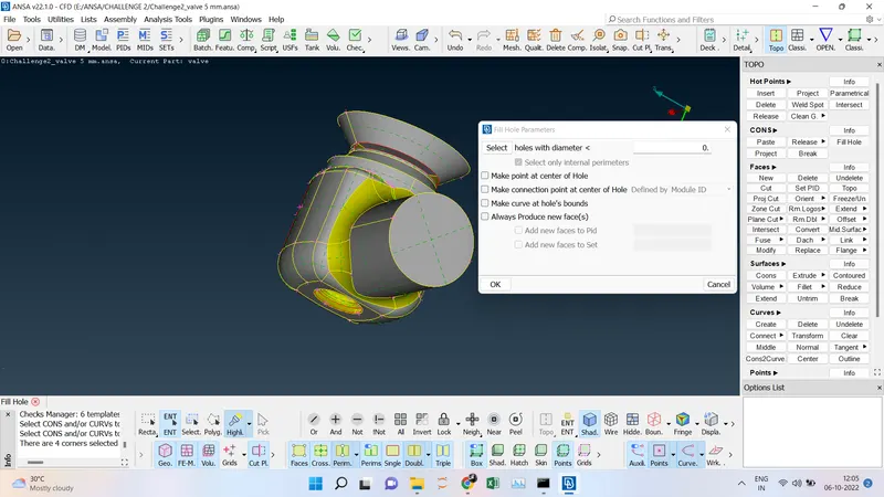
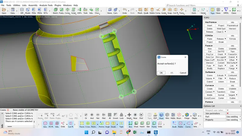
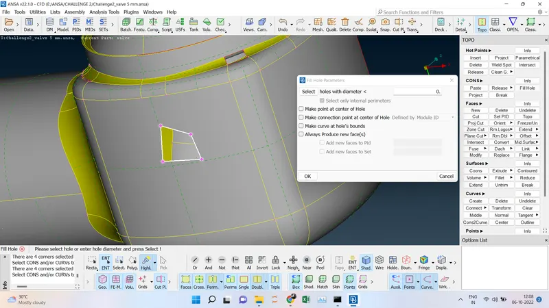
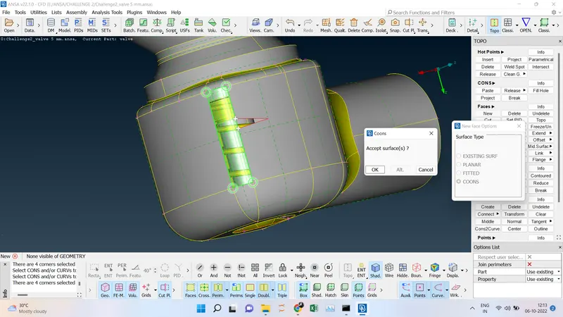
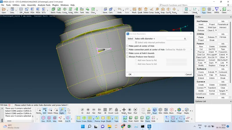
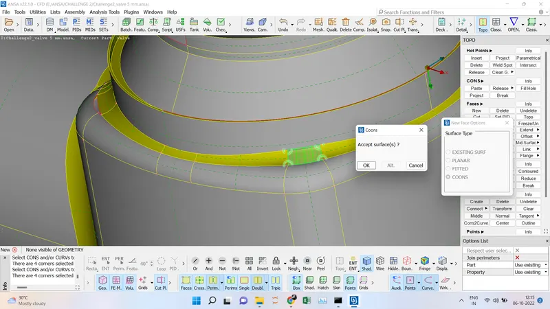
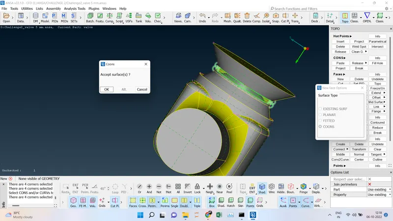
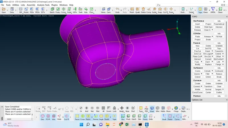
- After that to reduce the Geometry error at first we have to fill the missing surface using the Surface ----> New---> Coons ---> Loop ---> Select the surface and then middle click the Surface will be filled and there is another option to Fill the surface is Cons ---> Fill Hole ---> Select and the middle click.
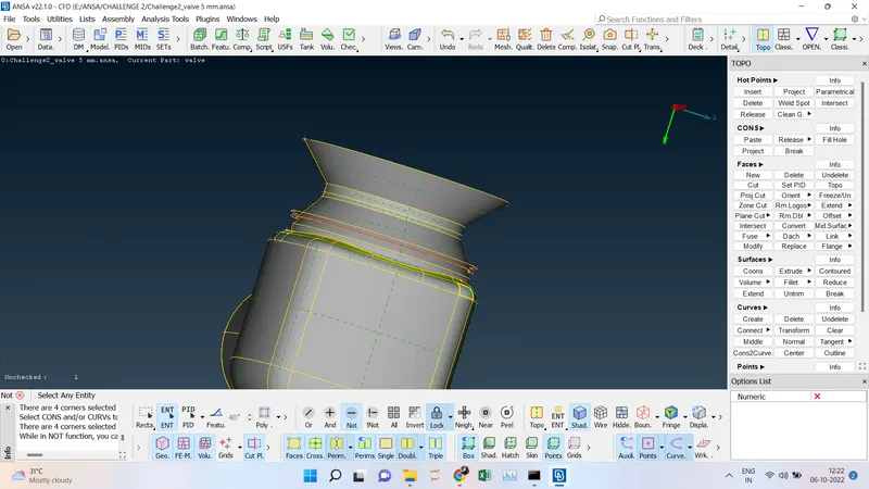
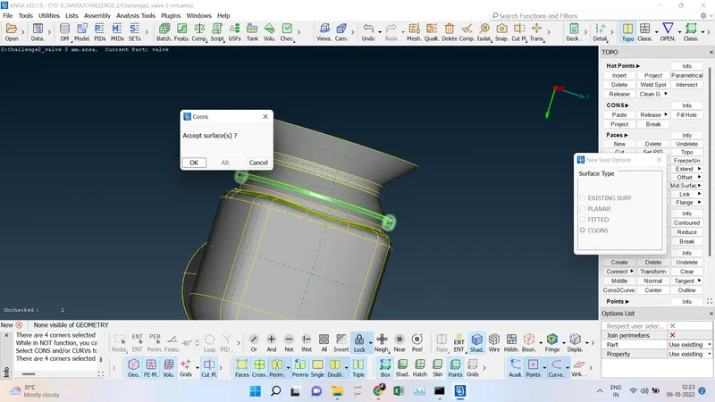
- In this face a surface missing for that we have to hide the outer surface by using the NOT and then LOCK the model and the fill surface using the COONS -----> Loop--->Select and then middle click OK.
- In this missing surface, we have used the Face ---> New----> Coons--->ENT ----> Select the Faces to fill with the middle click. Same for the second face here instead of ENT here we can able use the Loop option.
- Then go for the geometry check whether it shows any geometry error in the model by clicking execute, now the Geometry error has been cleared now it shows only the intersection error so we have to check where there is an intersection is coming from.
- There is an intersection error in the Column and the spring, so we have to delete the unwanted intersection area of the spring for that we have to define each and every part using the PID.
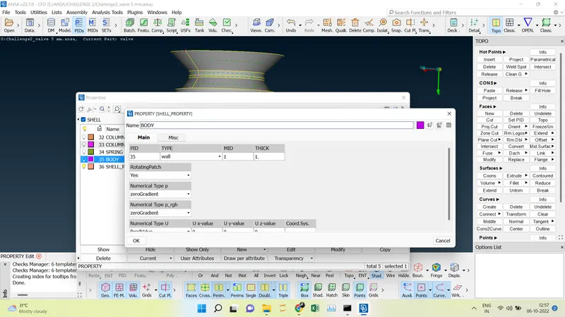
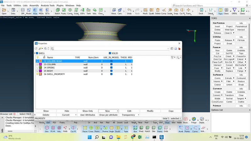
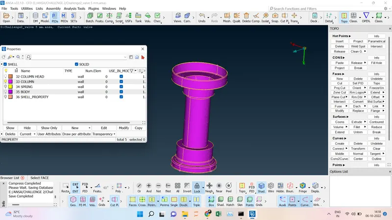
- To assign the PIDs we have to create the new PIDS, PIDs ---> Properties----> New-----> Shell Property and create the required PIDs to be assigned for the model.
-
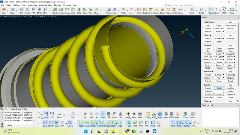
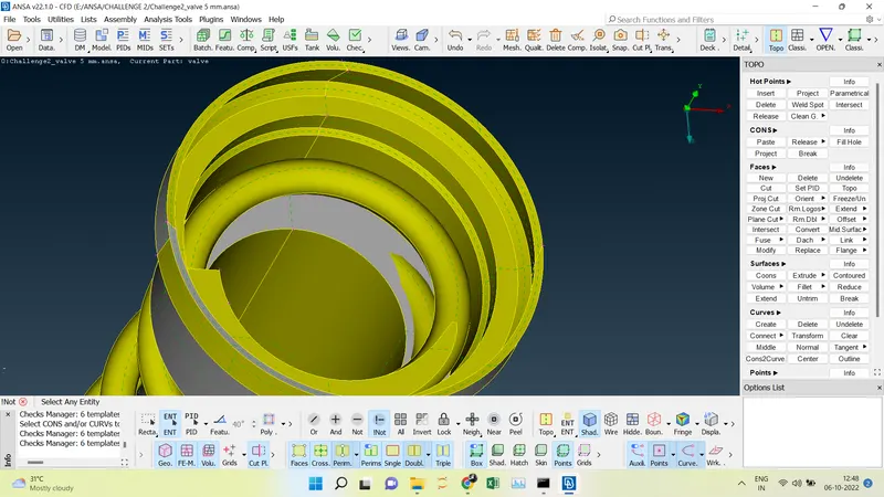
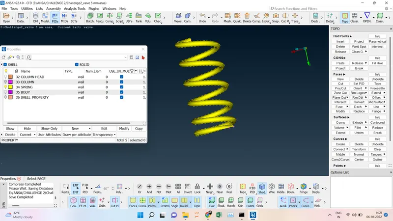
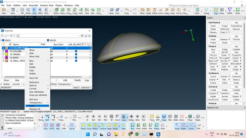
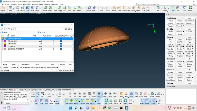
To assign the PID for the Spring we are going to use the INot option ---> select the spring ---> middle click ----> Spring will be isolated ---> go to PID ----> Clink the Spring---> Right Clink and Apply -----> Box Select the entire spring. Spring will define as a PID.
-
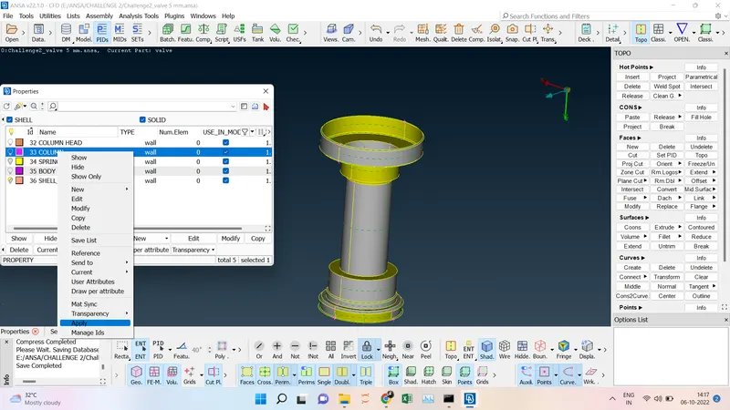
Same we are going to do for the Column.
-
Same we have to for the Column Head.
-
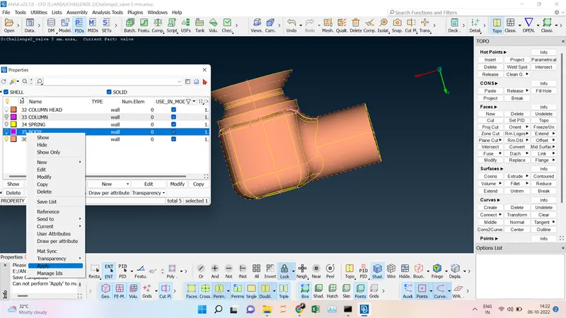
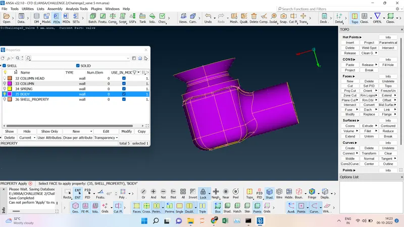
For the Body, we are going to hide assigned PIDs and use the bulb option and then right-click apply and the do the box select then Body will be assigned.
-
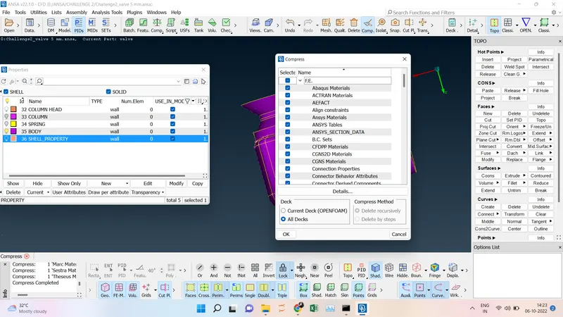
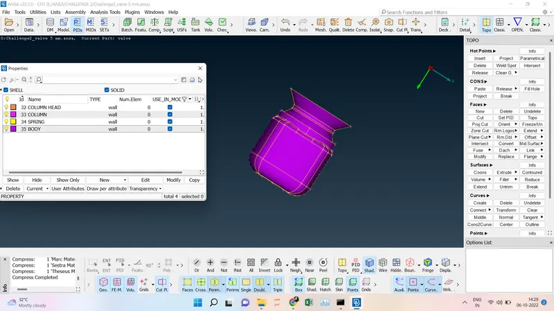
Then delete the shell property by clicking the compress option and then click ok it will be deleted from the PIDs.
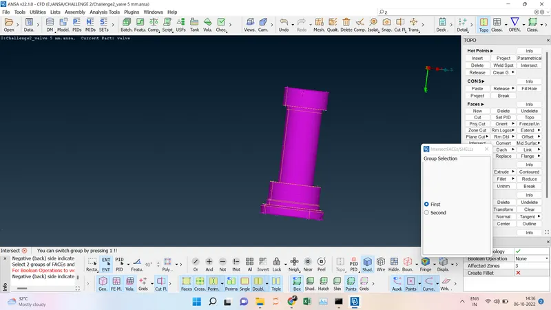
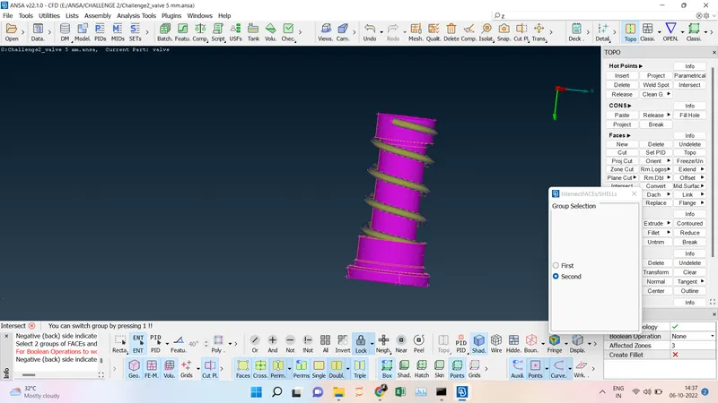
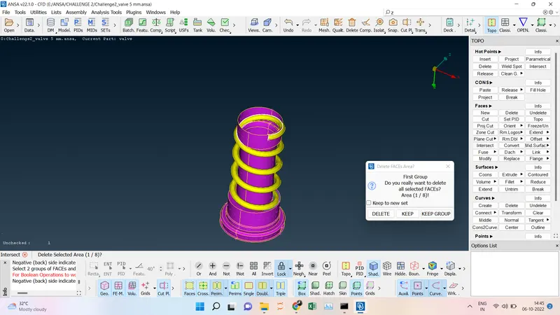
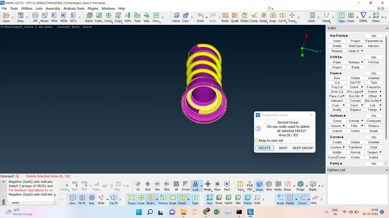
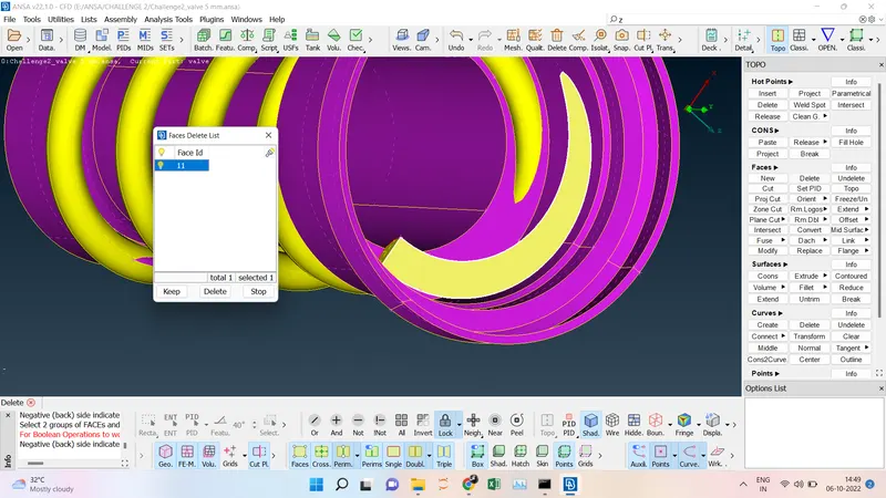
- For the intersection between the column and the spring we have to use Face option ----> Intersect ----> Select the First surface as the column ---> the second surface as the spring and then select the delete the face is not required and keep the face which you need.
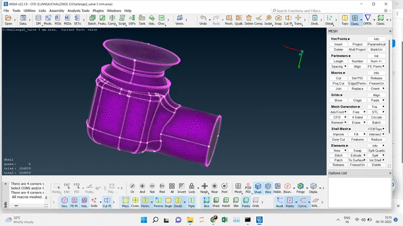
- Then hit a geometry check and there is no geometry error but convex cons are there for that we going for the mesh for 5 mm, 3 mm, 1 mm and there is no intersections error also.
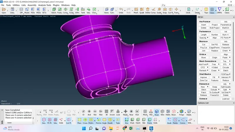
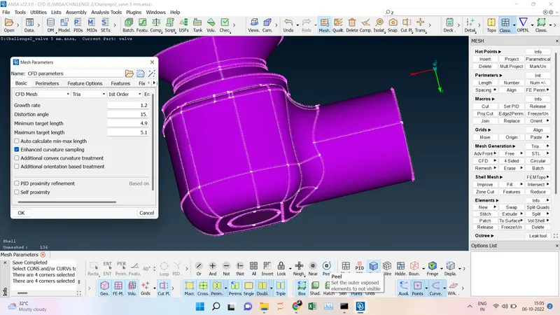
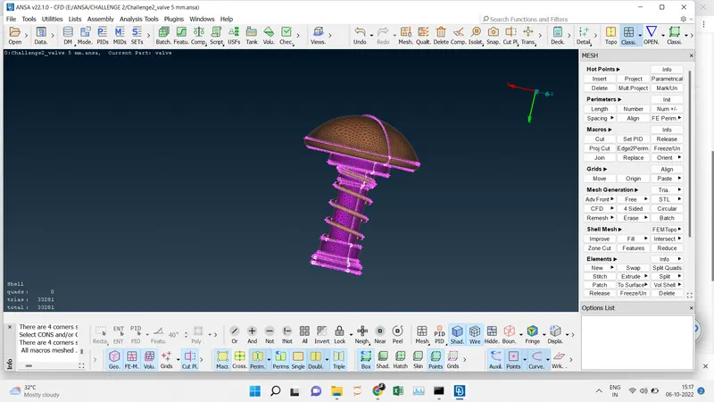
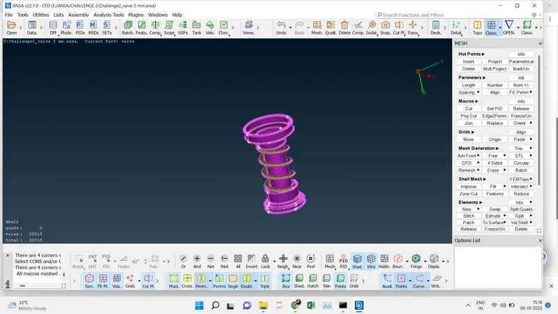
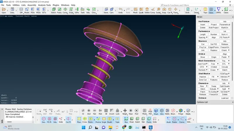
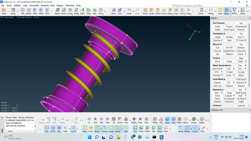
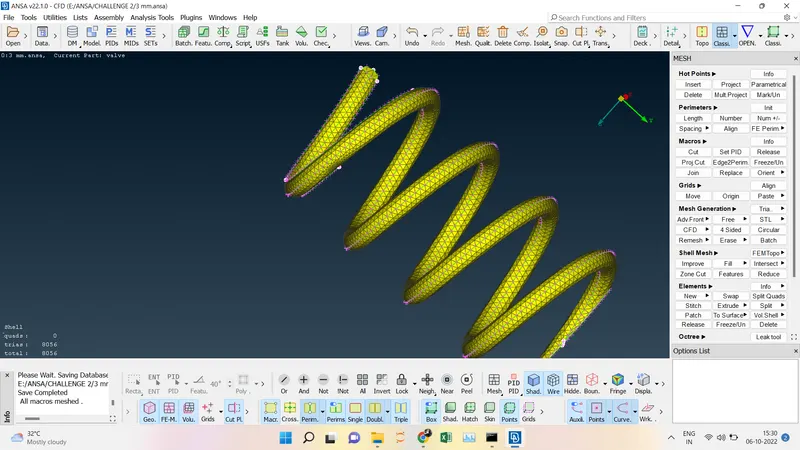
- To do the meshing we have to close the open surface and then go for the Classic mesh----> CFD -----> Visible
- 5 mm mesh, Mesh Parameter Minimum Targeted Length = 4.9 mm, Maximum Targeted Length = 5.1 mm.
- 3 mm mesh, Mesh Parameter Minimum Targeted Length = 2.9 mm, Maximum Targeted Length = 3.1 mm.
- 1 mm mesh, Mesh Parameter Minimum Targeted Length = 0.9 mm, Maximum Targeted Length = 1.1 mm.
1.
2.
3.
4.
5.

6.
7.
8.
9.
10.
11.
12.
13.
14
 .
.
15.
16.
17.
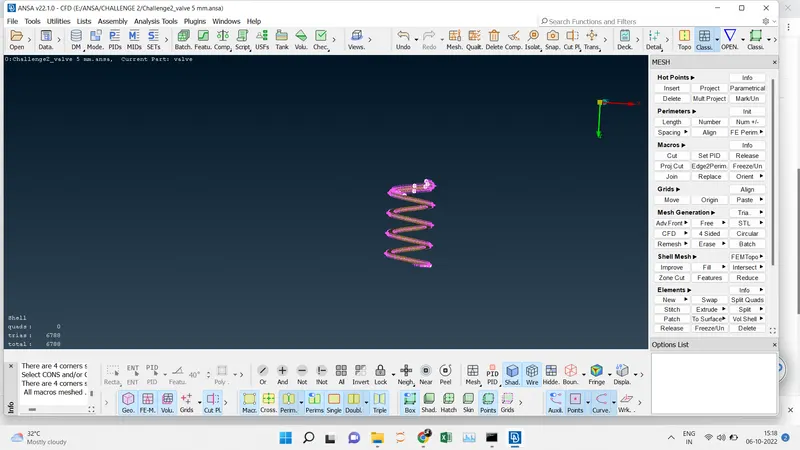
18.
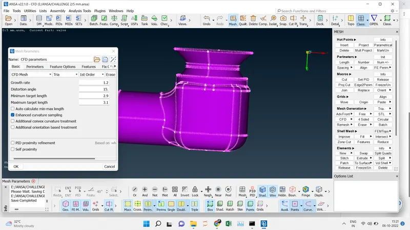
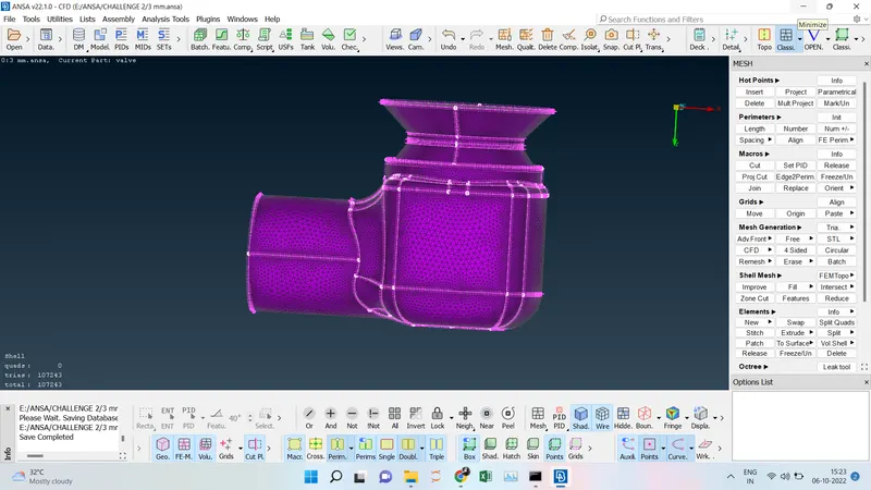
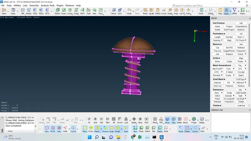
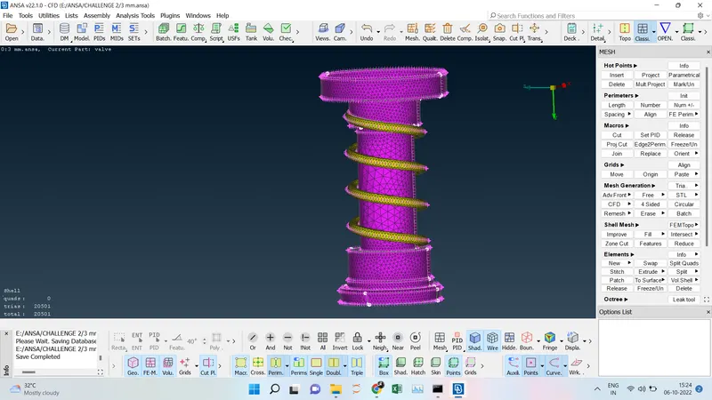
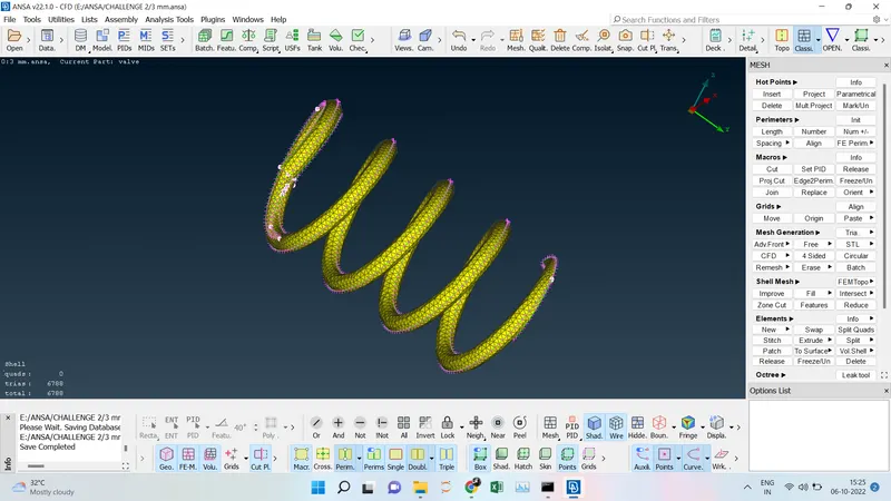
19.
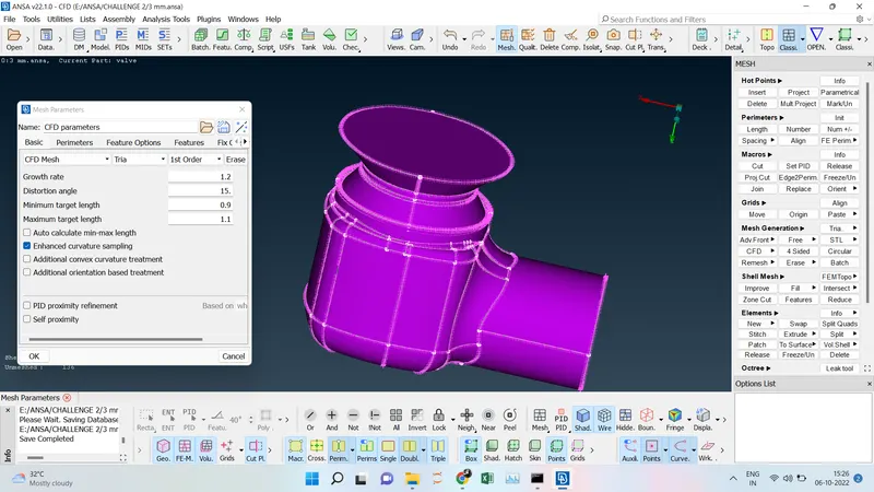
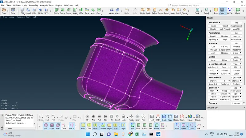
CONCLUSION:
- If we go for a fine mesh size, the accuracy will be increasing and stimulation time will also increase.
- We can make two different target lengths according to the size of the parts and the required accuracy. In this case, the outer casing mesh size can be 3mm which is not so large and not that fine earthier for a good and accurate result.
- For the smaller parts like the spring and the column head, the mesh length can be 1mm so the accuracy for smaller parts will increases.