Week 3 Challenge : CFD meshing on Turbocharger
AIM: To create surface meshing & Volume meshing process on turbo charger.
OBJECTIVE:
- To avoid or eliminate the geometrical errors and perform a topolgy cleanup.
- To set different target lengths for individual PID'S and to mesh the model.
- To perform surface mesh & volume mesh.
REQUIREMENTS:
- Element type = Tria
- Blade stage-1 = 1 mm
- Blade stage-2 = 1 mm
- Impeller = 2 mm
- Shaft rotor = 1 mm
- Turbo casing = 5 mm
- Compressor casing = 5 mm
- Inlet casing cover = 5 mm
PROCEDURE:
- Open the ansa software
- import the model
- press ctrl+shift>to view the wire frame and visualise the erros called single cons and triple cons>esc.
- click cross sction to turn on or off the cross sections>esc.
- click peirm to turn on or off the single,double,triple cons>esc.
- click not>select pid or pid region or select ent>to select the model parts individually.
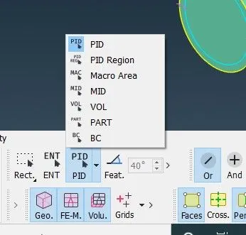
- click shadow and wire to view the model in wire frame or solid>esc.
- cliick on not,and to hide and unhide the model>esc.
- click on all to retrive the entire model at a time>esc.
- click on lock to lock or freeze the interface.>esc.
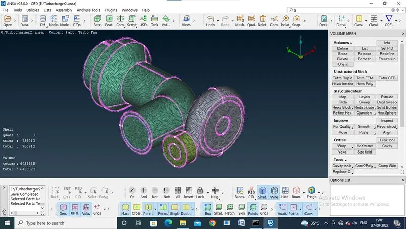
- select views section>select isometric view> clickon>esc>to visuailise the model in a 3D
- select checks section> select checks manager>excute>double click on >esc>to find and view the geometrical errors and intersection.
- click on topo section to clean up the geometrical erros.
- click on topo section>select faces >click new>to generete the coons,fitted,planar,and existing surfaces,to use eliminate errors>select cons>middle click>esc.
- click on intersect >select the 1st faces >middle click>select 2nd face>middle click>keep and delete the faces >esc.
- click on cut >select the points > to create the cons>use the delete to eliminate the error>esc.
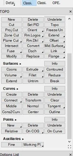
- select delete >to delete unwanted sections or faces>select face>middle click>esc.
- click on cons > select the fill hole to fill the entire error on surface>select cons>middle click>esc.
- click on pid properties>right click>click on new>>click on shell property>create the shell propertys with names> assign colors if needed>select cross scetion or face >middle click >to assign the pid>esc.
- use pid's to hide or unhide the parts or shells>click on bulb>esc.

- select intersect >select the 1st face>middle click>select 2nd face>middle click>delete or keep the faces if needed>esc.
- select the cut>select cons>select face> middle click>esc.
- click topo>select the model>middle click>esc>to avoid erros and joins the cons.
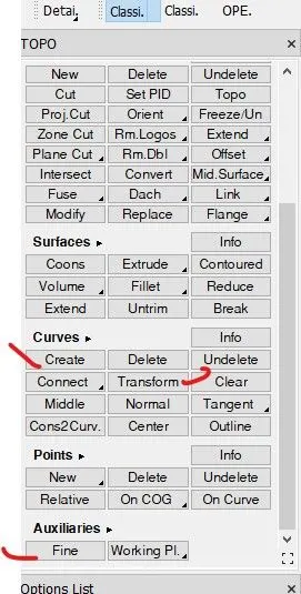
- click on curves>select create> select points>middle click>esc> it creates temporary cons and curves
- click delete>select curve>middle click >delete
- click on curves>select transform> select points>middle click>esc> it creates temporary cons and curves
- click on axuiliaries>select fine>select cons>adjust the cons by right click>esc.
- finish the topology clean up and assign after pid's then shift to mesh
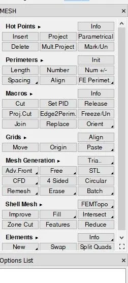
- click on mesh section to create surface mesh.
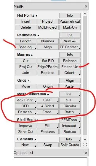
- click om mesh section>select perimeter>click on spacing>select auto cfd>click on perimeter >select model>add lengthg>middle click >click macros>select model>middle click>esc.
- click on mesh >add max length>add min length>put cfd mesh>keep tria>ok>esc.
- click quality >add max length>add min length>ok>esc.
- click compress >click ok>esc.>to remove unwanted shells.
- select generate mesh>click cfd or spot>select visible>mesh completed.
- change the lengths to increase the quality of the mesh.
- use freeze and unfreeze command on model to control the mesh errors.
- use free command to mesh the model with unstructured mesh.
- click on freeze or unfreeze>right click>drag the model to select>middle click>esc.
- click on free>select face>middle click>mesh generate>esc.
- click on erase>select face> middle click>mesh erased>esc>to delete the periviously created mesh.
- after the surface mesh done,then turn to volume mesh.
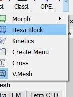
- click on volume mesh section to create volume mesh
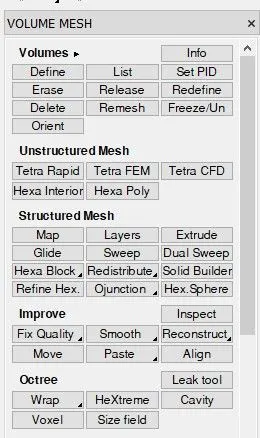
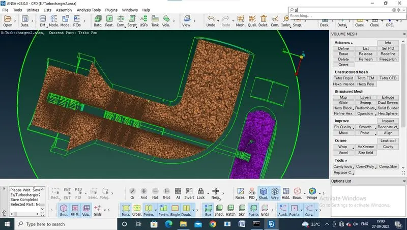
- click on volume section>select define>popup showed>press ok>popup showed,select the volume mesh parts>double click>popup showed>keep the changes >select tetra cfd>press ok>right click >select mesh>mesh generated>esc.
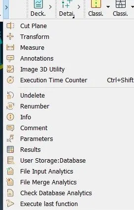
- use the cut plane to visualise the model intersection & mesh generated.
- click on cutplane>select new >select the axis>middle click>popup showed>select new part>double click>intersection showed>esc.
LEARING OUTCOMES:
- how to use transfrom command on model.
- how to use intersect command on model.
- how to use create command on model.
- how to use freeze/unfreeze command on model.
- how to use cut plane command on model.
- how to use pid region ,ent,loop,pid command on model.
- how to use free command on model.
- how to use erase command on model.
- how to use spacing command on model.
- how to use fine command on model.
- how to use define command on model.
RESULTS:
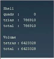
SURFACE MESH:
VOLUME MESH:
LINK:
https://drive.google.com/file/d/1pot6Mb80iqPU4duIHsqamWtah47Sbnv6/view?usp=sharing
CONCLUSION:
when the quality of the mesh increased the length of the element were decreased and its take compactability time when the length decreased,to mesh the model,and the flow generated in mesh state and its consumes the lots of space in memory .