Week 3 Challenge : CFD meshing on Turbocharger
Aim/Objective
For the given model:
- To check for the geometrical errors to make appropriate volumes.
- Create and assign PIDs.
- Perform surface mesh with the given target lengths as per PIDs.
- Perform Volumetric mesh for the required volumes.
Procedure for surface meshing & Volume meshing process
> Geometrical errors are solved in Topo mode.
> PIDs are created and assigned for the required volumes after solving geometrical errors.
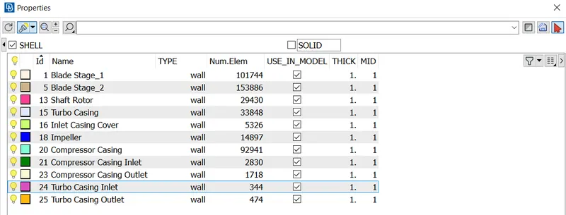
> As Surface mesh is pre-requisite of volumetric mesh such that surface mesh is performed with the given target lengths as
per PIDs.
> Target length is specified in material properties for different PIDs:
- Blade stage_1 = 1 mm
- Blade stage_2 = 1 mm
- Impeller = 2 mm
- Shaft rotor = 1 mm
- Turbo casing = 5 mm
- Compressor casing = 5 mm
- Inlet casing cover = 5 mm
> After surface meshing volumetric mesh is performed for the required volumes.
> Volumes are defined by:
Volumes --> Define --> Detect on: Whole db
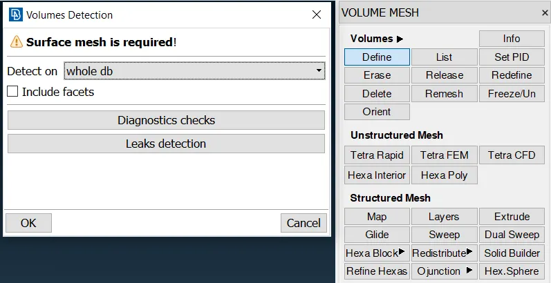
> After detecting volumes only the required volumes are prefered for volumetric mesh.
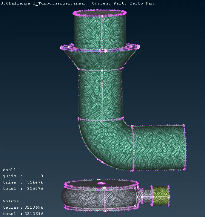
> Tetra CFD mesh is used for volume meshing.
Results
Volumetric meshed model for the required volumes
> Cut section view after volumetric mesh is given below:
xy_cut plane
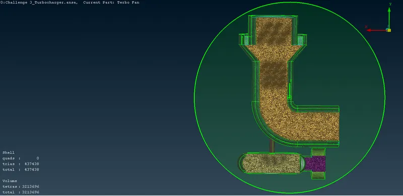
yz_cut plane
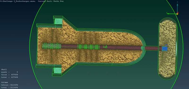
ANSA model of turbocharger:
https://drive.google.com/file/d/1QIJs5zVZhPOXhA2qcDAAetIDjHhpZKJG/view?usp=sharing