Week 3 Challenge : CFD meshing on Turbocharger
AIM:TO DO CFD meshing on Turbocharger
OBJECTIVE: For the given model, check for the geometrical errors to make appropriate volumes. Create and assign PIDs as shown in the video. Perform surface mesh with the given target lengths as per PIDs.
- Blade stage-1 = 1 mm
- Blade stage-2 = 1 mm
- Impeller = 2 mm
- Shaft rotor = 1 mm
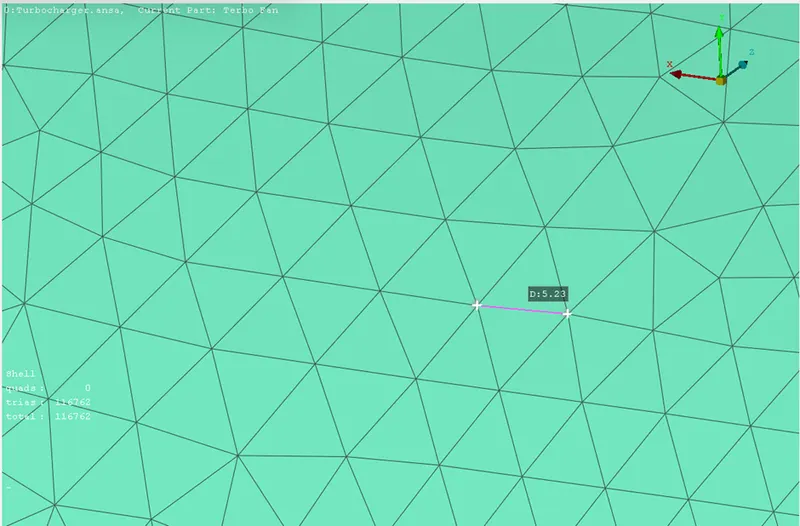
- Turbo casing = 5 mm
- Compressor casing = 5 mm
- Inlet casing cover = 5 mm
Perform Volumetric mesh for the required volumes
EXPLANATION:
SURFACE MESHING: The surface mesh is a representation of a surface that consists of vertices, edges and faces. There are currently two distinct alternatives for the surface representation in the deformable meshing literature, namely triangular and simplex meshes. Triangular meshes are composed of triangle faces which share each of their edges with exactly one other triangle face.
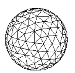
VOLUME MESHING: In 3D computer graphics and modeling, volumetric meshes are a polygonal representation of the interior volume of an object. Unlike polygon meshes, which represent only the surface as polygons, volumetric meshes also discretize the interior structure of the object. One application of volumetric meshes is in finite element analysis, which may use regular or irregular volumetric meshes to compute internal stresses and forces in an object throughout the entire volume of the object.
Process of any simulation: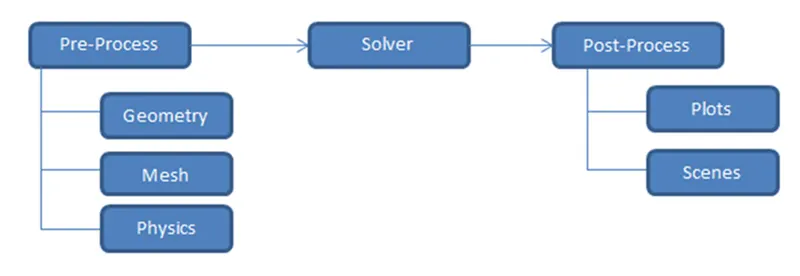
In this challenge we will be doing the pre-processing (Geometry and mesh only)of the given model in ANSA software.
PROCEDURE
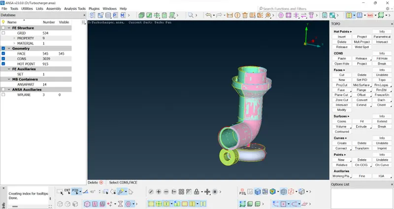
- IMPORT THE GEOMETRY TO ANSA
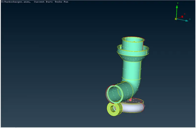
2. TO CHECK THE ERRORS IN THE MODEL
In ANSA, we can find out the errors present in geometry.This is done by using Checks command.In Checks command Geometry is selected.
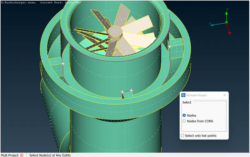
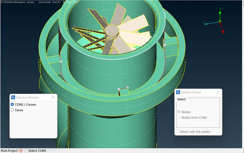
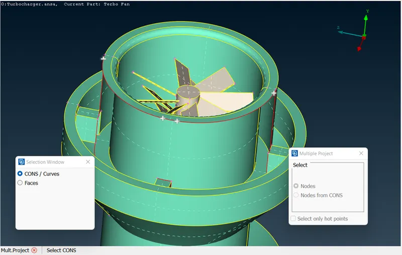
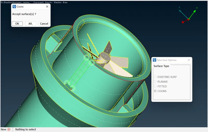
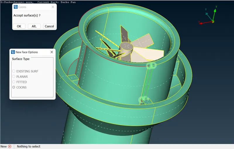
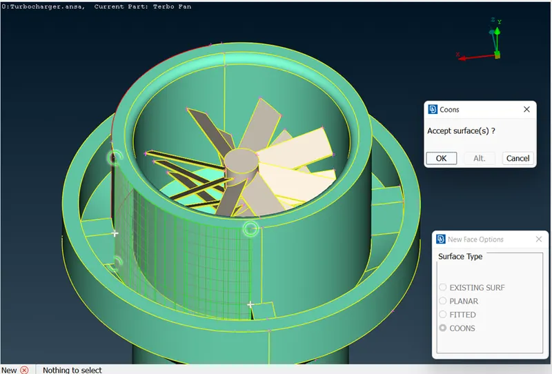
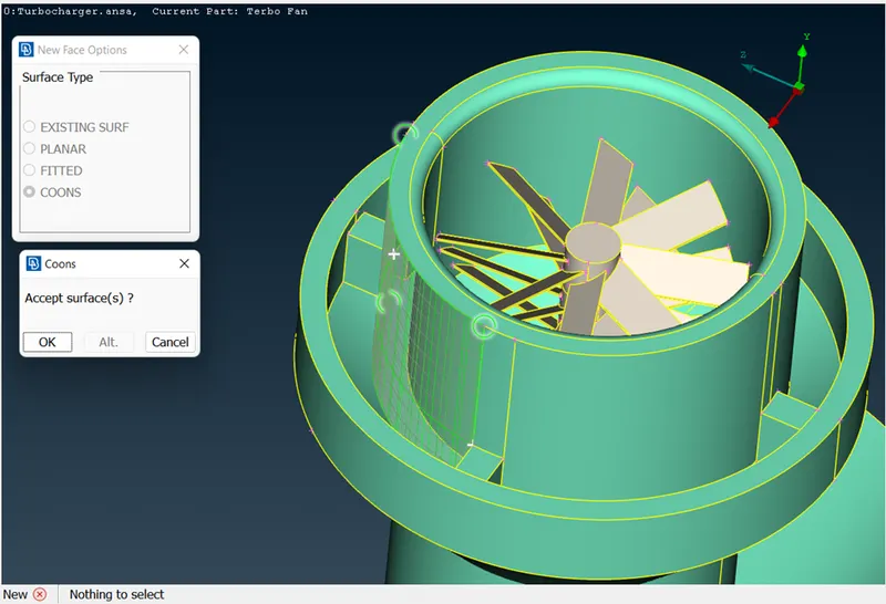
- We have to eliminate Single CONS. And TRIPLE CONS(where they are not required).AND eliminate the surface glitches.( Enable the PID view
)
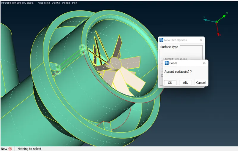
Below are some of the methods to eliminate CONS and glitches.
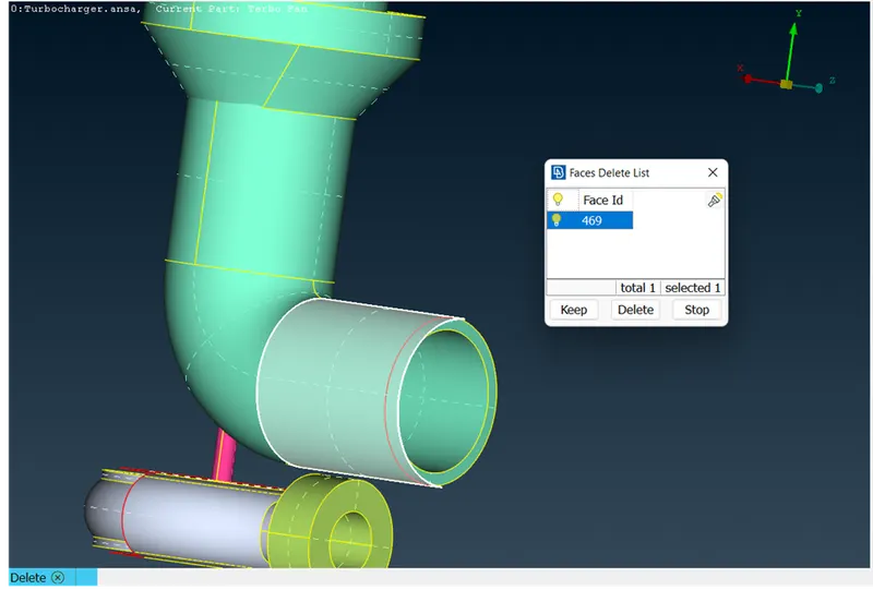
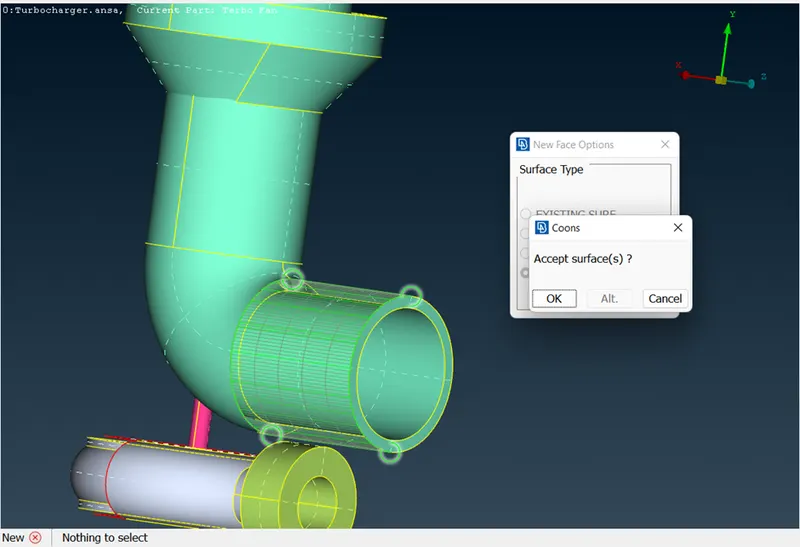
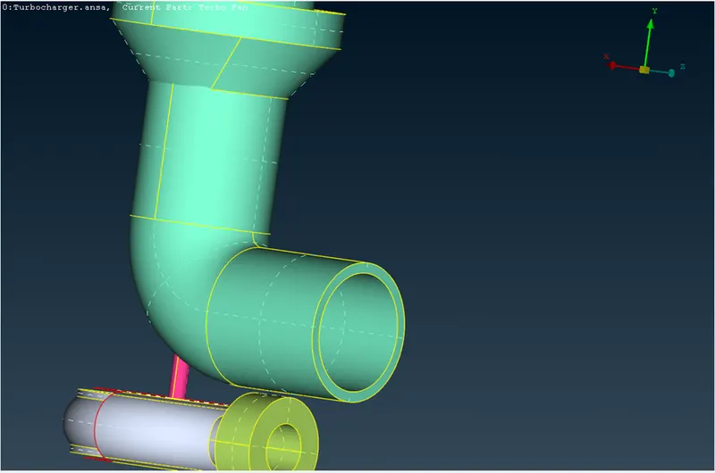
------------------------------------------------------------------------------------------------------------------------------
------------------------------------------------------------------------------------------------------------------------------
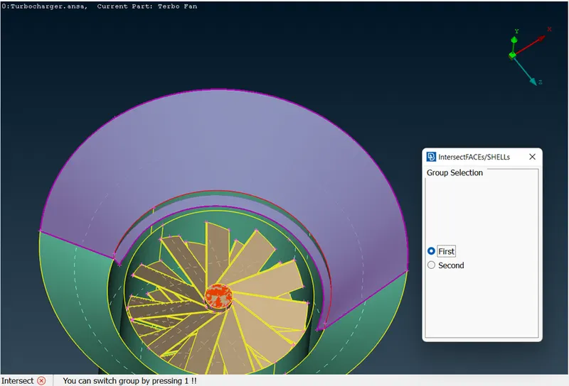
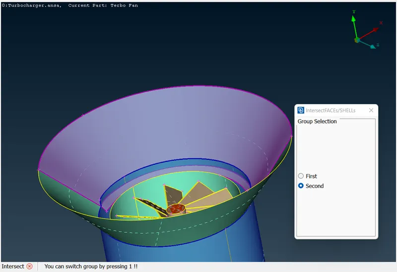
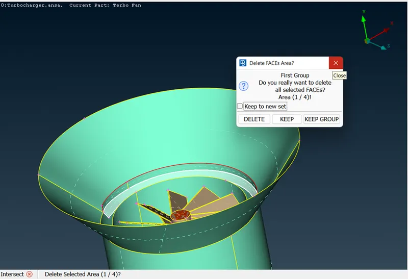
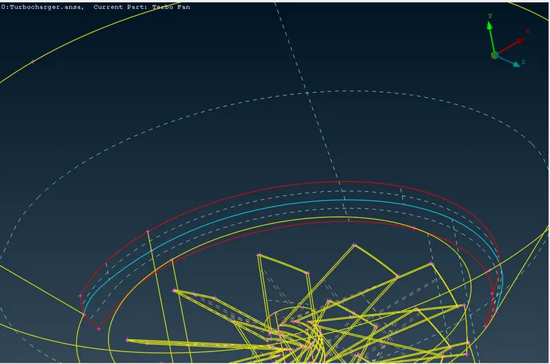
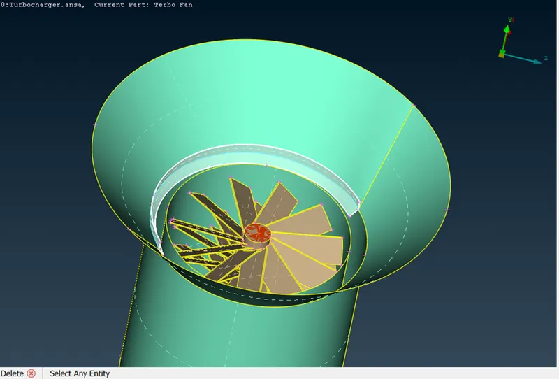
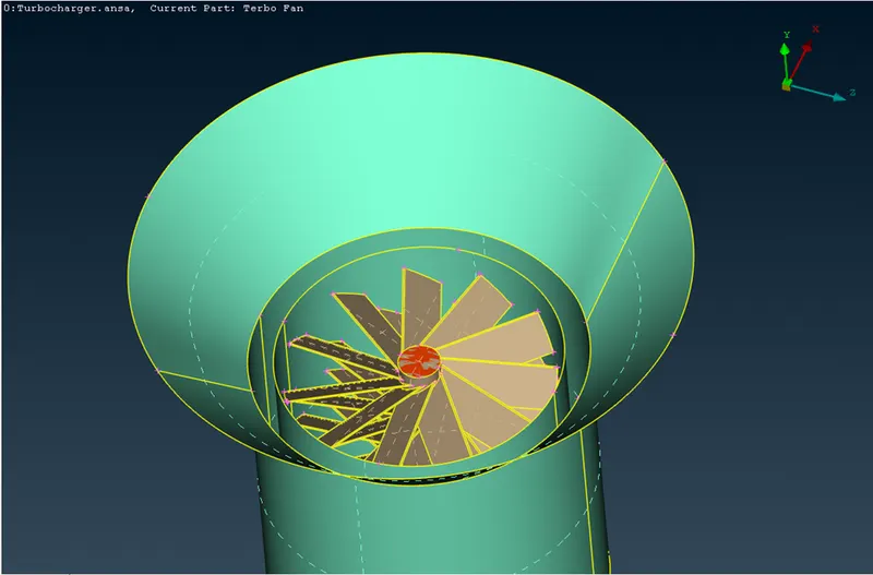
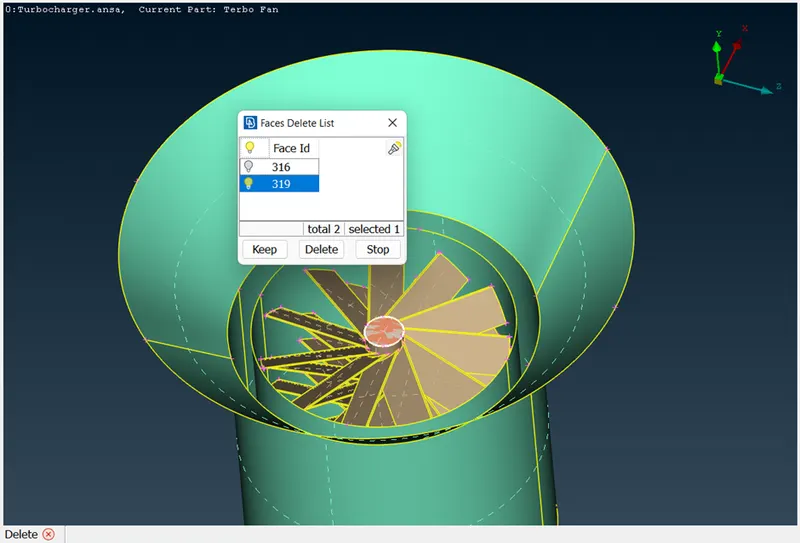
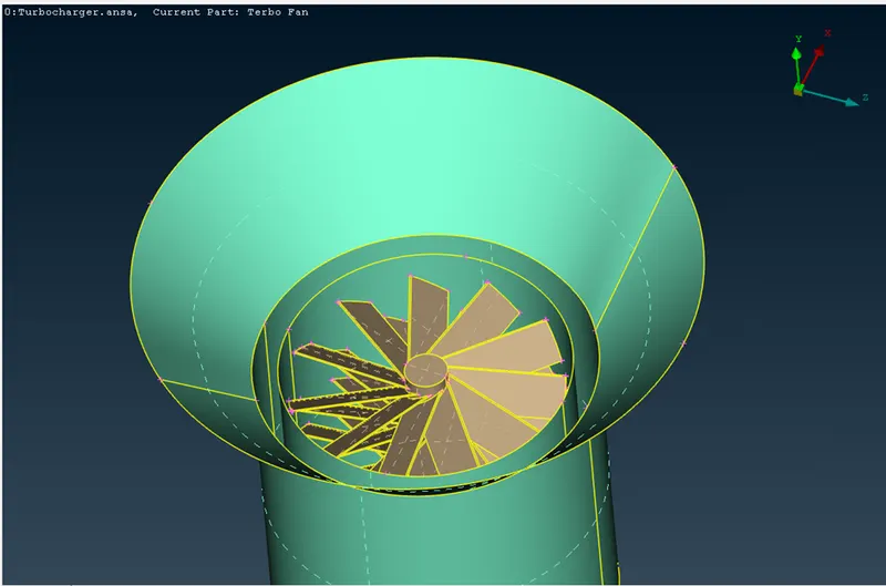
it has Triple CONS that means the surface is not connected.to eliminate the Triple CONS ,we need to delete the below two surfaces
------------------------------------------------------------------------------------------------------------------------------------------
-------------------------------------------------------------------------------------------------------------
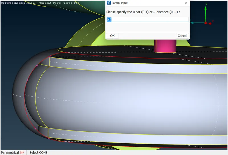
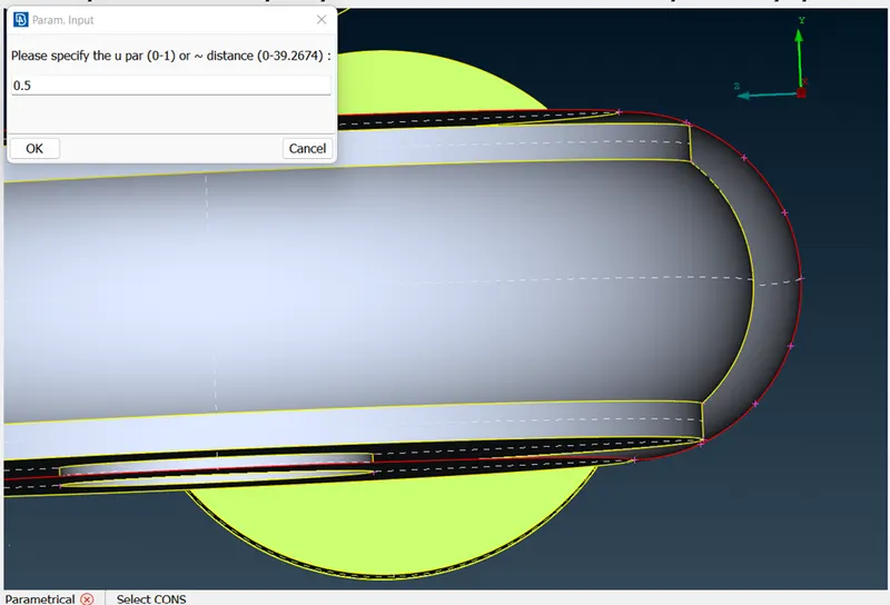
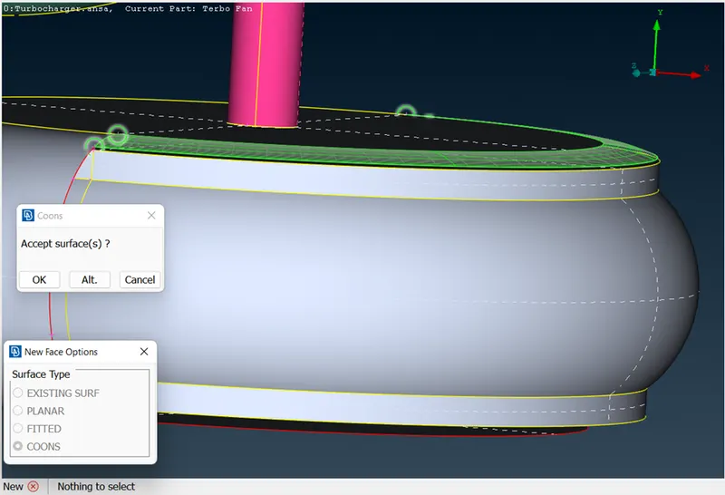
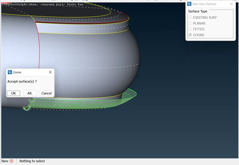
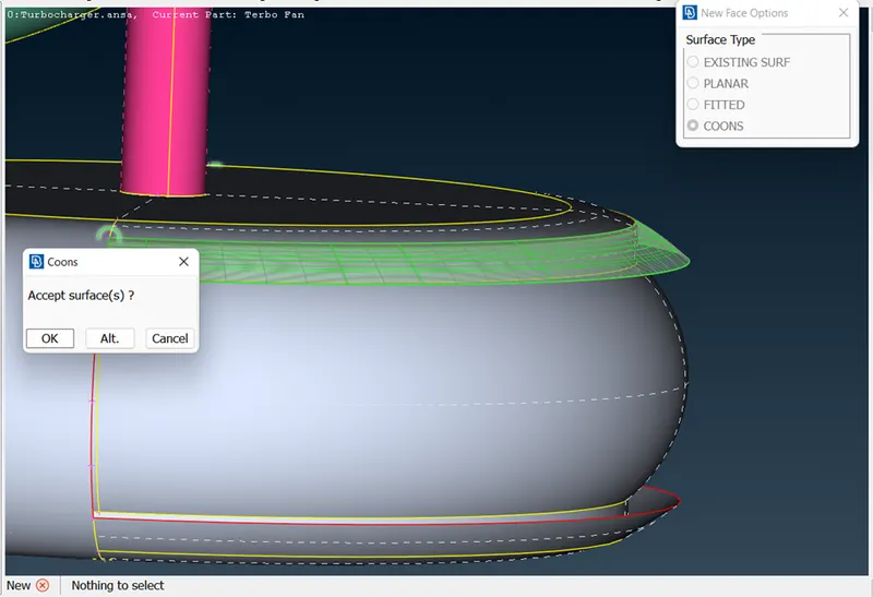
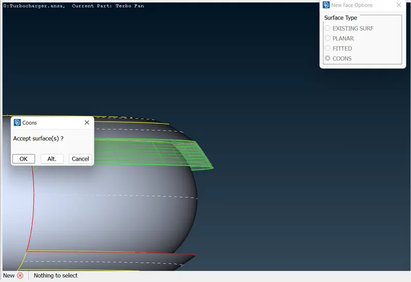
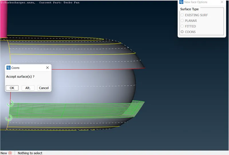
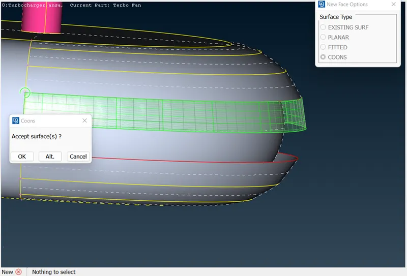
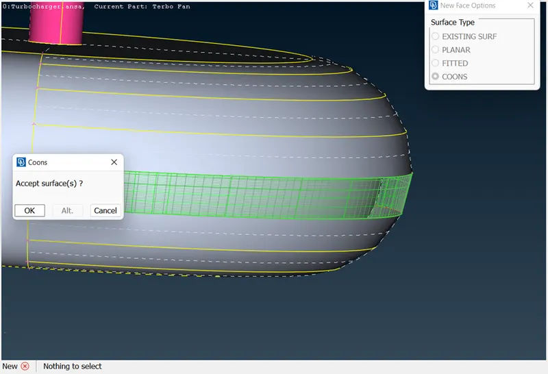
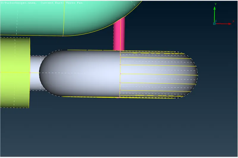
3. TO CLOSE THE GEOMETRY
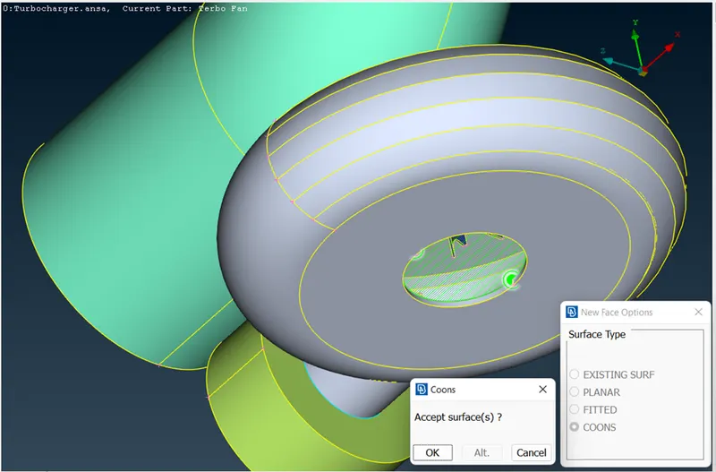
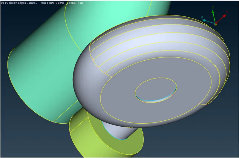
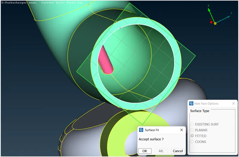
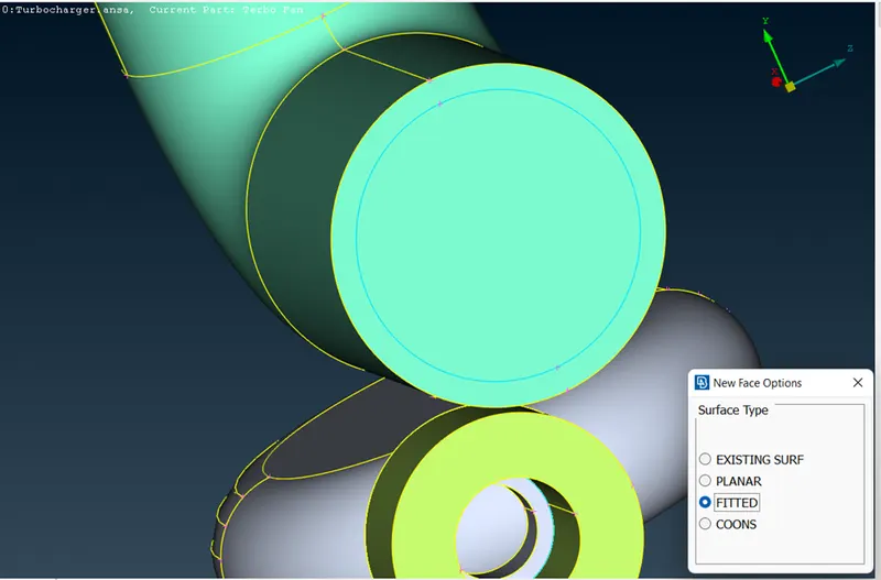
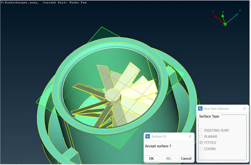
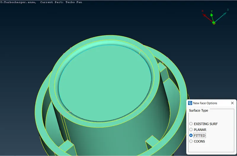
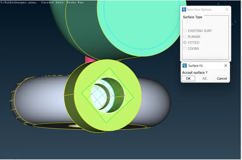
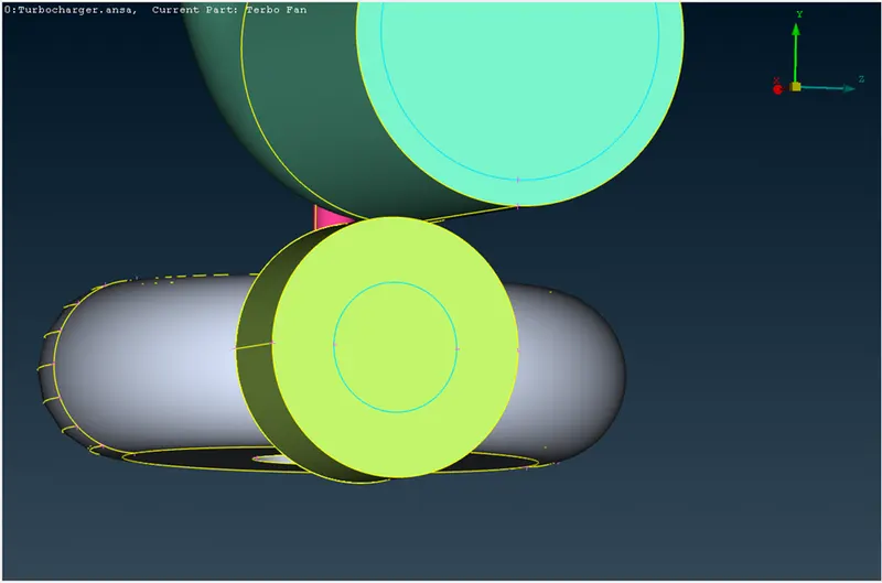
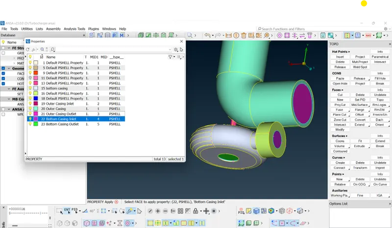
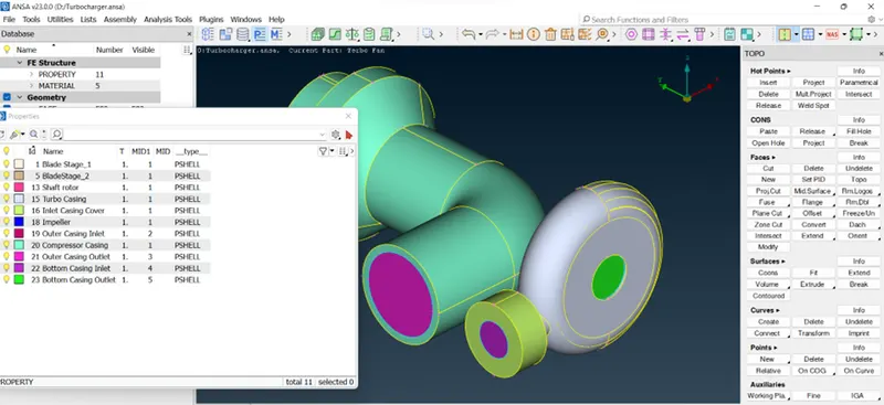
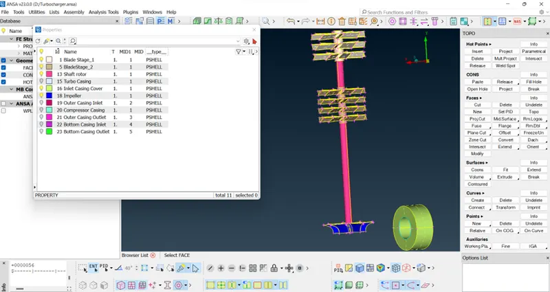
- TO DO NAME SELECTION
Now to do name selection,we can use ENT/PID/PID Region depending upon the type of selection
- Add properties (to assign boundary conditions)
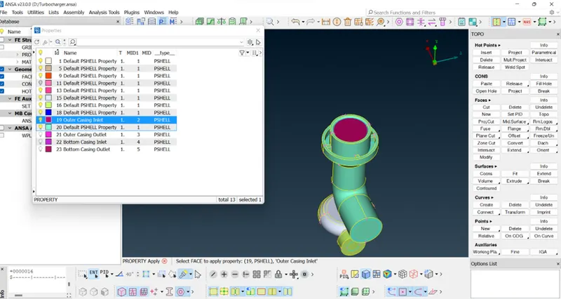
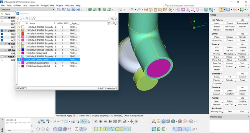
- START MESHING
We have to create a mesh having
- for this select Classic Mesh in Mesh Module.
- prop window will appear having Perimeters and Macros
- for the options we have to box select the geometry and give length as stated in the problem statement
- Perimeters-green portion
- Macros-enclosed in perimeter
- In the mesh parameters,giving target length as 1/2/5 and minimun length.
|
target length |
minimum length |
maximum length |
|
1 mm |
0.5 |
2 |
|
2 mm |
1 |
3 |
|
5 mm |
3 |
7 |
- in the quality criteria, we have to minimum length and maximum length according to target length as given in the above table.
COMPRESSOR CASING -5mm
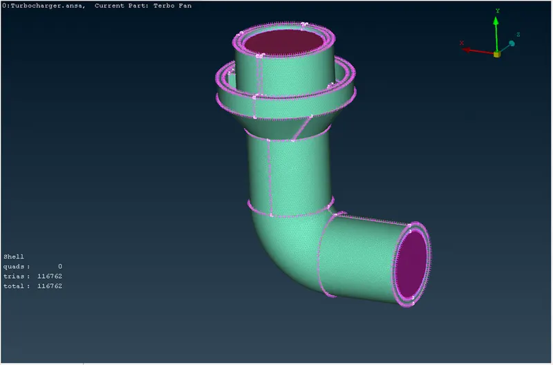
TURBO CASING AND INLET CASING COVER-5mm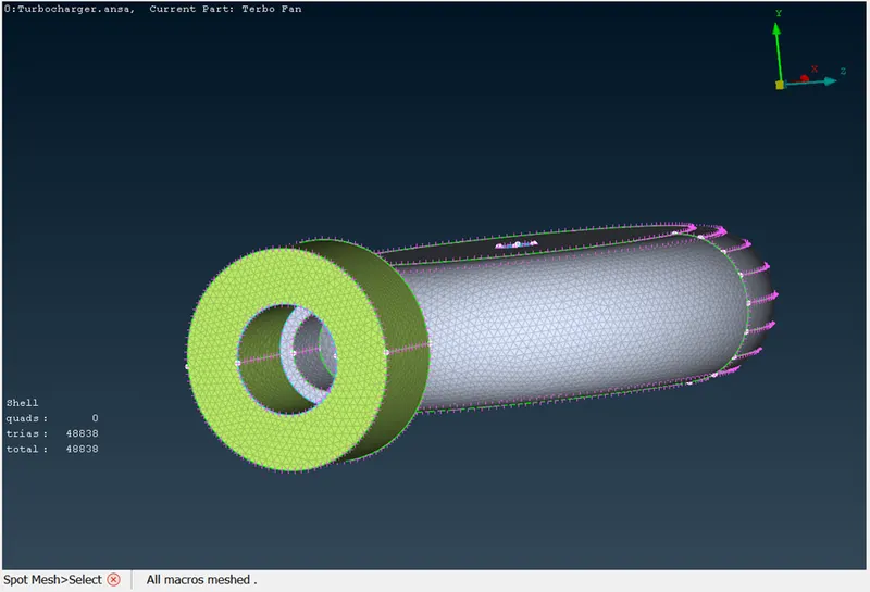
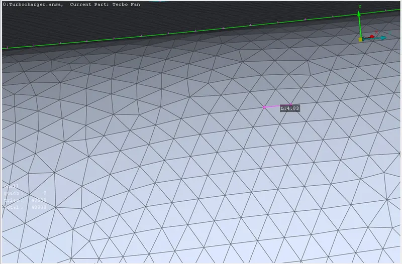
Bottm Casing Inlet and Outlet
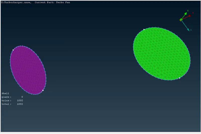
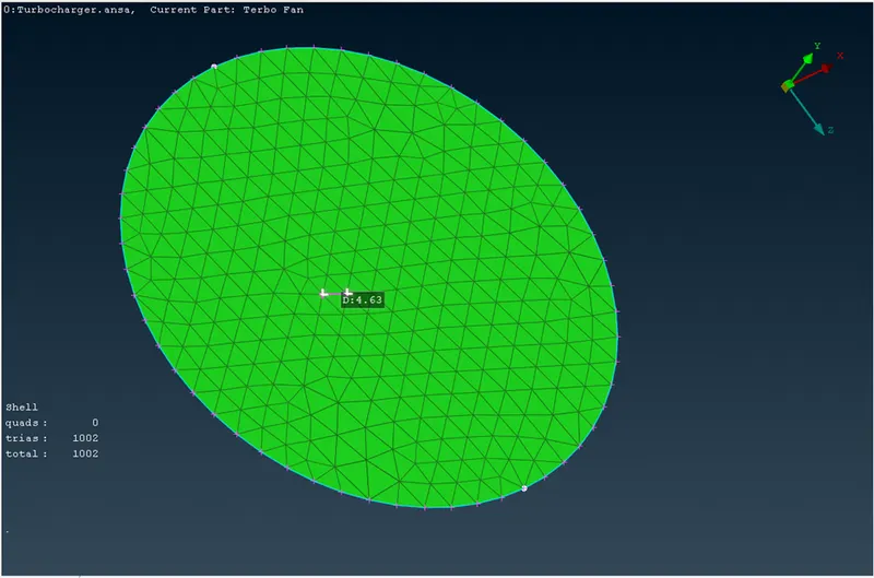
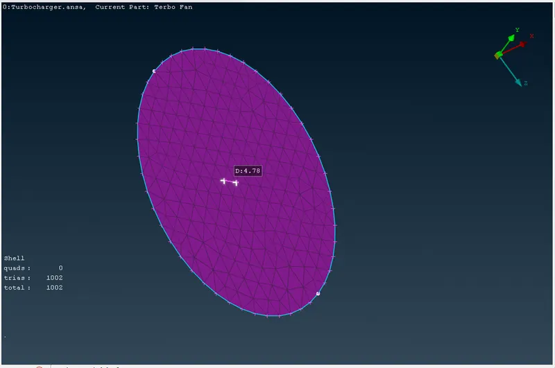
IMPELLER-2 mm
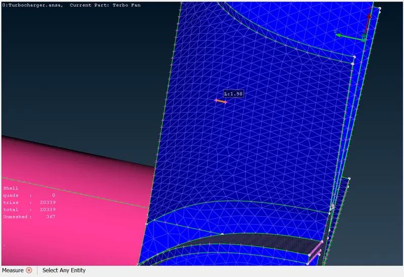
BLADE STAGE 1 AND BLADE STAGE 2-1mm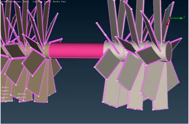
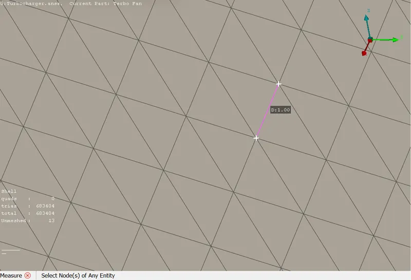
SHAFT ROTOR-1mm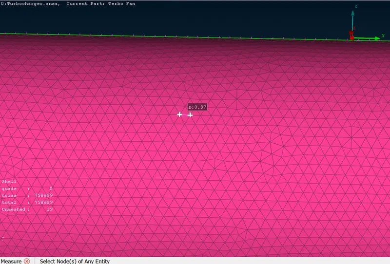
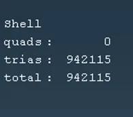
---------------------------------------------------------------------------------PREREQUISITE FOR VOLUMETRIC MESH
CORRECT SURFACE MECHING DONE
---------------------------------------------------------------------------------
6.TO DO VOLUME MESH
- Switch to volume mesh
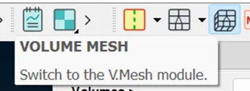
- Detect the volumes using DEFINE command.
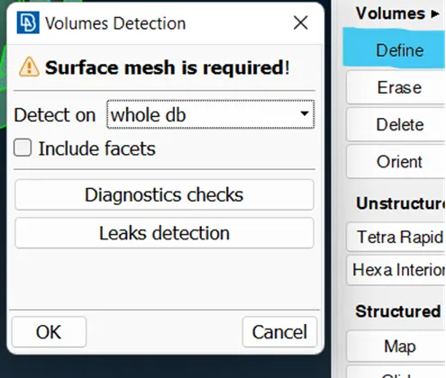
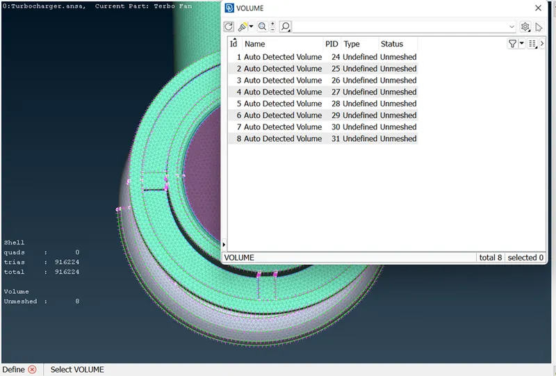
- TO delete the volumes that are not required
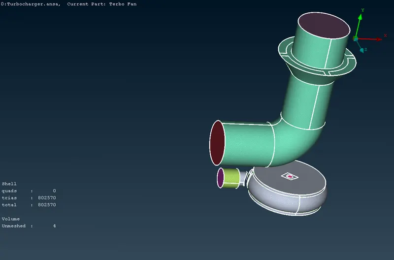
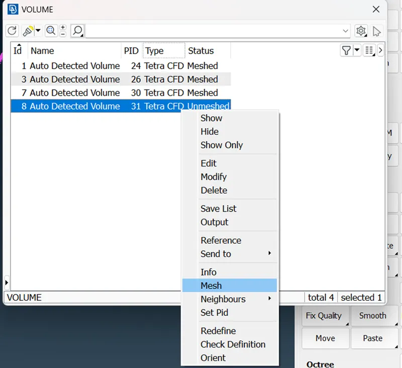
- TO MESH THE DEFINED VOLUMES
AS we are doing this mesh for cfd, cfd tetra(tetrahedral) elements are selected
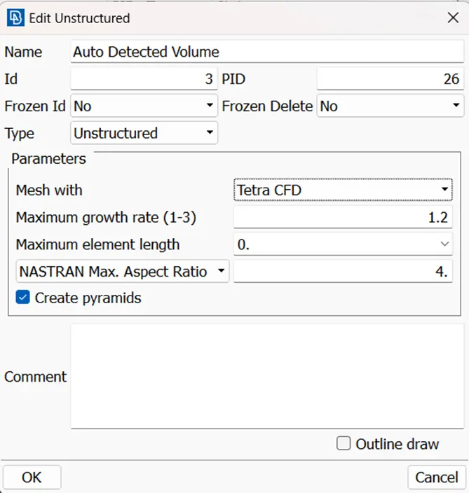
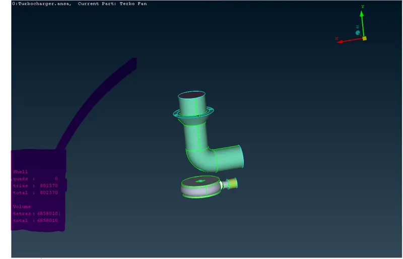
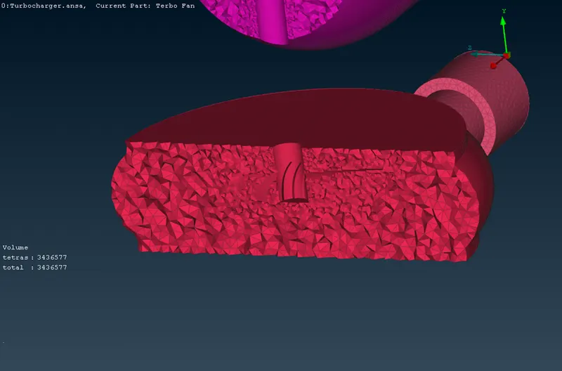
VOLUMETRIC MESH AND SURFACE MESH IS PERFORME DON THE GIVEN GEOMETRY.
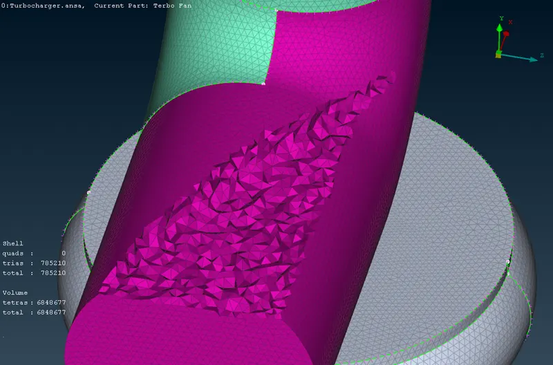
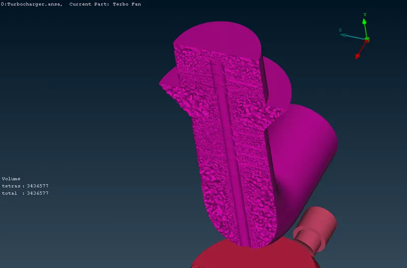
VOLUMETRIC MESH IS SEEN BELOW
CONCLUSION
VOLUMETRIC AND SURFACE MESH IS PERFORMED SUCCESSFULLY
WHEREEVER THERE ARE TWO DIFFERENT MESH LENGTH , A TRANSITION OF DISTANCE BETWEEN TWO NODES IS SEEN (ESPECIALLY AT THE BORDERS)
link for the zip file
https://drive.google.com/file/d/1PBbb9qCI5xl6qRgk0ZH3V04hK7GC79uV/view?usp=sharing