Week 3 Challenge : CFD meshing on Turbocharger
Aim : CFD meshing on TURBOCHARGER.
Objective : check for the geometrical errors to make appropriate volumes. Create and assign PIDs as shown in the video. Perform surface mesh with the given target lengths as per PIDs.
- Blade stage-1 = 1 mm
- Blade stage-2 = 1 mm
- Impeller = 2 mm
- Shaft rotor = 1 mm
- Turbo casing = 5 mm
- Compressor casing = 5 mm
- Inlet casing cover = 5 mm
Theory :
surface meshing : A surface meshing method based on a meshing-and-synchronizing strategy is proposed, which tackles the mesh generation of sliver surfaces and the cleanup of misaligned assemblies by means of mesh alignment. The mesh generation is performed in a hierarchical manner with curves and surfaces being meshed in sequence.
Three-noded trias, four-noded quads,six-noded trias, and eight-noded quads are some of the types of elements .
Volume meshing : Volume mesh or "solid meshing" uses three-dimensional elements to represent fully 3D objects, such as solid parts or sheets of material that have enough thickness and surface variety that solid meshing makes more sense than 2D shell meshing. 3D Elements Supported 3D elements.
One application of volumetric meshes is in "finite element analysis", which may use regular or irregular volumetric meshes to compute internal stresses and forces in an object throughout the entire volume of the object .
Procedure :
steps to create volumetric mesh are shown below
- Geometric import and check
- Setting up properties using set PID command
- Geometric clean up
- Meshing
- Surface meshing
- Volumetric meshing
- measuring the length
Geometric import and check :
First step is to import the geometry into the ANSA by going to FILE>OPEN>IMPORT.
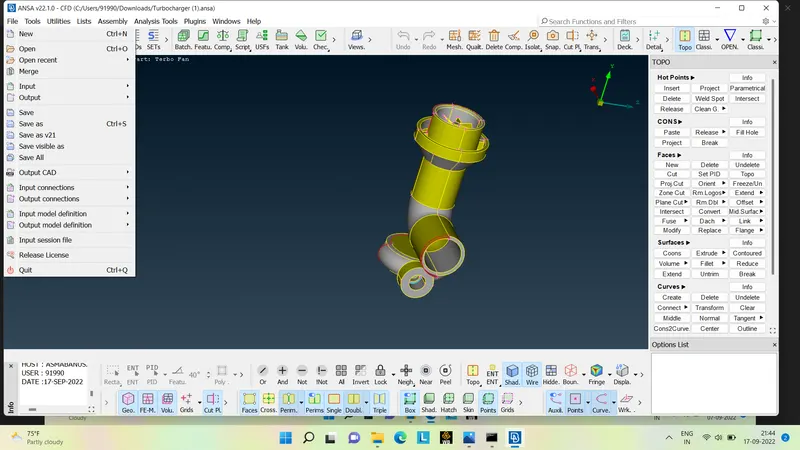
Checking geometry : For geometric check we have to go to TOOLS>CHECK>GEOMETRY.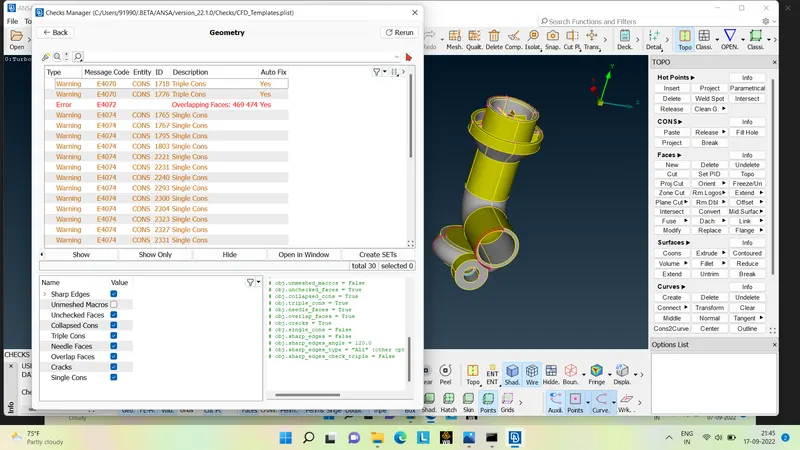
As we can see above we have many single , triple cons and some overlap surfaces which has to be resolved befor going or doing the mesh
Geometric clean up :
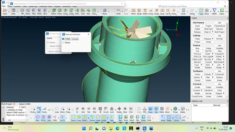
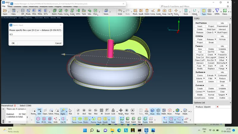
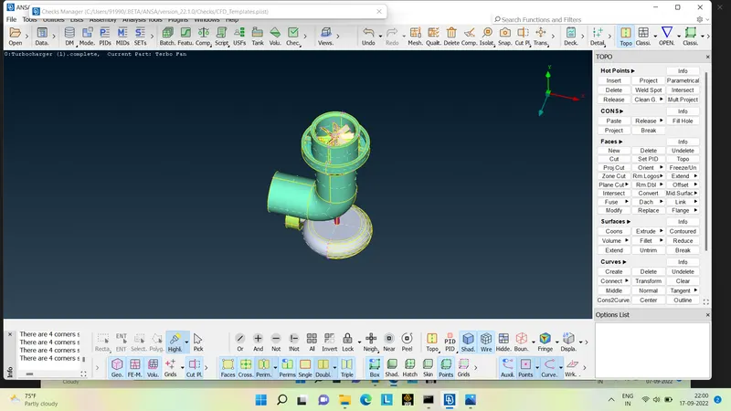
We have to clean the geometry by removing the extra surface , hot points 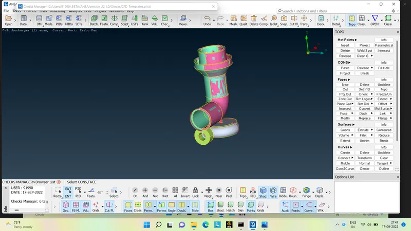
- we can see the glitching present in above given model . here pink surface is overlapping the green surface , these overlap surface has to be delete by TOPO>DELETE .
- Now fill up the surfaces and start to convert single and triplecons into double cons .
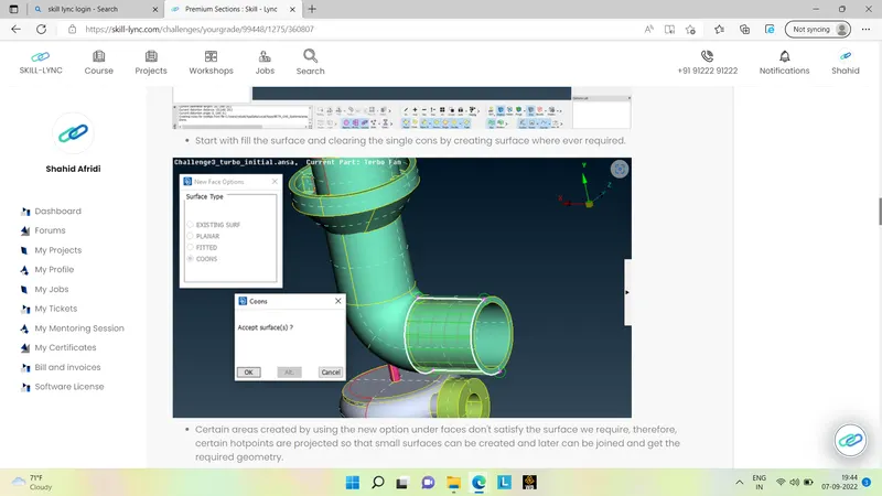
Setting the properties using set PID commands :
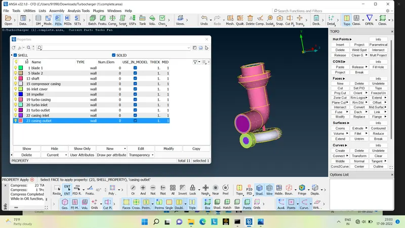
For setting the properties we have to turn on the crossedge in order to give the properties. After that we have to go to properties , then we have to create the new shells and we have to the naming to it as shown below
- blade 1
- blade 2
- impeller
- turbocasing
- turbo inlet
- turbo outlet.
- compressor casig
- compressor inlet
- compressor oulet
- inlet cover
- shaft
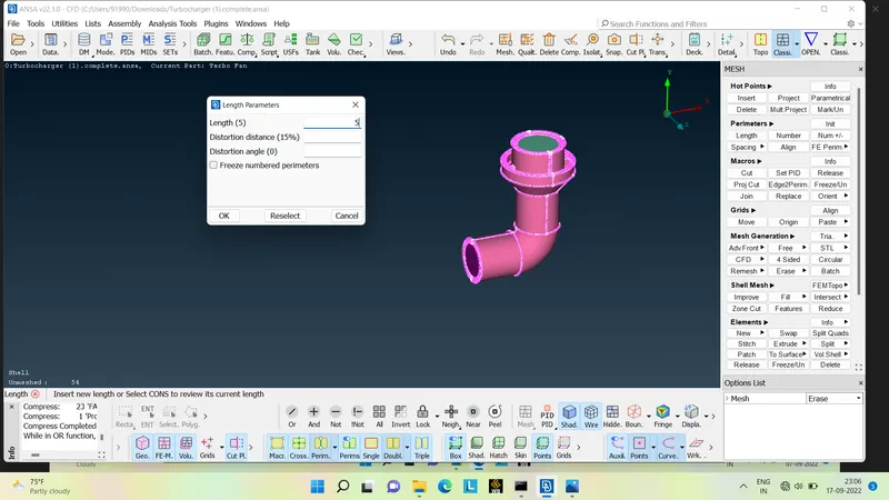
Meshing :After cleaning the geometry wwe have to do the mesh by going into MESH>LENGTH>PARAMETRIC>MACRONS. After that set up the mesh elements by going to MESH PARAMETERS>TARGET LENGTH>ELEMENT TYPE >SPOT MESH >VISIBLE .
Meshing the compressor casing , casing inlet and outlet,turbocasing , tubo inlet and outlet , inlet cover by 5mm length as shown below
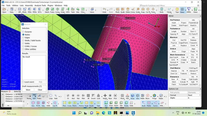
Now mesh the blade 01,blade 2,and the shaft with 1mm lenght and impeller with 2mm lenght .
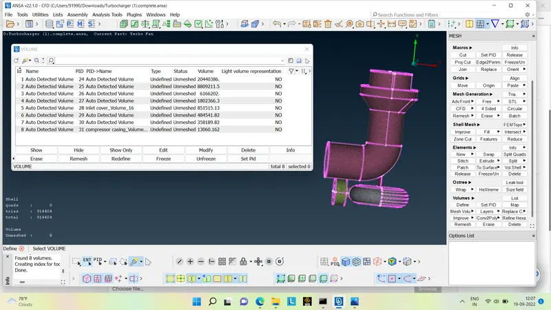
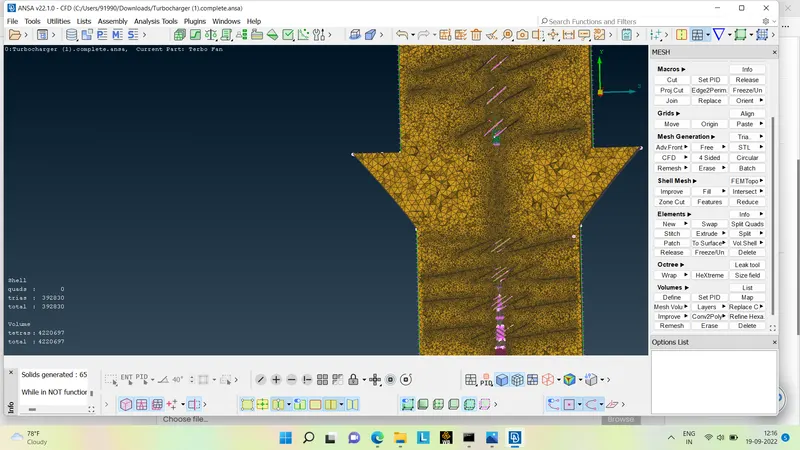
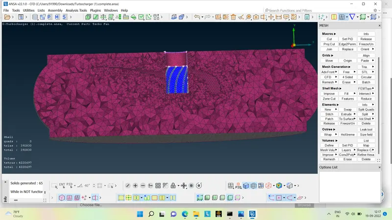
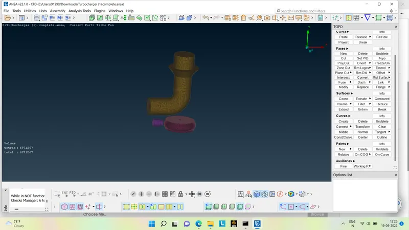
Volume mesh : For generating a volumetric mesh we have to go to VOLUME>DEFINE>WHOLE DATABASE >OK .
It will detect the 8 volumes in which we need only four volummes from where the fluid will flow and the thickness of the components will have to delete .
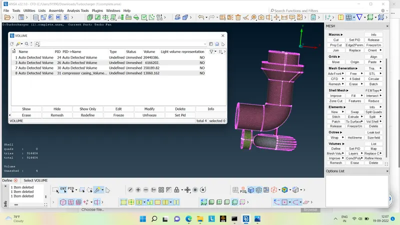
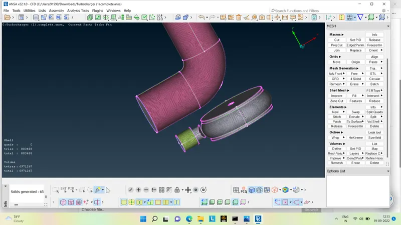
Once selecting the required volumes double click on it , select Tetra CFD and remesh it .
Conclusion :
- Realize the volume mesh of the turbocharger model .
- Different mesh length sizes tends to cause erroors in the contract areas of two different mesh length areas to specify a mesh area to avoid mesh deletion .
- volume meshes can only be achieved after surface mesh has been successfully created .other wise tje geometry can cause the errors in the volumetric mesh .
- Duplicate face can be delete by universal delete option .
- We can use various tools such as Cons-project ,Topo,Release and Fine tools to organize our geometry .for removing the single cons and triple cons .
- The correct geometric clean up and surface mesh must be used for the volume mesh to be successful.
https://drive.google.com/file/d/1Z7Sjex36ifMnewywCLRriHoAPLsodYBx/view?usp=sharing