Week 3 Challenge : CFD meshing on Turbocharger
https://drive.google.com/file/d/1bDfL0m5ZNSfFs064Wn3bt_5qr98W48FQ/view?usp=sharing
Aim: To create and assign PIDs as shown. Perform surface mesh with the given target lengths as per PIDs.
- Blade stage-1 = 1 mm
- Blade stage-2 = 1 mm
- Impeller = 2 mm
- Shaft rotor = 1 mm
- Turbo casing = 5 mm
- Compressor casing = 5 mm
- Inlet casing cover = 5 mm
Procedure:
Geometry cleanup:
1.Check the overlapping by turning on PID MODE and delete the overlapped structure by selecting it.
2.We cannot able to create coons by selecting loop option. So new Hotpoint is created to create the whole missing structure.
3.This structure is intersected with the layer so by using intersection option we have to bisect it and delete the excess portion.
4.Turbo compressor is in semi spherical cylinder shape so there is no exact option to create the structure. We have to create hotspot accordingly with respective direction using parametrical option under Hotpoint.
5.The overall structure is with open inlet and outlet. For meshing, surface should not be open so create closing structure for inlet and outlet of the turbo casing, compressor casing and fan passage.
6.Then check the geometry using check>geometry option identify the triple and single cons.
7.Throughout shaft area triple con is present. Inbetween plate surface are deleted then single con created. By using topo option single cons is corrected.
8.In the above area structure is overlapped so we have to create the stage 2 blade in single shaft so by projecting shaft in another shaft we are cutted the overlapped surfaces then delete the unwanted structure.
9.Name the PIDS accordingly such as fan stage 1, fan stage 2, impeller, turbo casing, compressor casing, inlet turbo casing, outlet turbo casing, inlet compressor casing, outlet compressor casing, casing cover and shaft.
Meshing:
SURFACE MESH:
Step 1:length>perimeter and macro
Step 2:mesh generation>spot mesh>visible or select.
Create mesh for different length for different PID accordingly.
By following measurement
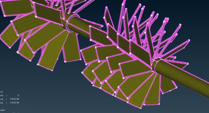
- Blade stage-1 = 1 mm
- Blade stage-2 = 1 mm
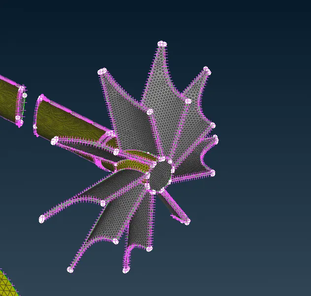
- Impeller = 2 mm
- Shaft rotor = 1 mm
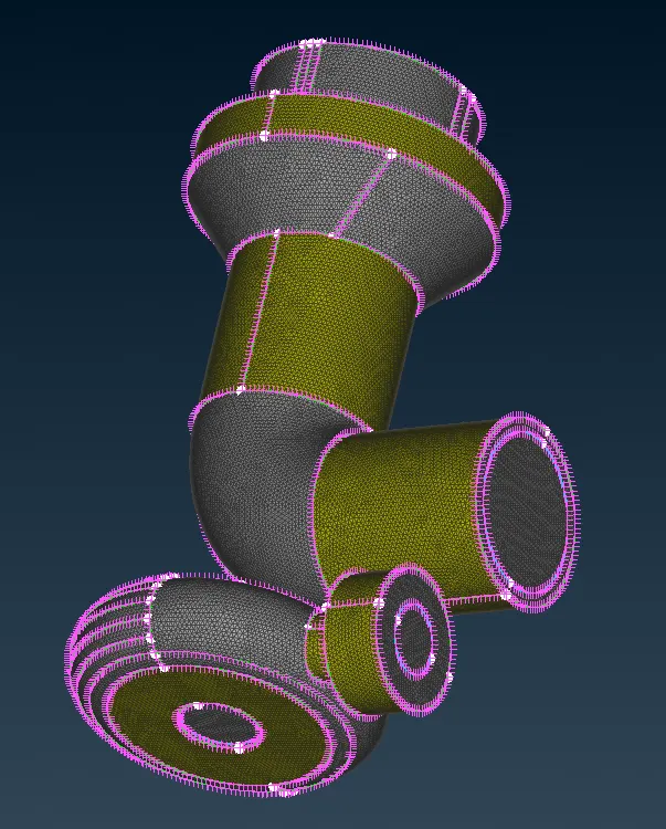
- Turbo casing = 5 mm
- Compressor casing = 5 mm
- Inlet casing cover = 5 mm
By creating 2 different length the intersection area mesh got erased so to rectify that in macro option the ranging will differ so we should not give any values for under length>macro option.
VOLUMETRIC MESH:
Step 1:Volumetric mesh>define
Step 2: list of closed volume label will appear.
Step 3: in the seprate the fluid flow alone. Delete the outer area and parts of the figure.
Step 4: double click the unmeshed, new dialogue box will appear.
Step 5: Declare the mesh type and create the volumetric mesh for all part.
Step 6:To check the mesh use cut plane option.
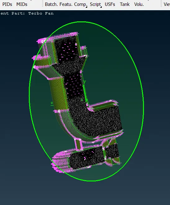
Cut plane>new>default xy, click the cursor on the structure
Step 7:New dialogue box will appear. In that ctreate new surface and save.
Project outcome:
Used to learn the following things
- Usage of intersection option.
- Volumetric mesh and types
- Using cut plane option.
RESULT:
TOPO CLEAN UP:
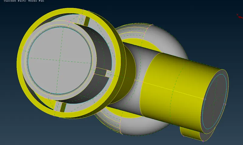
BLADE AND SHAFT WITH 1MM:
IMPELLER WITH 2MM:
TURBO CASING , CASING COVER AND COMPRESSOR CASING WITH 5MM:
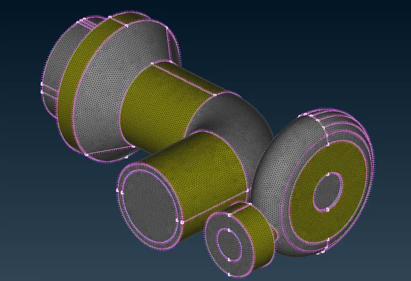
SURFACE MESSHING:
VOLUMETRIC MESHING:
Conclusion:
The surface and voumetric mesh is done with given mesh length.
DRIVE LINK: https://drive.google.com/file/d/1bDfL0m5ZNSfFs064Wn3bt_5qr98W48FQ/view?usp=sharing