Week 3 Challenge : CFD meshing on Turbocharger
challenge 3- CFD MESHING OF TURBO CHARGER
AIM- for week 3 challenge we are given the geometry of a turbocharger for this challenge we have to clear the geometrical errors to generate appropriate volumes and assign the PIDs to perticular body and perform surface mesh with given target lengths
1.blade stage 1=1mm
2.blade stage 2=1mm
3.impeller=2mm
4.shaft rotor=1mm
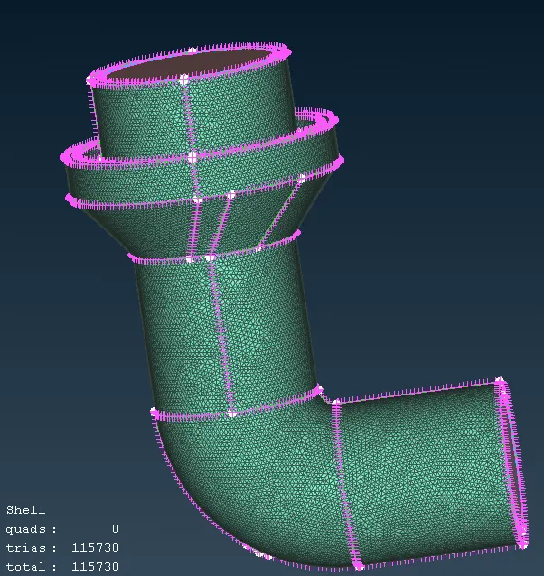
5.turbo casing=5mm
6.compressor casing=5mm
7.inlet casing cover=5mm
PROCEDURE-
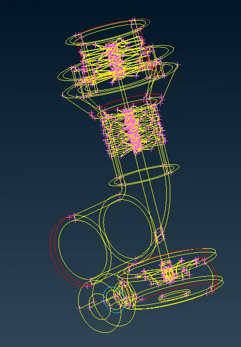
1.as to start this challenge we have to download the geometry which is geometry of turbocharger and open that file in ansa as we open the geometry initially the geometry will be in wireframe mode like shown in below image here we can see the errors like red cons,triple cons we have to clear those error
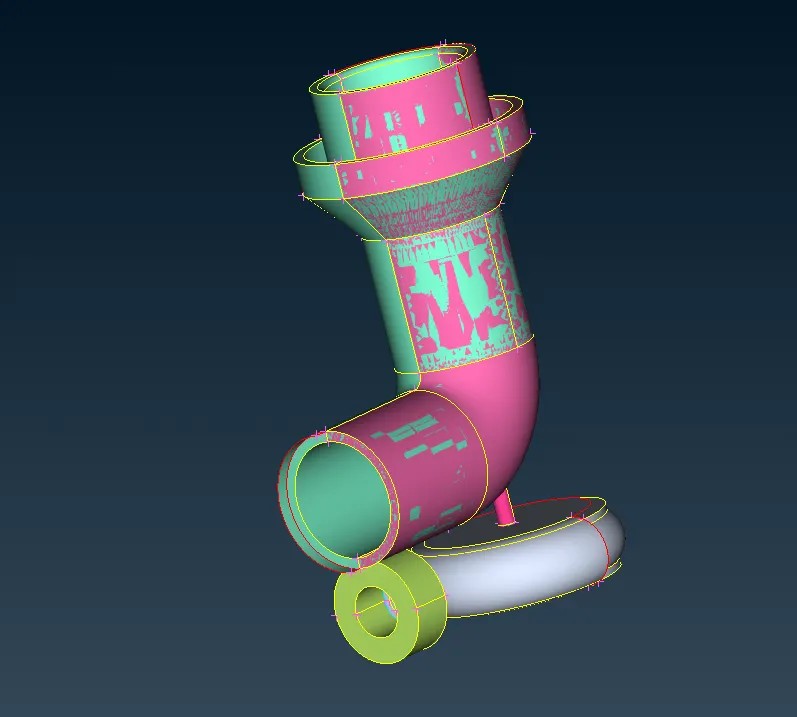
2.for starting the cleanup first we have to switch from wireframe mode to shadow mode and enable PID the model will be shown like this after switching. as you can see we can see some overlapping surfaces are showing we can see some glitching
3.open the PID manager from PIDmanager we can hide or unhide the surfaces to get a clear vision of the overlapping surfaces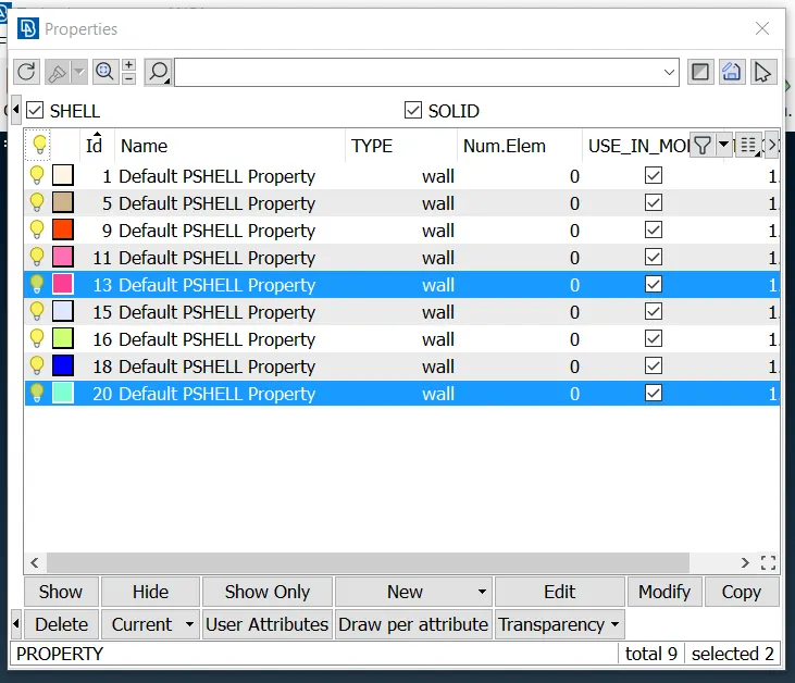
4.through the PID manager as we hide the necessary pid we'll try to delete the unnecessary or unwanted pid we can do thid using universal delete option there is another way where we have to delete the surfaces by selecting them one by one which will be time consuming for the larger geometry as you can see we have selected unwanted PID
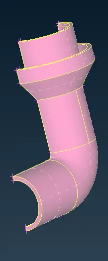
5.after deleting the unwanted pid or we can say overlapping surface our geometry will look like this
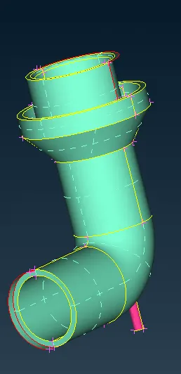
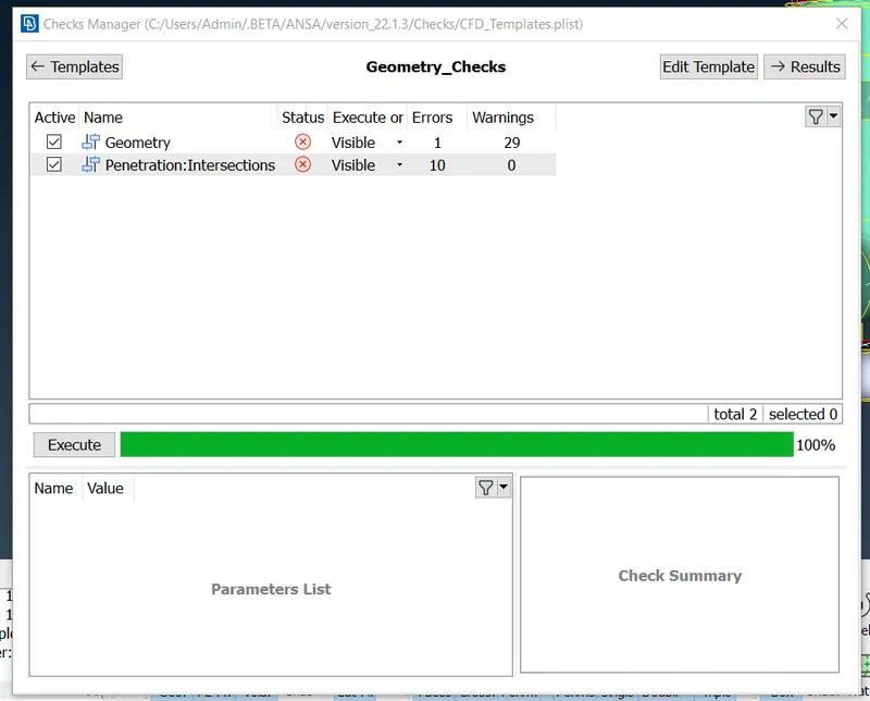
6.now we have to perform the geonetry chechkup to see how many errors we encountered or we can say how many errors are present in the geometry
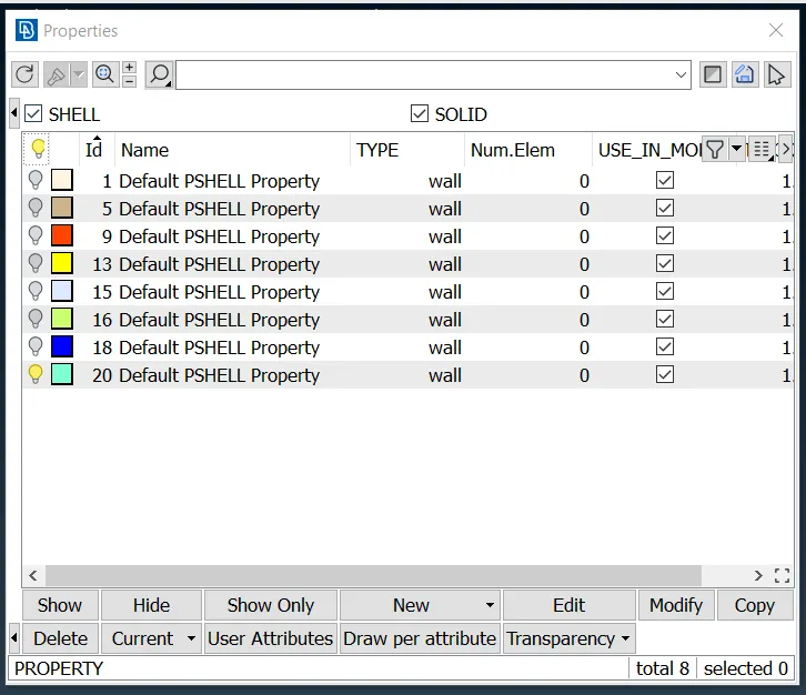
7.now we have to compress the deleted pid to remove it from pid manager as we deleted that unwanted pid we can use the compress option so the pid will be deleted automatically we can see that in pid manger as well

8.now there is unwanted surface we have delete that surface and create a new perfect surface to eliminate a error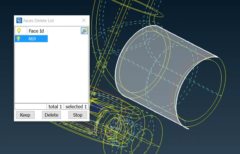
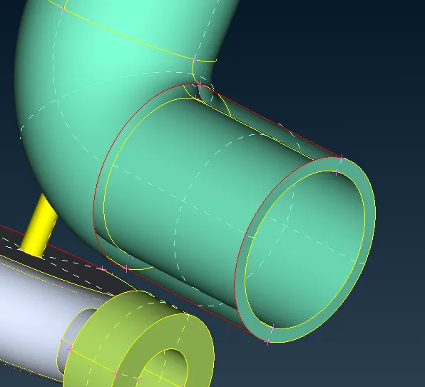
9.as we have deleted the surface it'll show like this here we have to create new surface
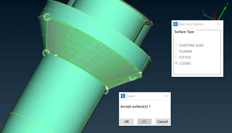
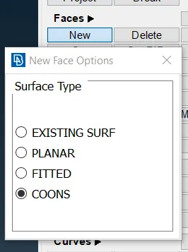
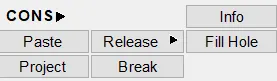
10.the new surface is created through new option in that option we have to choose coons enble the loop so we can select all the cons by one click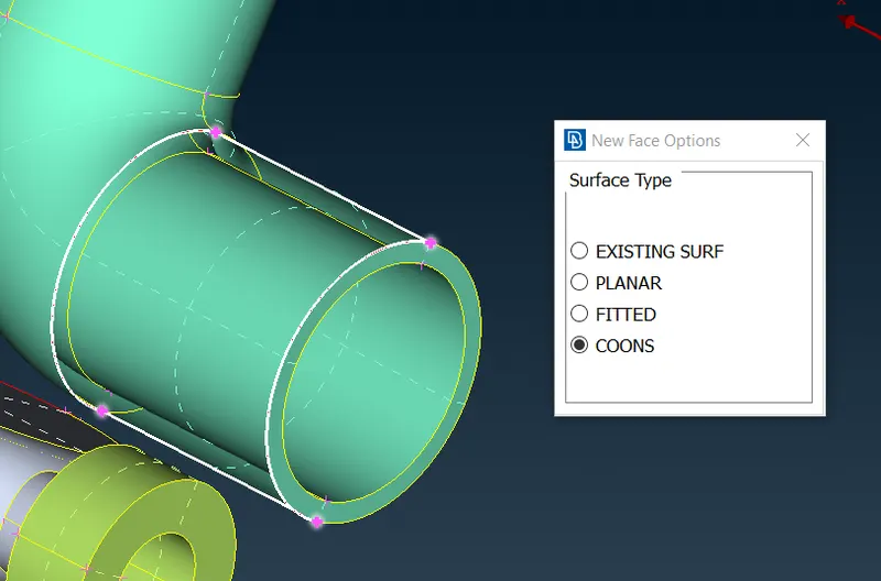
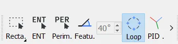
11.as we look at the upper part we can see an uneven surface we have to make it even by using intersection option
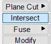
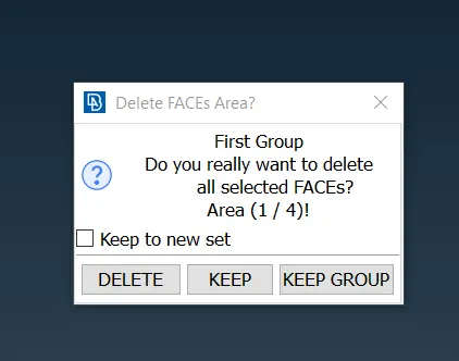
12.in this intersection option we have select the two surfaces after selecting the two surfaces a pop up will occure asking whether to keep the surface or delete it we have delete the unwanted surface and keep the necessary surfaces
13.after this boundry will be generated but this boundry is not straight or we can say perfect so we have to make a cut after deleting the below surface
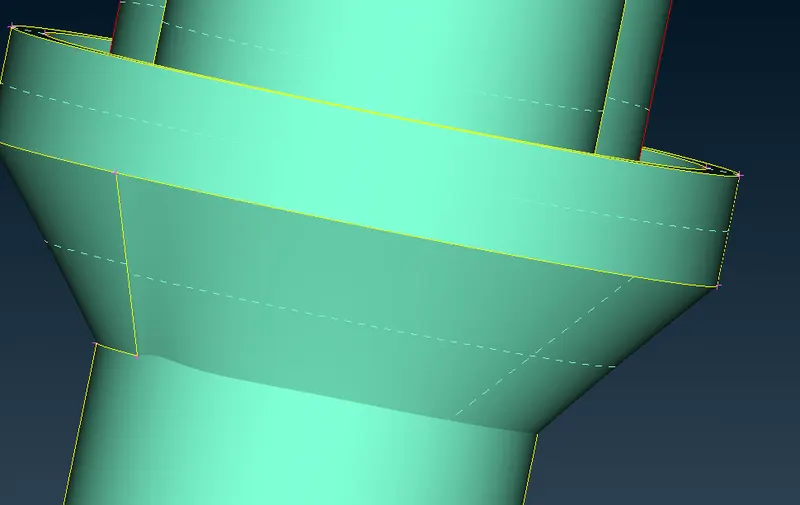

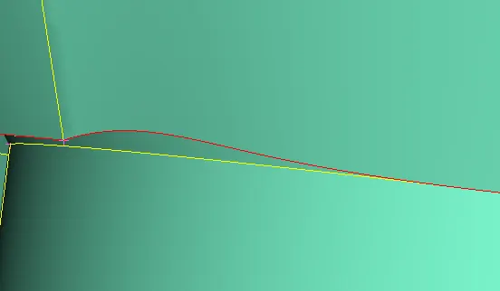
14.after this we have to make new surface using coons and loop option
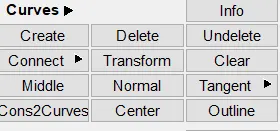
15.now we are learning a new tool to be used for creating curves it is in topo-curves-transform in this we have to select the con and direction of curve we can see that how we performed the transform option in following image as well
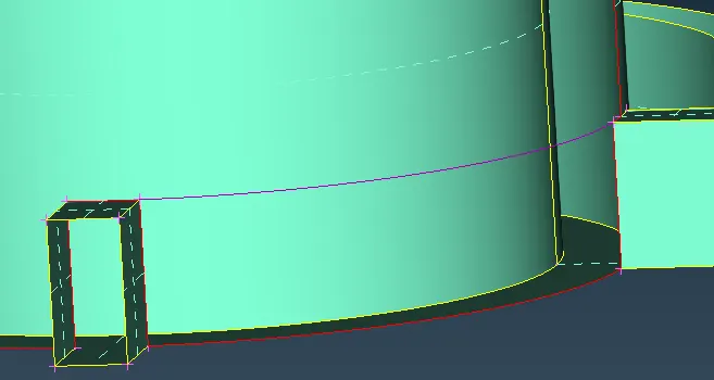
16.after the curve is generated make a new surface using coons then enabling loop option and using coons or fill hole we can generate the remaining face
 /
/
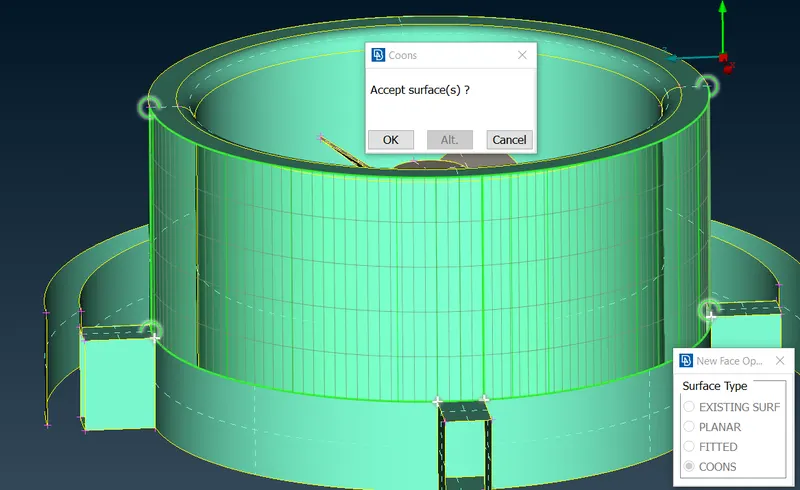
17.we can delete the previously generated cons for generating curve surface
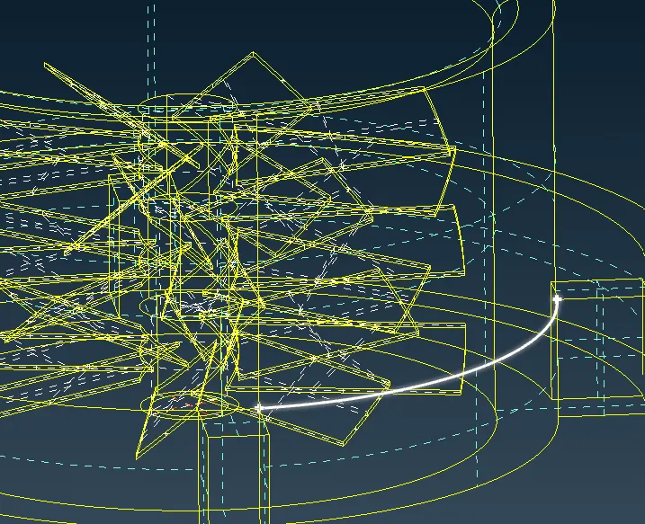
18.as we have generated new faces/surfaces we have to change the resolution as well for smoother smoother surface(i.e 1mm)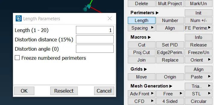
19.now we are learning new tool transform after clicking transform we have to select copy then its asking entitiesor nodes as shown below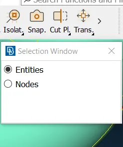
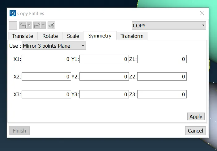
20.after clicking the desired entity a pop up will show like below in that we have to select the symmetry and then mirror 3 points plane this will endup like as shown below this will mirror the selected curve surface
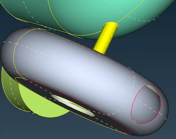
21.we can close the open hole using fill hole option
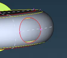
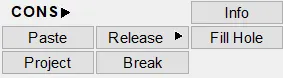
22. as we can see there are some red cons present we can eliminate them using topo option select the topo option and doa box click over a red conc region
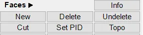
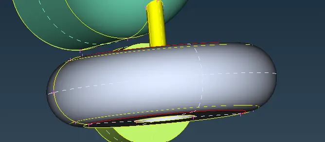
23.after topo cleanup the red cons will be eliminated like below
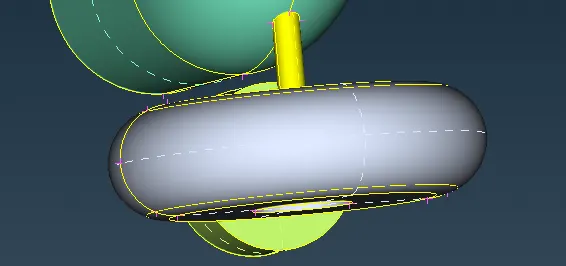
24.now as we run the geometry check we can see intersection error are showing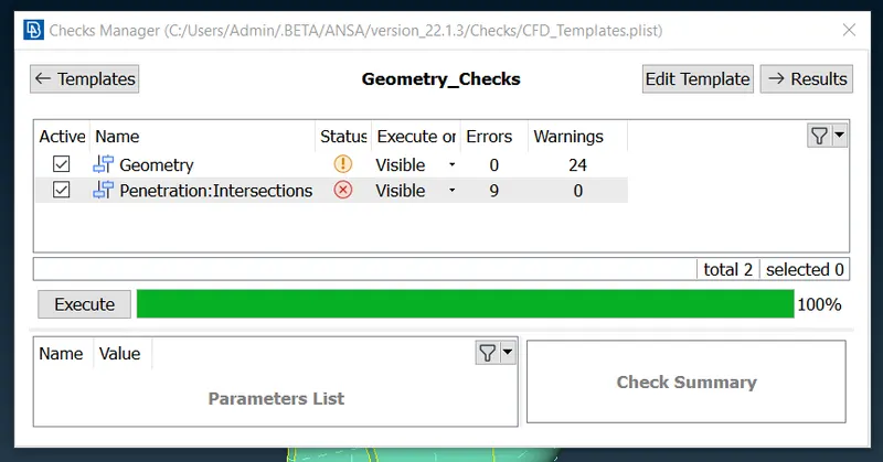
25.as we have to eliminate the intersection error we hide the other pid and only fins will be shown and will do topo cleanup after locking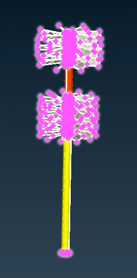
26.as we see the overlapping surfaceon shaft we'll delete the extra surface using delete option delete all the extra surface/overlapping surfaces using delete option
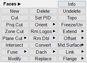
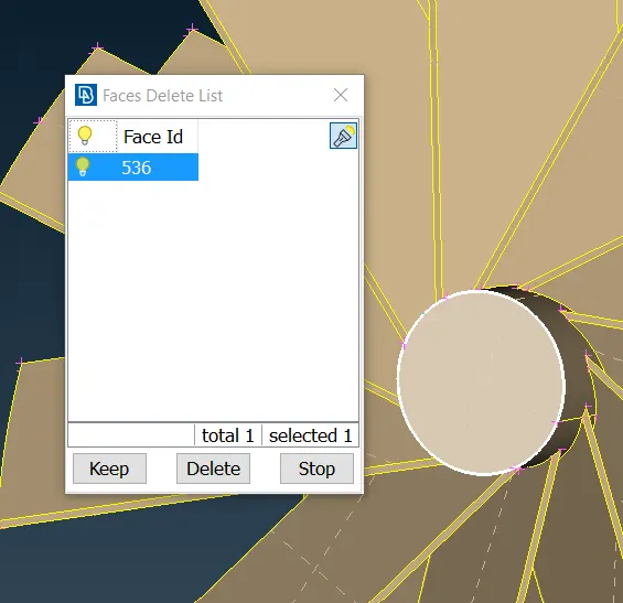
27.now for an intersection error we have delete the surface and make a new surface and assign it to the existing pid
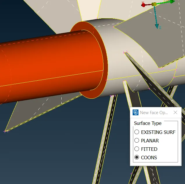
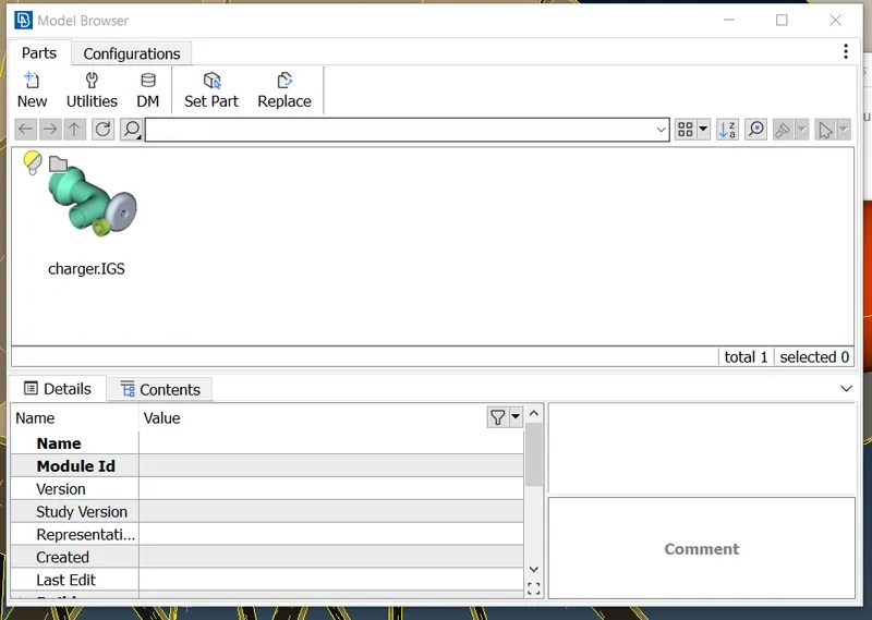
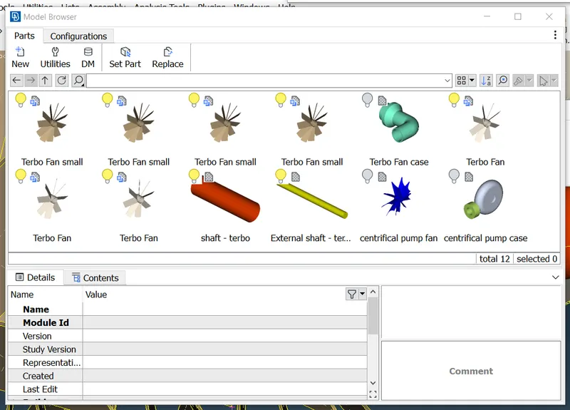
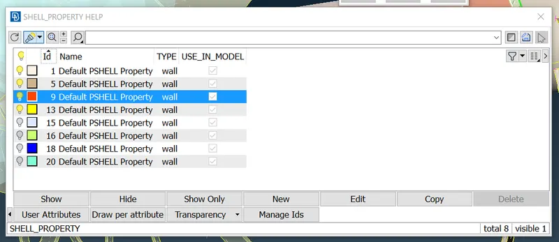
28.after cleaning all the intersection error we run the geometry check the results are as below and total geometry results are also shown below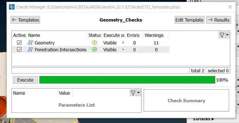
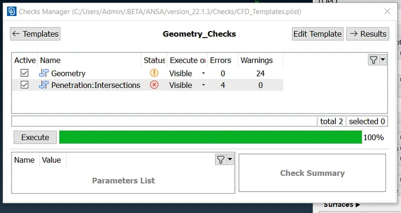
29.now for bottom intersection we have to clean those overlapping surfaces we will delete the overlapping surfaces using delete option then selecting perticular cross hatches
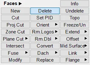
30.there will be two red cons generated by our previous surface deleting action for this we have to use project option and make them triple con and create a new surfacethen delete those new surface so we can eliminate the red cons
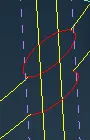
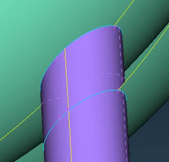
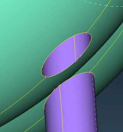
31.again we are going to encounter same intersection error like above one so we have to repeat the same procedure like above we have to delete the overlapping surface it'll form red cons then we have project those and then later delete the new surface generatedso the red cons will be eliminated
32.for next intersection error we have to delete the the suface as shown in the image because there are two surfaces overlapping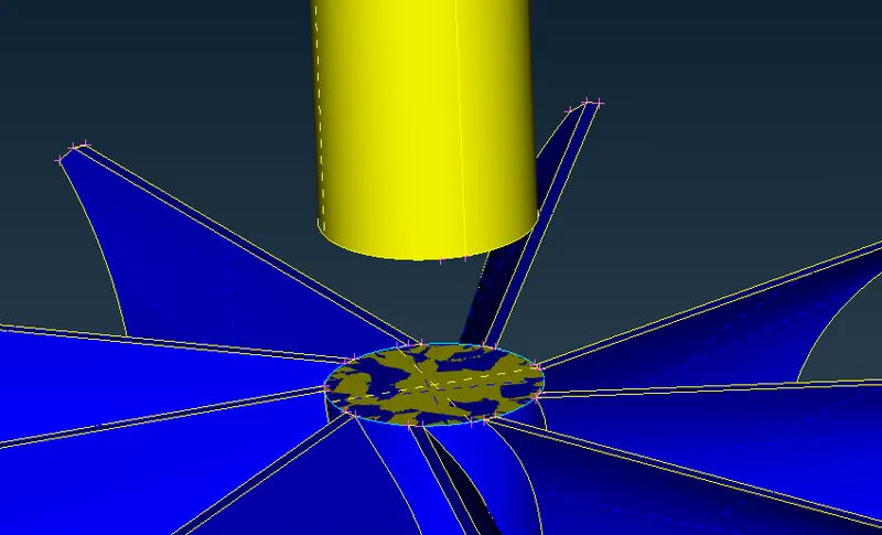
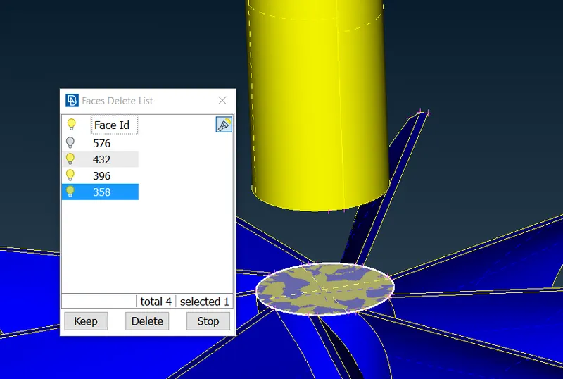
33.after deleting this surface we will encounter with triple con to eliminate this triple con we have to use the cut option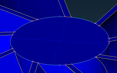
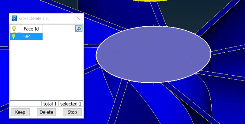
34.after deleting the surface the geometry will look like this and red cons will appear on edges we can eliminate those by doing topo cleanup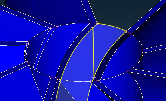
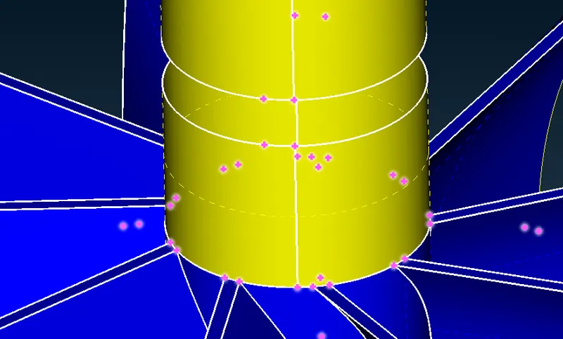
35.red cons elimination will look like this we can see it below
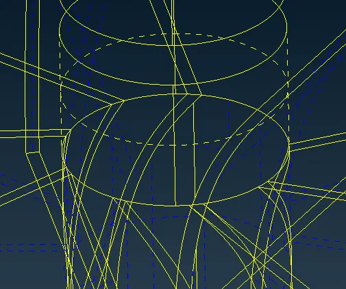
36.now as we do geometry check we can see tere is one intersection error is showing
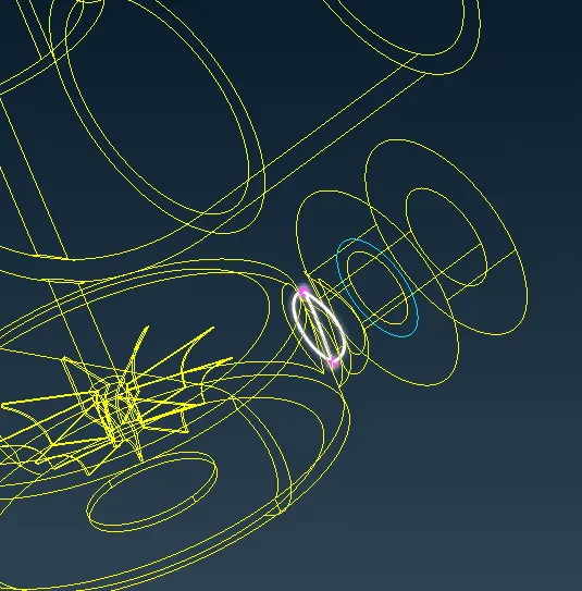
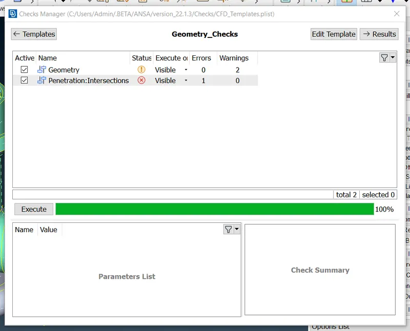
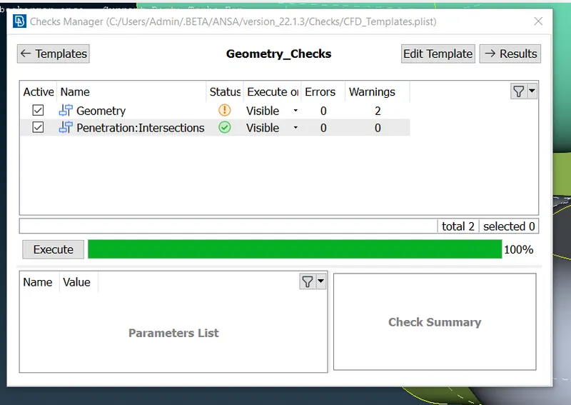
37.now for last intersection error we have to delete that part to eliminate that error as we delete that part there is no intersection error in geometry check manager
38.now we have to start surface meshing so we have to make the geometry waterproof by closing all the openings to perform volumetric meshing
39.as we mentioned above we have to close all the openings we will do that using fitted option and we will close all the openings to make the body waterproof and it'll look like this
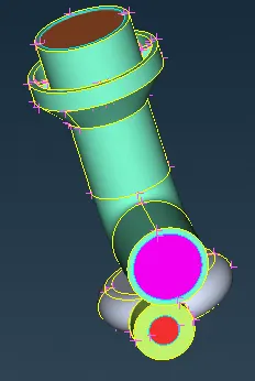
40.now before starting meshing we have to assign the PIDs to the all part and make the changes according to it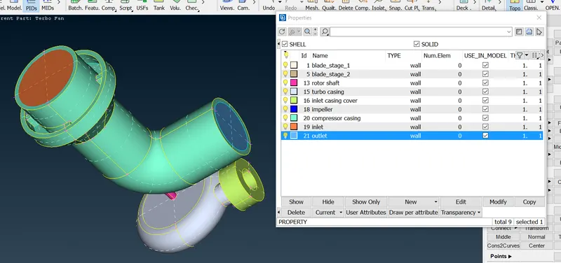
41.now we have to start the surface meshing process as per given target lengths as per challengefirst we will start with 5mm target length this 5mm meshing length will be applied to the turbo casing compresser casing and inlet casing cover after meshing the parts will be look like this
42.next part is impeller casing for this given target length is 2mm after meshing the impeller will look like this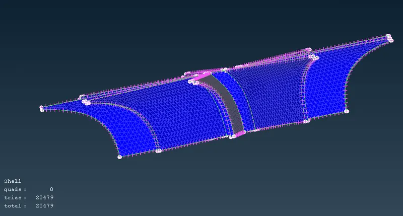
43.now the remaing parts like blade stage 1 & 2 and rotor shaft are given target length of 1mm so we will do as per challenge
44.after doing meshing of all the parts still we encountered with problem there are some parts which remains unmeshed because of confusin at the boundry's to which meshing length should be applied as two surfaces are sahring same boundry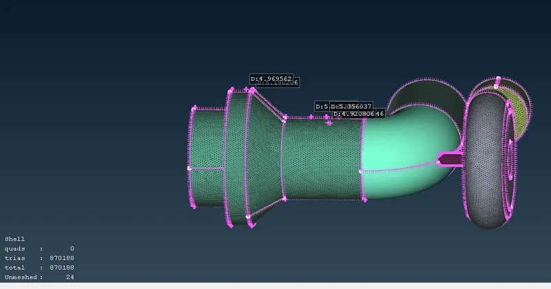
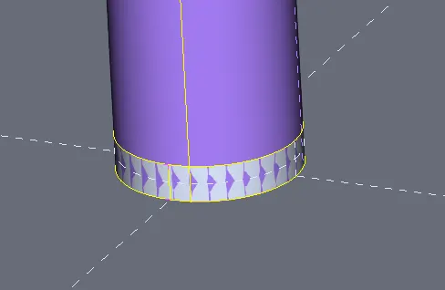
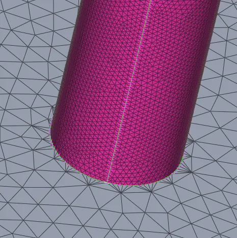
45.as we know we can eliminate this error by using free mesh after using free mesh we can at boundry there some uniqe meshing patterns are generated like shown in the picture there are other ways we can eliminate this error free mesh is time saving among them
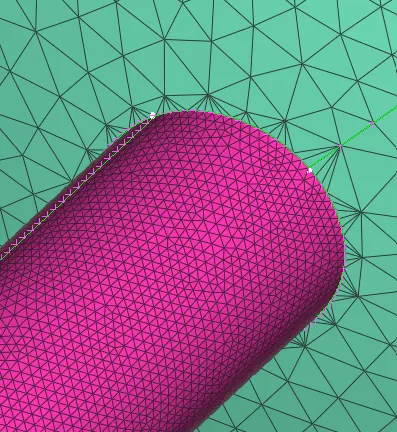
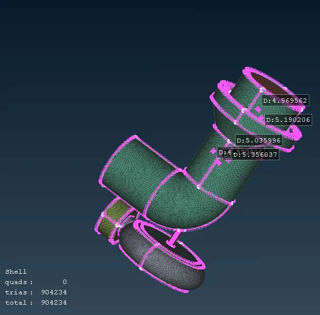
46.now we can will start the volumetric meshing in mesh deck there is option of volumetric meshing remeber for volumetric mesh we have to make sure that the geometry is full surface meshed and its a close body there is no opening as you can see there is no unmeshed surface is present
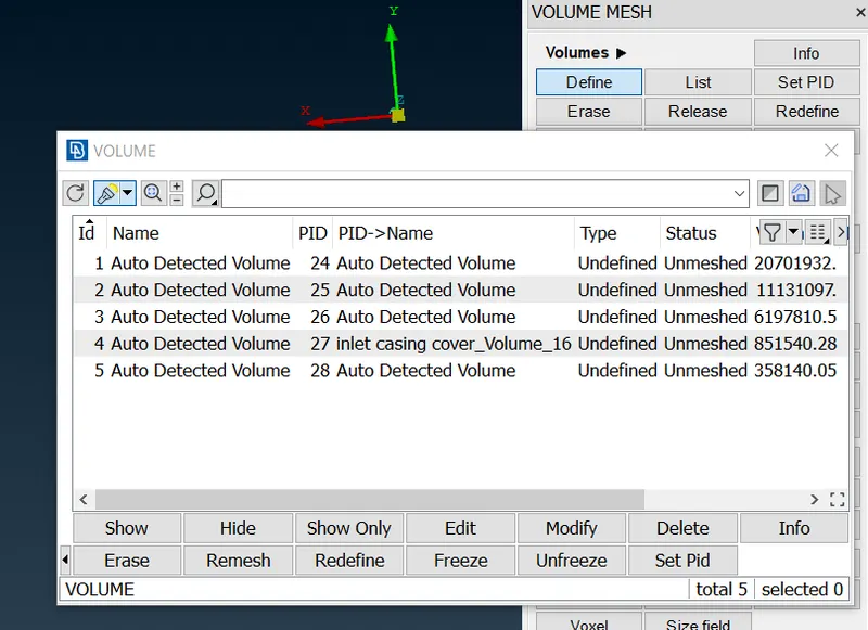
47.now we can start the volumetric meshing in this we have to select define and then select whole database while selecting whole database ansa will ask if the body is surface meshed afte this a pop up will occure showing all the volumes needs to be meshed(volumetric mesh) here we can keep or delete the volumes according to the our CFD analysis
48.after deleting the unncessary volumes and remeshing the remaing volumesin tetra cfd the volumes are meshed like this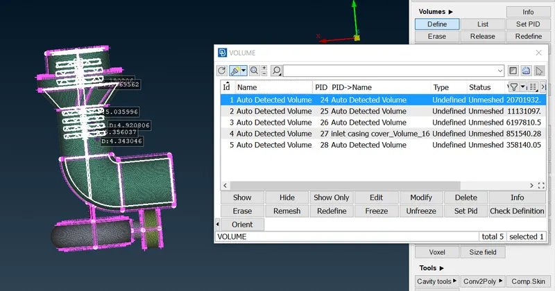
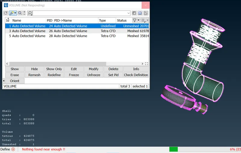
49.now using not option we can see the meshed surface it'll appear like this we can see in different angle using nit option
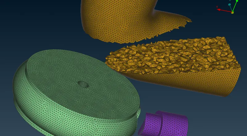
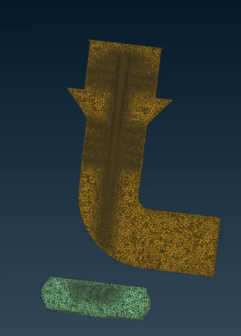
50.we can enble or disable the using the following options we can see geometry if we want or volumetric mesh as per our choice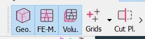
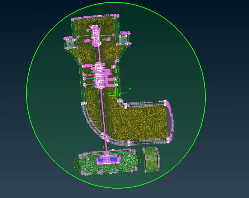
51.there is another option known as cut plane we can cut the geometry according to the any plane by using this option we do a plane cut for inspection in XY plane it appeared like this
LEARNING OUTCOME - IN THIS CHALLENGE WE GET TO LEARN HOW TO PERFORM VOLUMETRIC MESHING REQUIREMENTS TO PERFOEM A VOLUMETRIC MESHLIKE YOU NEED HAVE ALL GEOMETRY MUST BE SURFACE MESHED AND CLOSED ,HOW TO ELIMINATE INTERSECTION ERROR WE HAVE LEARNED SOME NEW TOOLS LIKE TRANSFORM ANY MANY MORE NEW OPTIONS LIKE FREE MESH HOW TO PERFORM FREE MESH
RESULT-AFTER CLEARING ALL THE ERRORS AND DOING THE SURFACE MESH WE HAVE DONE A SUCCESFUL VOLUMETRIC MESHAS YOU CAN SEE BELOW
CONCLUSION-WE CAN SAY ITS VERY IMPORTANT TO ELIMINATE ALL THE ERRORS AND CLOSING ALL THE OPENINGS IN RIGHT WAY AND YOU MUST PERFORM ALL SURFACE MESH BEFOE GOING FOR VOLUMETRIC MESH OR ELSE IF THER'S ANY SURFACE REMAaining we can not perform volumetric mesh
GOGGLE DRIVE LINK OD ANSA FILE-https://drive.google.com/file/d/17Xa5QsuojiH9h5xjH9Q7zeLsagEugvhl/view?usp=sharing