Week 3 Challenge : CFD meshing on Turbocharger
Week 3 Challenge : CFD meshing on Turbocharger:-
Aim:-
(i) To check for the geometrical errors and perform Topology cleanup accordingly,and to perform surface mesh with the given target lengths as per PIDs.
- Blade stage-1 = 1 mm
- Blade stage-2 = 1 mm
- Impeller = 2 mm
- Shaft rotor = 1 mm
- Turbo casing = 5 mm
- Compressor casing = 5 mm
- Inlet casing cover = 5 mm
(ii) To perform Volumetric mesh for the required volumes
Software Used:-
ANSA v22.1.0
Procedure:-
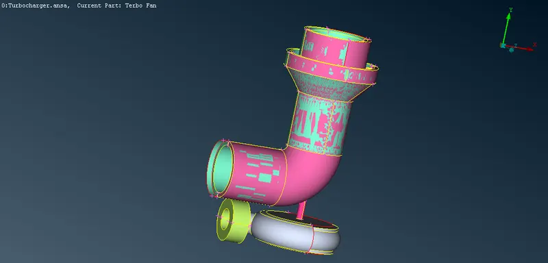
- First of all need to open the given model and then need to switch to PID mode to view the errors more effectively as shown in fig.
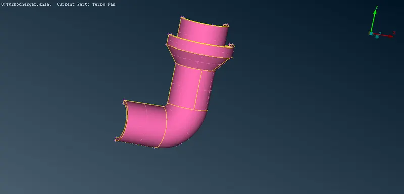
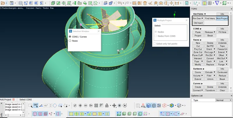
- Then need to delete the overlapping surfaces by seperating them and selecting them as shown as fig.
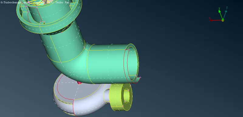
- After that need to delete the extra surfaces presented on the model by using delete and SURFACES>>NEW>>COONS options as shown in fig.
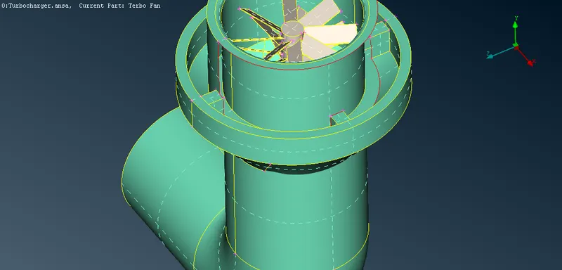
- After that need to fill the single CONS surfaces by using new surface option as shown in fig.
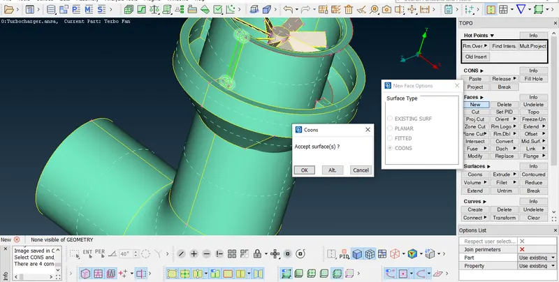
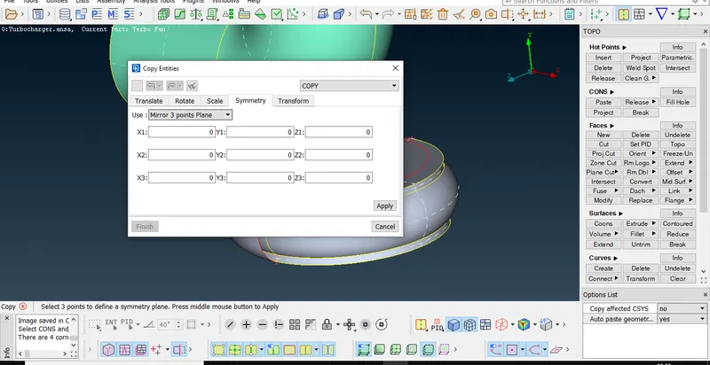
- After that need to create the surface to clear the singe CONS on Compressor casing by using TRANSFORMER>>COPY>>SYMMETRY>>AXIS 3 POINTS PLANE option as shown fig.
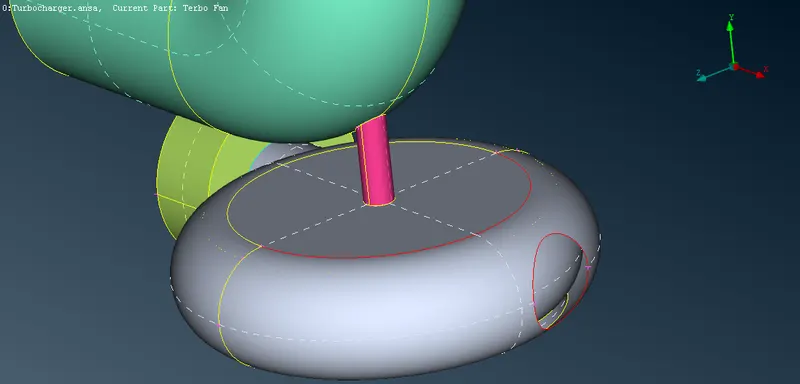
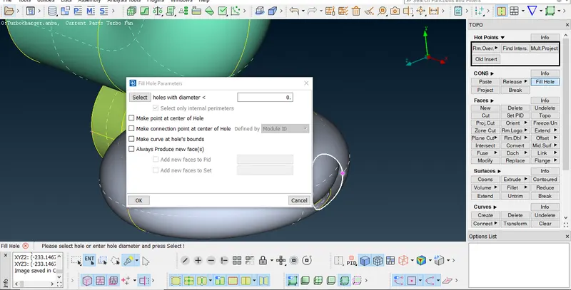
- After need to close the hole on the transformed surface by using fillhole option as shown in fig.
- After that need to clear the intersecting error by using intersection and delete option as shown in figs.
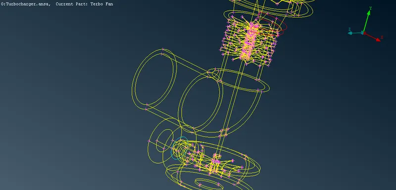
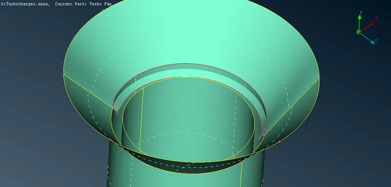
n 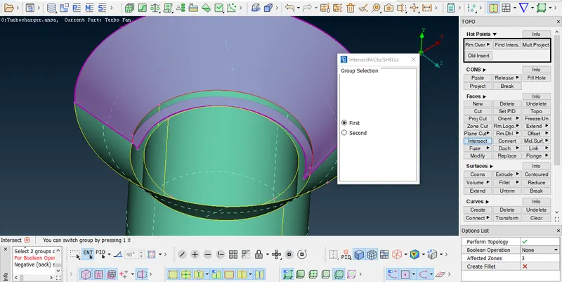
- After that need to clear the extra surfaces and overlappig surfaces on the blades, shaft rotor and impeller as shown in figs.
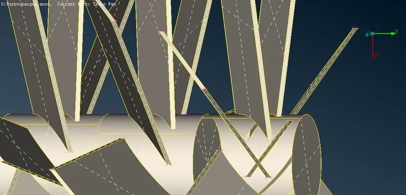
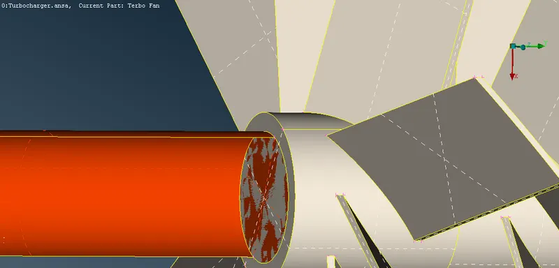
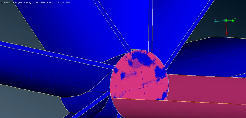
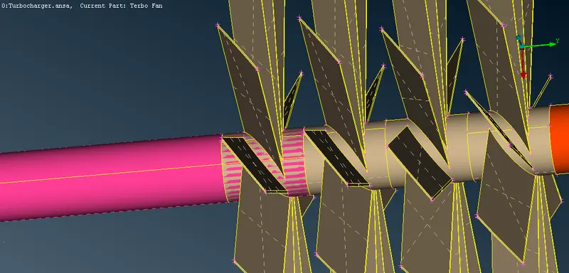
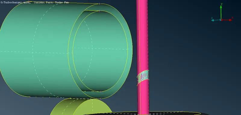
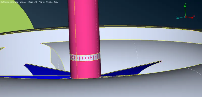
- After that need to close the open surfaces to perform CFD mesh as shown in figs.
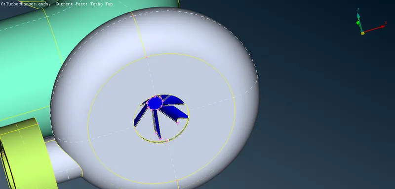
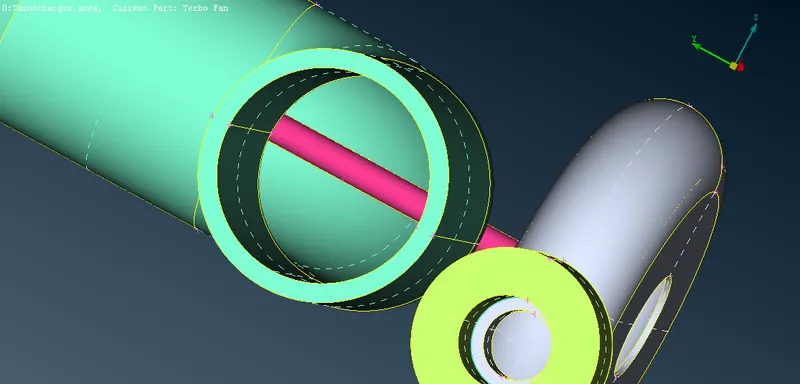
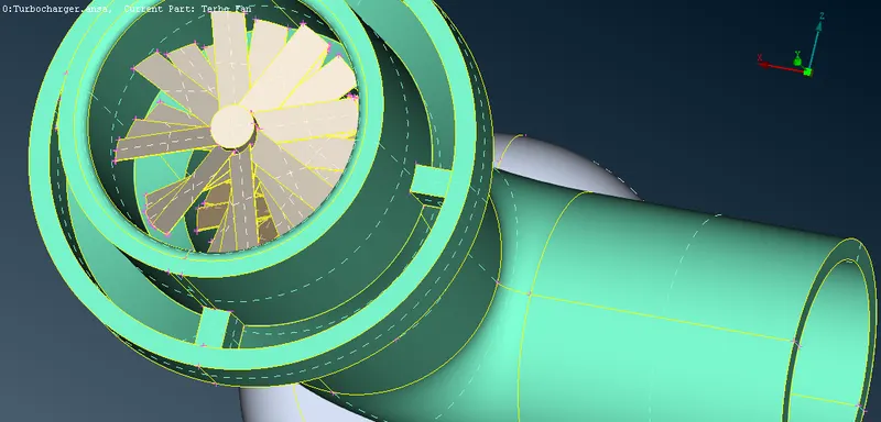
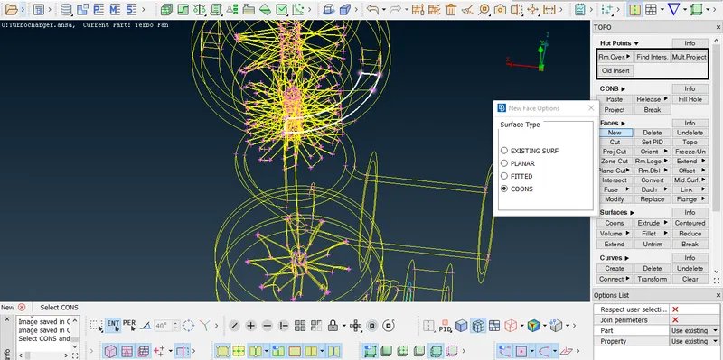
- After that need to assign the PIDs as per requirements by renaming and creating new PIDs as shown in fig.
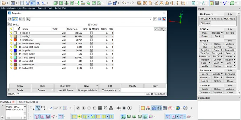
- After assigning PIDs need to perform the surface mesh operation by assigning the mesh length as per last challenge for the required mesh length for each PIDs.
- In that, some unmeshed surfaces are found due to the different mesh length to the nearby surfaces.
- To overcome that have to remesh the unmeshed surfaces by assigning the mesh length in the range condition of the nearby surfaces by repeating the same procedure
- After that full surface mesh operation completed as shown in fig.
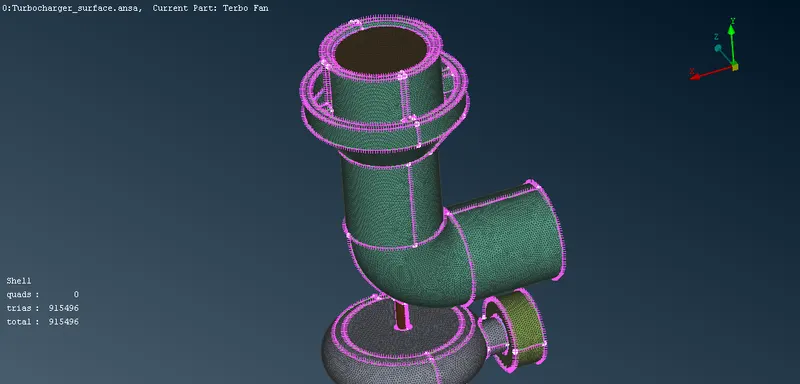
- After that need to shift the volumetric mesh mode to perform volumetric meshing operation.
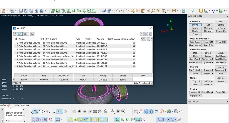
- In that first need to the define the volumes by using VOLUME>>DEFINE option as shown in fig.
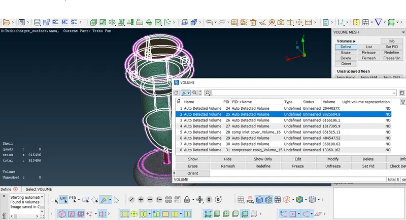
- After that need to delete the thickeness volumes of the defined list to get only the fluid flow region to perform the CFD mesh as shown in figs.
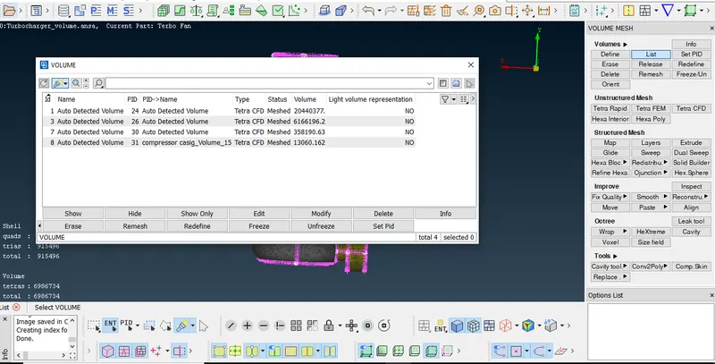
- After that need to define the mesh type as TETRA CFD in the dialogue box in volume list.
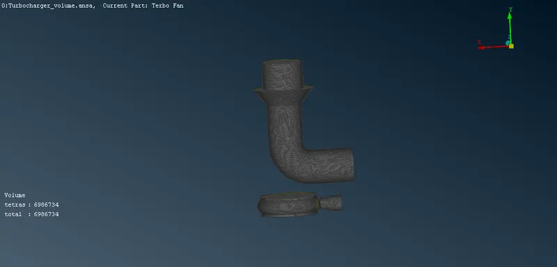
- Then need to perform the volume meshing operation by using remesh option for each volumes as shown in fig.
Result:-
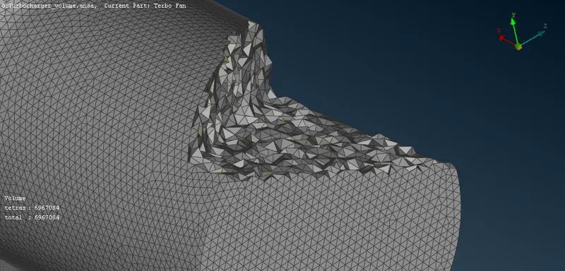
The surface mesh and volume mesh operations are done as per the requirement as shown in fig.
The link for the ANSA file of the finished operation is https://drive.google.com/file/d/1-0T0hYGdH5KSkt09c_0xNM95k_IE16mk/view?usp=sharing