Week 2 Challenge : Surface meshing on a Pressure valve
Week 2 Challenge : Surface meshing on a Pressure valve
Aim:-
To check for the geometrical errors and perform Topology cleanup accordingly, to set three different target lengths as three different cases and to perform meshing for the given model.
- Target length = 1mm, 3 mm and 5 mm (i.e. 3 cases)
- Element type = Tria
Software Used:-
ANSA v22.1.0
Procedure:-
Detecting and Clearing the Geomtrical errors:_
- First of all, Need to open the ansa file and then need to enable shadow mode to view the 3d view.
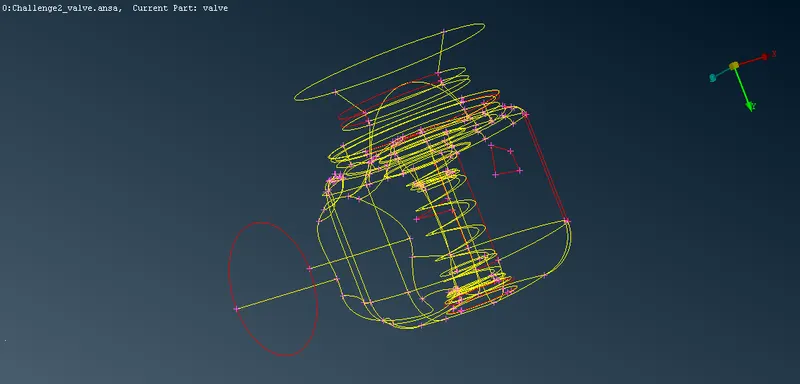
- After that we need to detect the geometrical errors such as single CONS which are in red colour by using geomtric checks options on the top window as shown in fig.
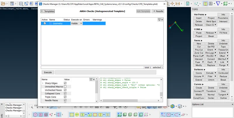
- In that dialogue box, need to execute the operation by execute option and we get the geometrical errors as shown in fig.
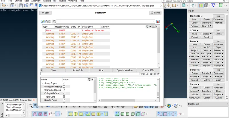
- To perform the CFD analysis we need to clear the all geometrical errors by closing the holes.
- To close the holes,there are some options in which fillhole is one of the option to fill the holes as shown in fig
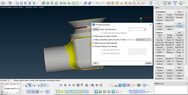
- By this method most of the single CONS are converted into double CONS.
- Eventhough fillhole option is easy to perform there are some errors we obtained while using it.
- To overcome that type of errors, need to use the FACES>>NEW and then a dialogue box will open as shown in fig
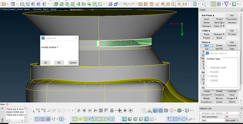
- In that we can find options as Existing surface, fitted, plane, coons. These all are the options to create the new face as per our requirement.
- In this challenge, fitted and coons options are used to do the geometrical clean up.
- After all the single cons errors are correctes need to ensure the geometric check once again as shown in fig.
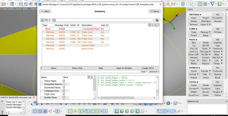
- In that, there are some more errors such as convex CONS to be corrected as shown in figg.
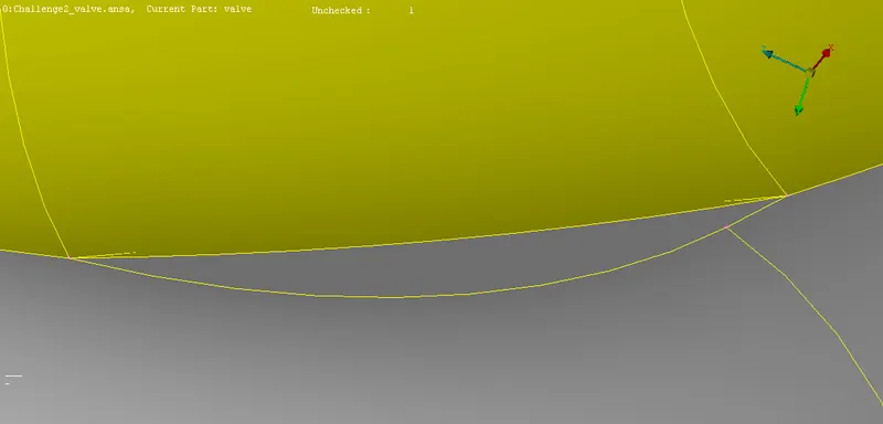
- To rectify that, need to delete the existing error creating surface by using FACES>>DELETE option and to create new surface by using fillhole option as shown in fig.
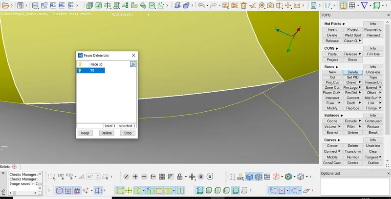
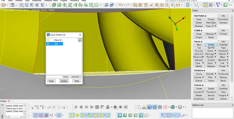
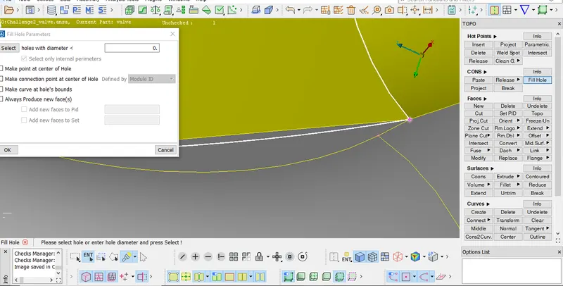
- After that need to perform geometirc check once again. In that found another error which is TOPOLOGY error as ahown in fig.
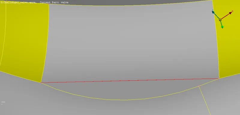
- To clear the Topology error, need to use topo option as shown in fig.
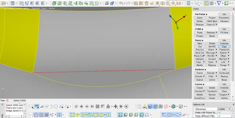
- After topo method that needle CONS go cleared.
- To ensure that need to perform geomtric check once again as shown in fig.
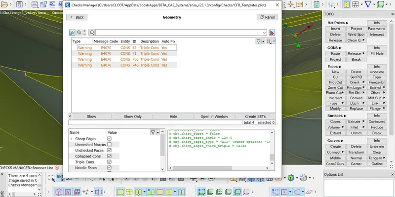
- There are only triple CONS available. Since we performing the surface meshing that triple CONS can be neglected.
Assigning PIDs:-
- To assign PIDs (property id) need to use the PID option on the top window as shown in fig.
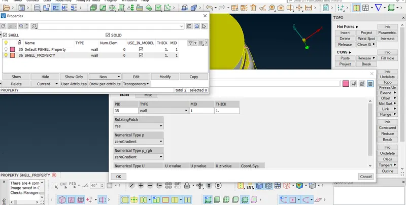
- First, need to create PIDs name after that need to assign the PID region on their respectives as per our wish by using RIGHT CLICK on the name which is need to be assigned and APPLY option.
- In this, 7 PIDs are assigned as shown in fig.
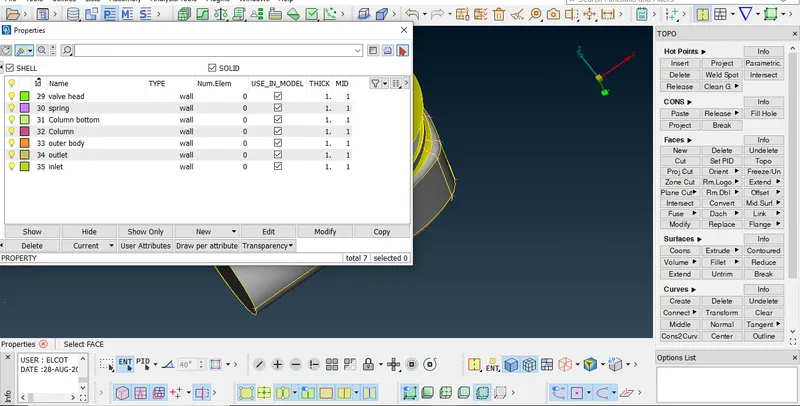
- In that dialogue box, there are some more options such as show, show only etc to make the process more effective.
Meshing:- (5mm)
- Before performing mesh need to join the small faces by using the JOIN option on the MESH mode as shown in fig.
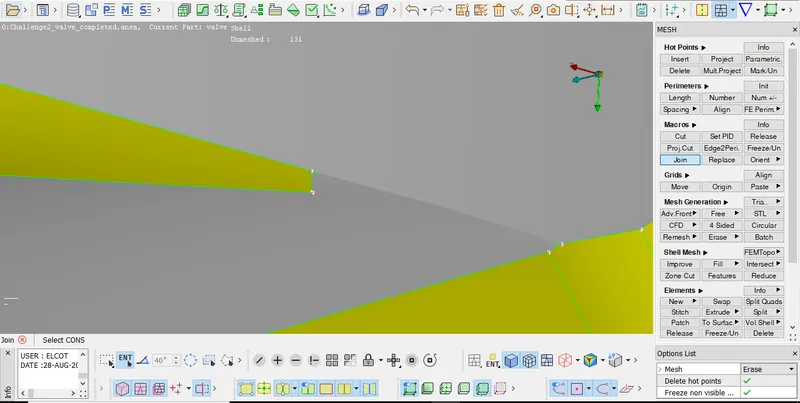
- After that, need to set the target length by using the PERIMETER>>LENGTH option. In that need to assign the perimeter's (COONS) mesh length by selecting the perimeter option. after the selecting the while perimeters by using box selection method, need to press the middle click button then need to assign the target length as 5.
- Next the same procedure should be followed in MCROS option as same as the first challenge.
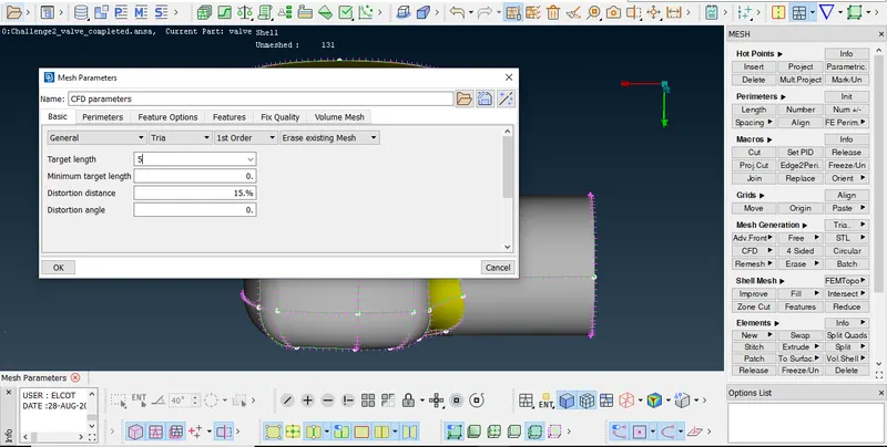
- After that, need to change mesh parameters, element type is tria by default as shown in fig for 5mm.
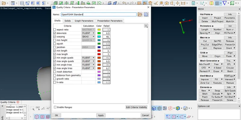
- Then need assign the Min and Max target length in the Quality criteria option as shown in fig.
- After that need to perform the meshing operation by using MESH GENERATIONS>>SPOT MESH>>VISIBLE.
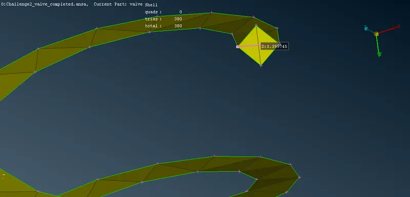
- In that, some improperly meshed surfaces are found as shown in figs.
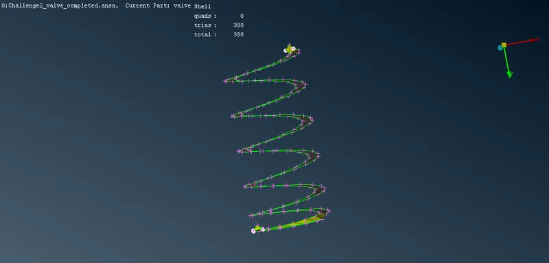
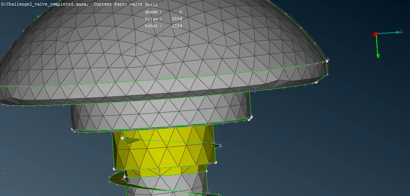
- This problem are due to meshing the length more than their suface length like spring diameter and valve head curved surface. The spring diameter is shown in fig.
- Due to that, the mesh length is needed to be reduced to1mm as well as the min and max lengths for those two PIDs by repeating the same procedure on the two PIDs only to get the appropriate meshing as shown in figs.
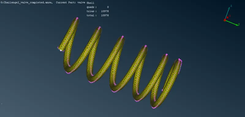
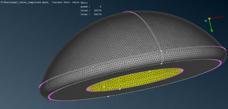
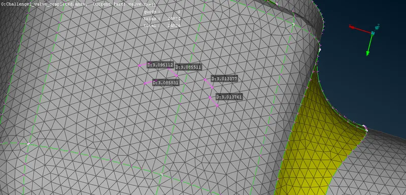
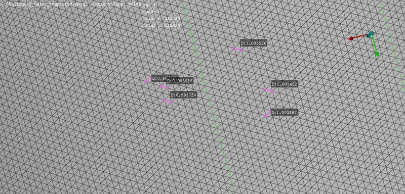
- By this method, surface meshing of the given pressure valve of 5mm mesh length was performed. To ensure the mesh length need to use the measure option.
The same method can be used to do operation for 3mm and 1mm mesh length. That images are as shown in figs.
Result:-
Suface meshing operation was done as per requirement for different mesh length and tria as the element type.
Links to view the result files,
(i) Surface meshing for 5mm mesh length - https://drive.google.com/file/d/1NPk3At03lO3CmOu8XlNfo6mDxO0LEKEx/view?usp=sharing
(ii) Surface meshing for 3mm mesh length - https://drive.google.com/file/d/1JKezVw2kjMr9r3vtlSfbpGLjIw90FjBw/view?usp=sharing
(iii) Surface meshing for 1mm mesh length - https://drive.google.com/file/d/14FNU59_whfmFeViv9_AfFgoPX4X0bMZP/view?usp=sharing
Conclusion:-
From the three different meshings 1mm mesh length is more opt to get the appropriate meshing on the Spring, valvehead as well as the overall body.
So 1mm mesh length is right option to get appropriate results.