Week 3 Challenge : CFD meshing on Turbocharger
AIM:
Check the geometrical errors to make appropriate volume,create and assign PIDs and perform surface mesh with given target lengths as per PIDs.
PROCEURE:
STEP 1:
Upload the file in ANSA software
STEP 2:
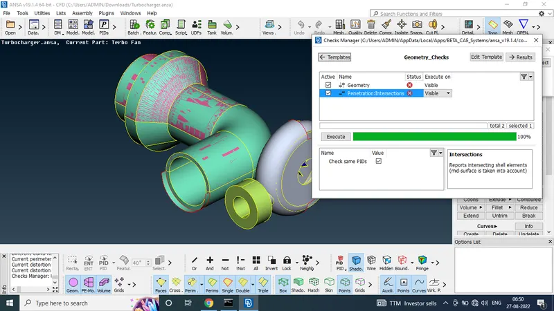
Using the check manager tool to check the GEOMETRIC CHECKS
STEP 3:
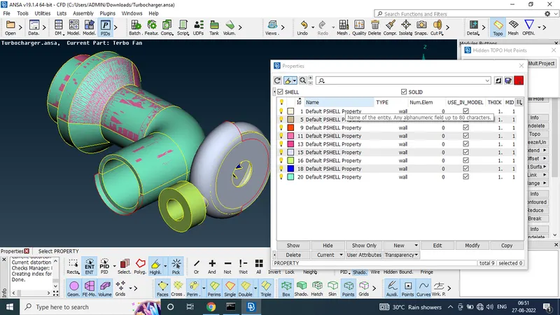
To check the PIDs
To given the model alresdy assign the PIDs names
STEP 4:
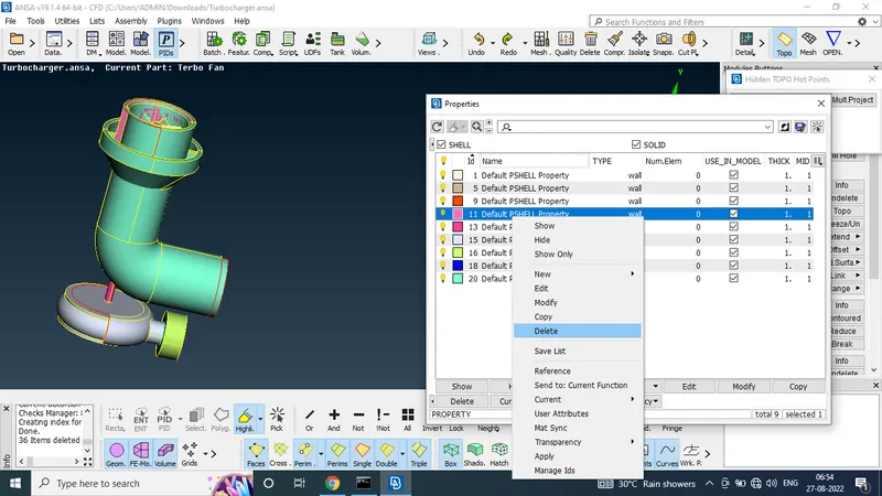
Using the PIDs Easy to delete the Extra surfaces
In the given model numer 11 is merged to extra surface so i use the PIDs and delete the surface easily.
STEP 5:
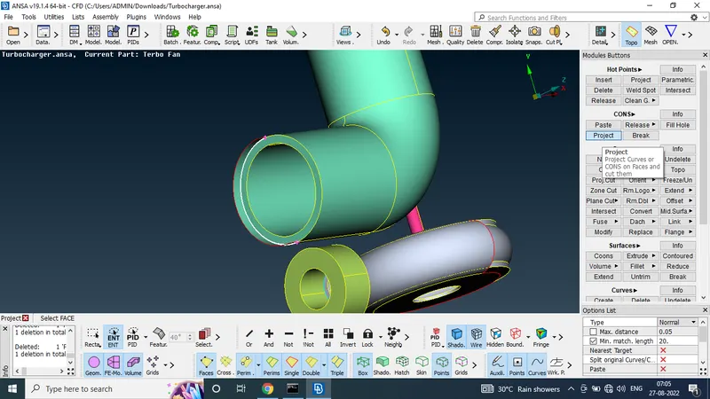
To delete the single and trible cones for the selected surface
STEP 6:
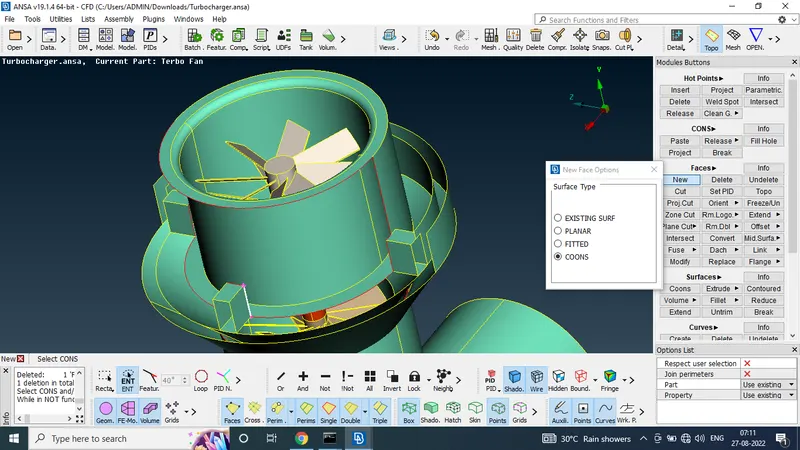
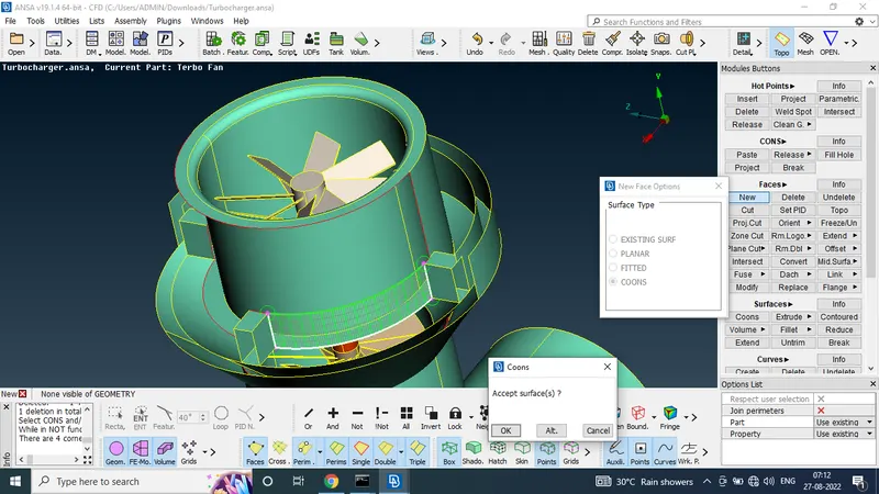
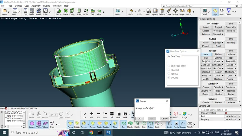
In the given model the slected area surface is not there so we use the faces and new cones tool to connecting the surfaces
STEP 7:
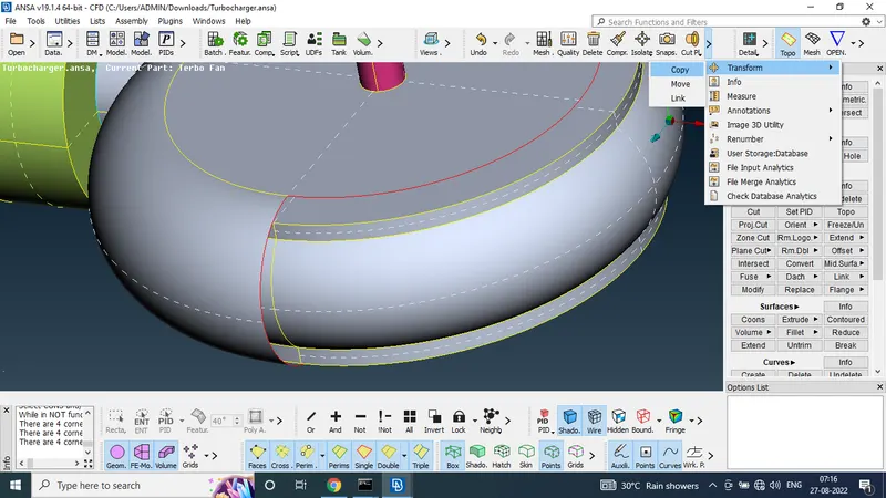
In this stage we use the transform tool to merge to faces
Before use the transform tool i need one extra hot point so i make the one new hot points to the surface.
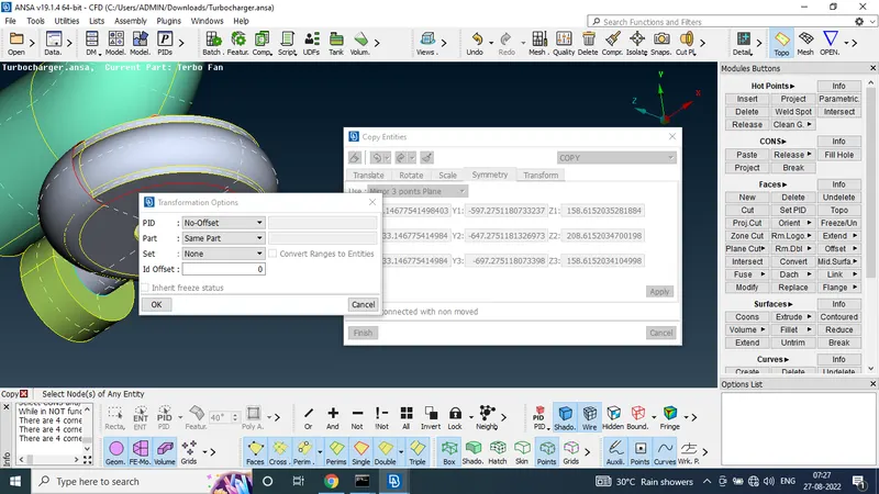
STEP 8:
Using the fill hole tool to merge the surfaces
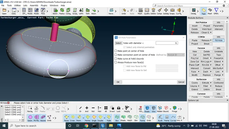
to use the topo tool to to delete the red lines
STEP 9:
in the top portion given the model was uneven so we evenly created the face
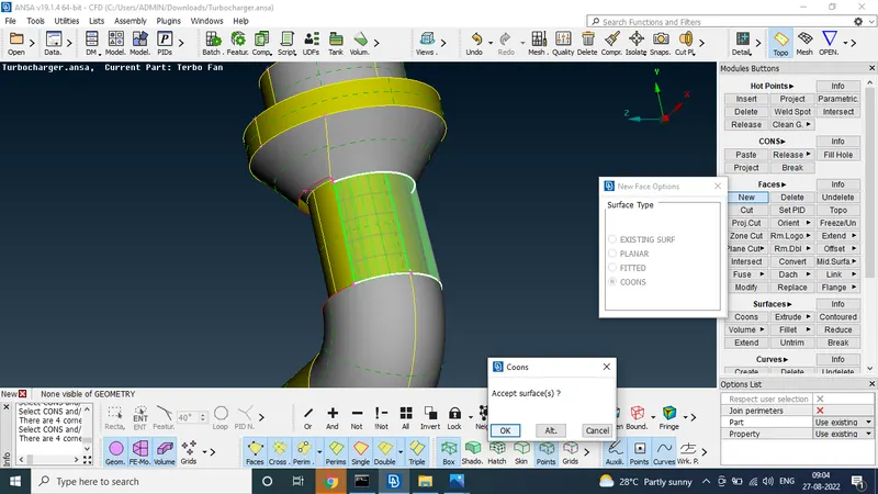
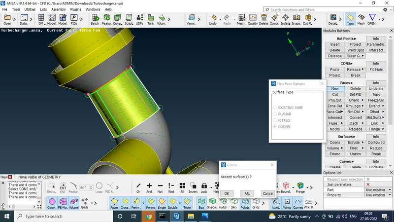
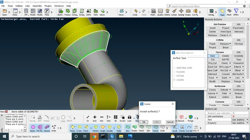
STEP 10:
connecting the all surfaces and deleting the all extra surface
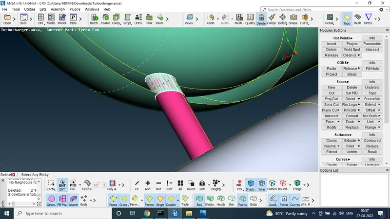
STEP 11:
deleting all penetration surface
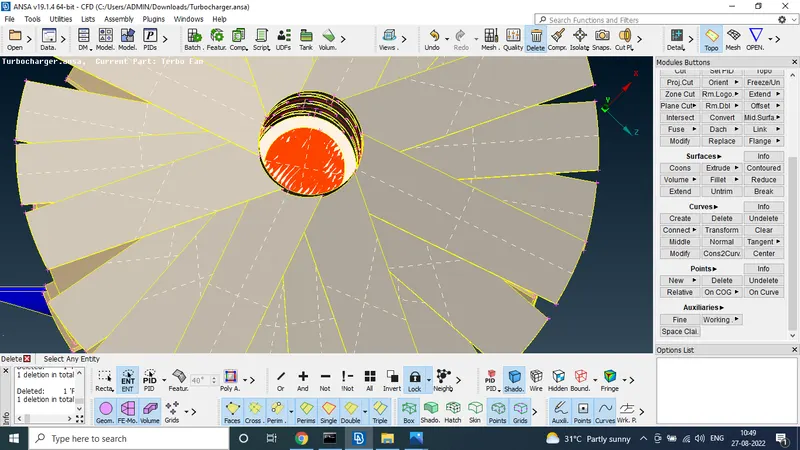
finaly we got the without giometric error surface
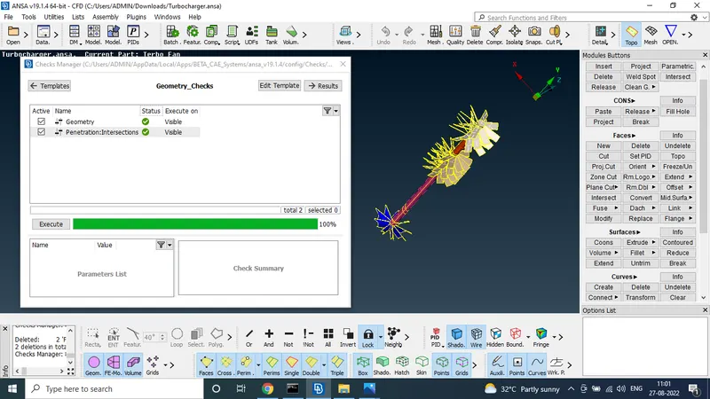
STEP 12:
going to mesh
using the surface mesh to given target lengths
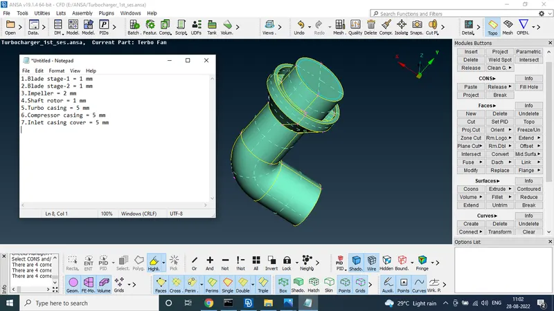
STEP 13:
tuebo casing mesh
the turbo casing surface mesh target length is 5 mm
so we use the quality and mesh criteria for min length 3 mm and max length is 7 mm
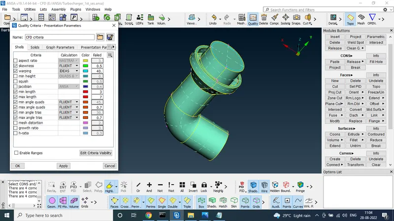
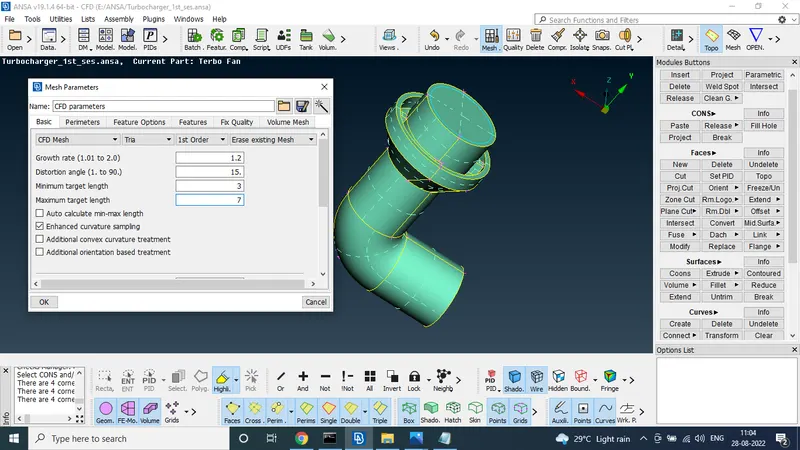
after set the mesh cretiria we use the mesh tool to mesh the turbo casing
note : paremters and macroc length is 5
after set the length i use the spot mesh to mesh the turbo case
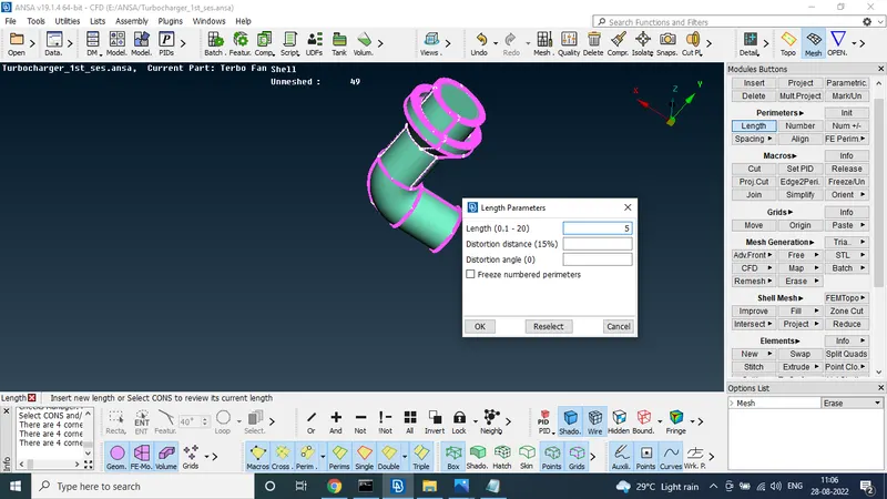
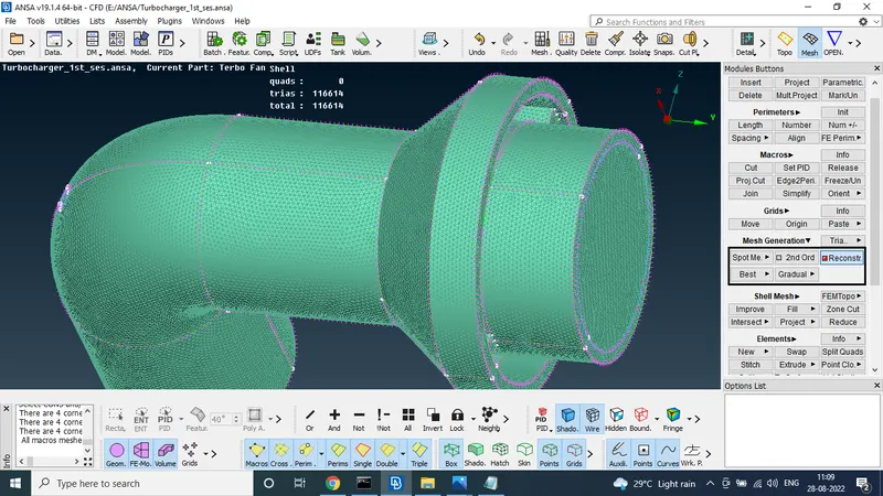
and using the or tool weather it is mesh in inside or not
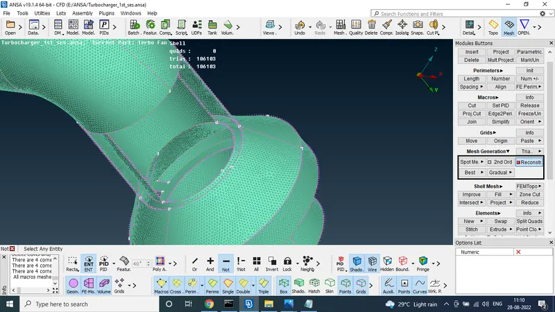
STEP 14:
at the same step 13 procetute followed by compressor surface also because our target length is 5 mm
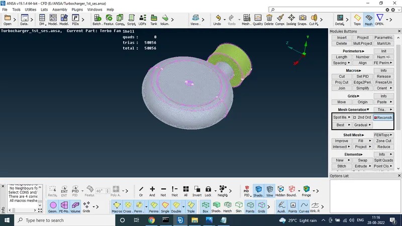
STEP 15:
usin the PIDs to select the impeler to mesh the target length 2 for above mesh procetute but targer length only different and also change in quality and mesh cretiria min and max length is 1 and 3
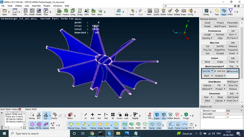
STEP 16:
in this stage shaft and blade was meshd by given length
target length is 1 mm
quality and mesh cretiria min and max length is 0.5 and 3 mm
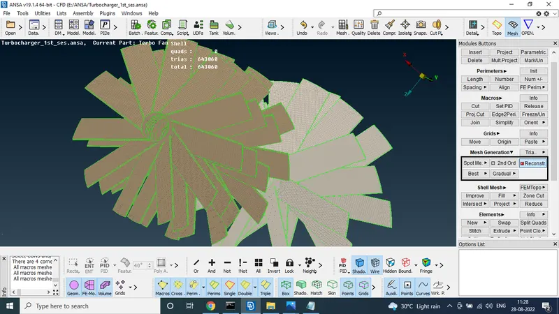
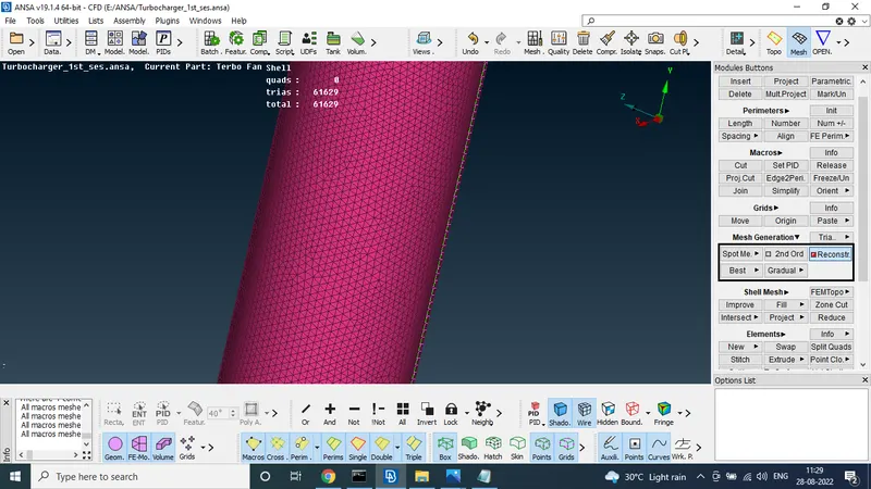
two different mesh length are connected in same area
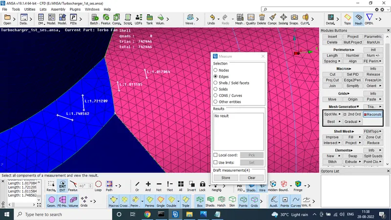
Finaly use the all comment to see the any unmesh surface
two surface was founden in unmeshed due to different mesh length
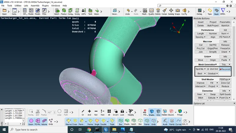
in this case to use the spot mesh directly in two surface
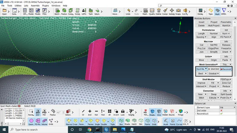
after isolated the surface to surface to use the cut option in mensioned area
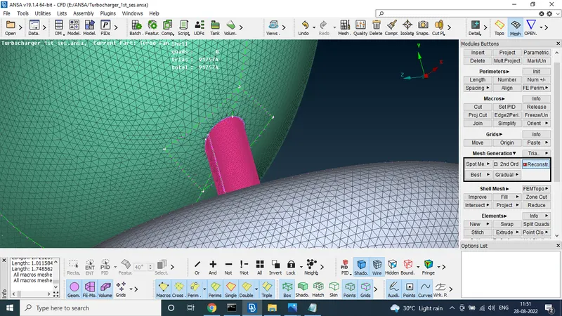
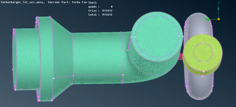
STEP 17:
finaly we get the surface mesh
STEP 18:
next stage volumetric mesh
select the volume mesh and select the volume define option in auto mode
to find the all volume
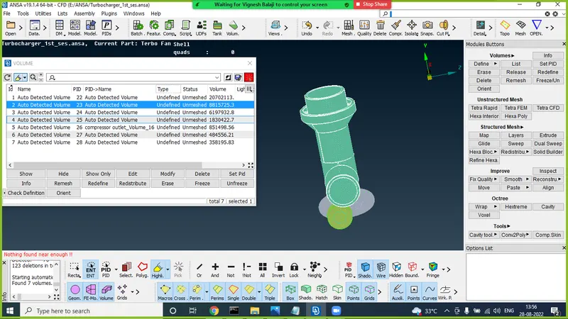
here after check the volume and delete the other surface volumes
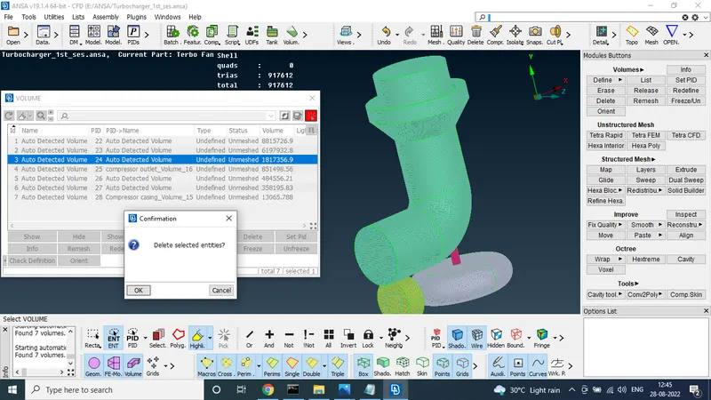
finaly we get the three volumes only
that three volumes should be mentinedd in tetra CFD
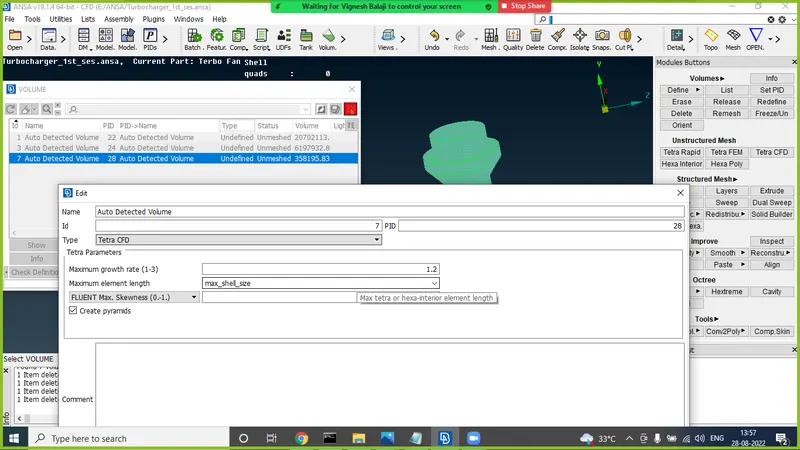
and select the three volume to use the remesh
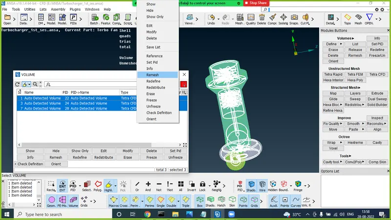
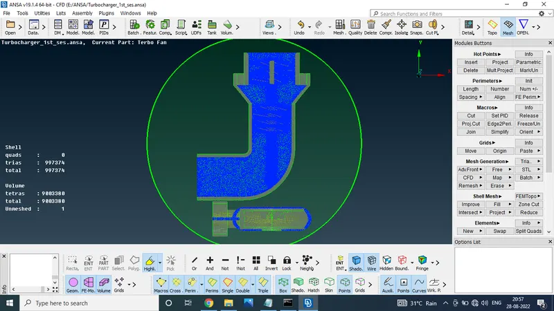
after the some time process we get the volumetric mesh tetras values 9320590
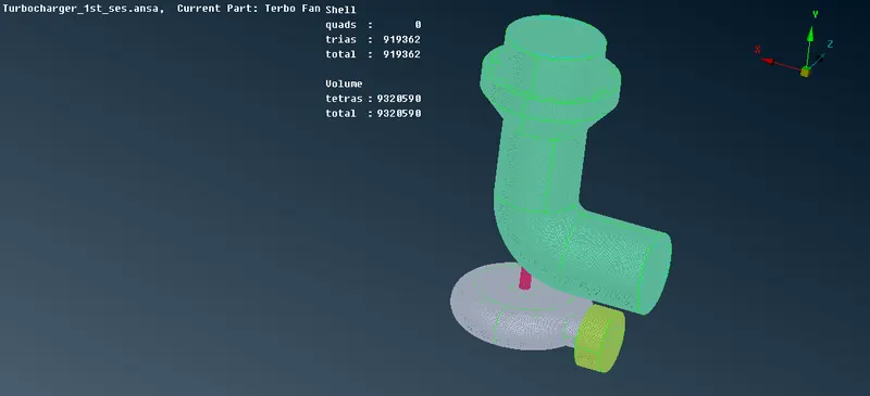
CUT SECTION VIEW
CONCLUSION:
FINALY WE GET THE SURFACE AND VOLUMETRIC MESH FOR GIVEN MODEL