Week 3 Challenge : CFD meshing on Turbocharger
Aim :
To check for errors, perform geometry cleanup, and generate a surface mesh and volumetric mesh on the turbocharger.
Introduction :
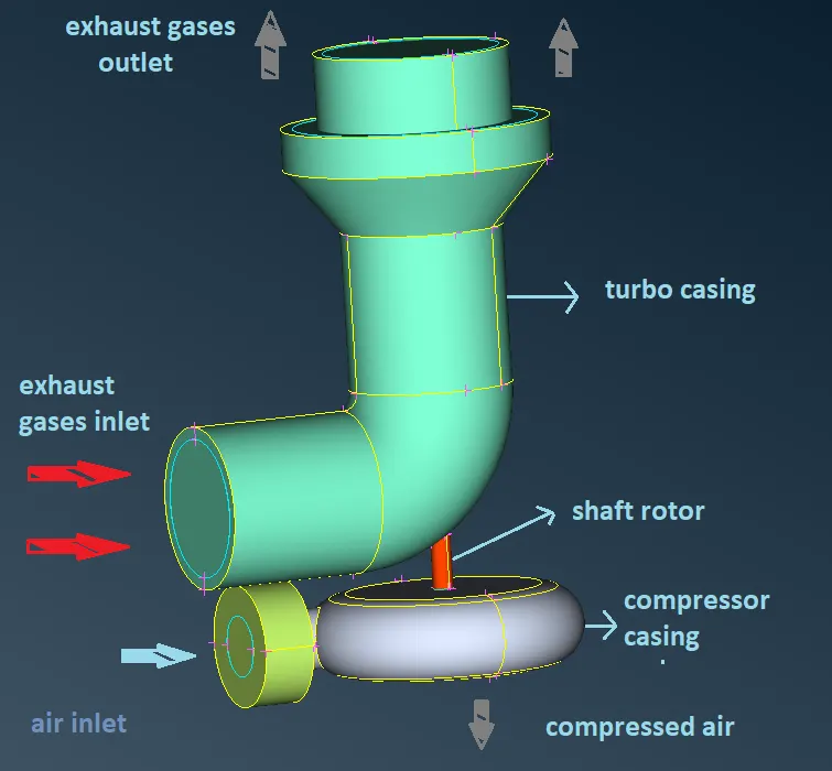
A turbocharger consists of a compressor wheel and exhaust gas turbine wheel coupled with a solid shaft that is used to boost the intake air pressure of an internal combustion engine. The exhaust gas turbine extracts energy from the exhaust gas and uses it to drive the compressor and overcome friction.
Working Methodology :
The working methodology that is followed to generate mesh on any geometry is :
1. Import the geometry.
2. Check for geometrical errors.
3. Geometry cleanup.
4. Assigning relevant PIDs.
5. Meshing.
step-1: Import the geometry
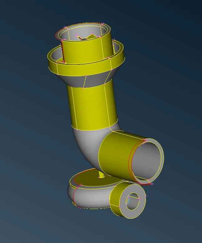
First, the pre-designed geometry of the turbocharger is imported into the ANSA.
step-2: Check for geometrical errors
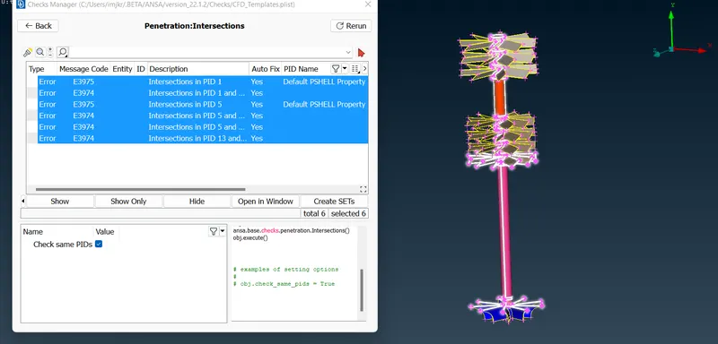
The Checks tool is used to check for geometrical errors like cracks, single CONS, intersections, penetrations, etc
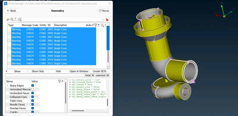
geometrical errors
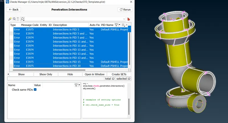
penetration & intersection errors
Step-3: Geometry cleanup
First, the geometrical errors like single CONS, and cracks are fixed by patching the faces, deleting extra surfaces, etc using project CONS, new face, topo, delete face, etc tools. Then, when fixing the intersection and penetration errors, single CONS form and have to be fixed.
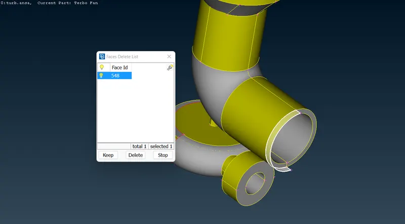
1. The Single CON is first projected on the face which creates two faces, then, the extra face is deleted.
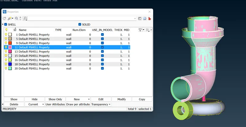
2. The overlapping PID is deleted.
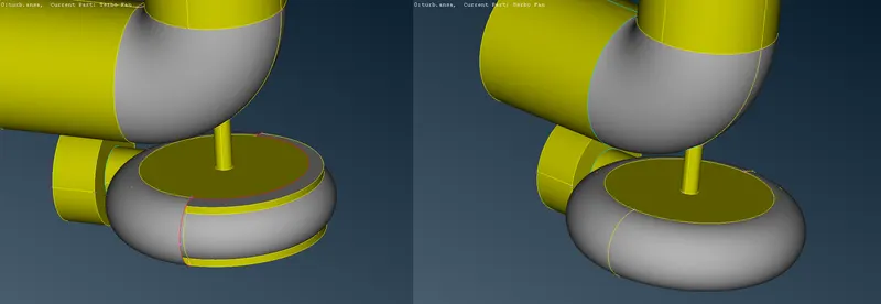
3. The missing entity is mirrored using the transform tool.
4. Two faces intersecting creating single CONS is fixed by deleting the faces and creating new faces.
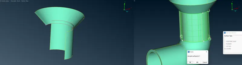
5. New face is created using the COONS method.
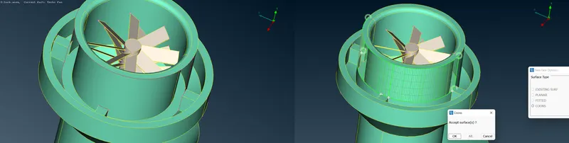
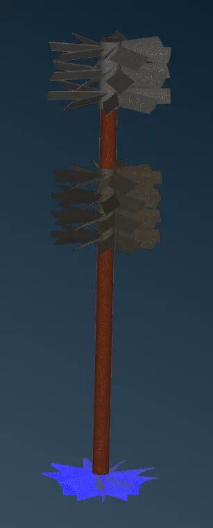
6. Multiple faces are detected in the shaft rotor, which forms an obstruction and creates different fluid volumes. So, the faces inside the shaft are deleted that leads to formation of single CONS, which is dealt using the topo tool.
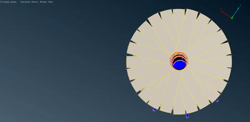
Top view showing the impellor's face
7. Overlapping region on the shaft is deleted by projecting the single CONS on the face which creates separate faces and the overlapping face is deleted.
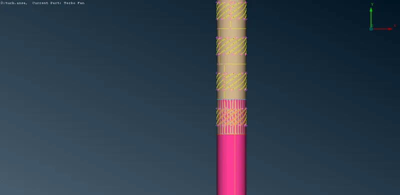
8. Similarly, the other overlapping region is also deleted which leads to the formation of single CONS, which are fixed by projecting the CONS on the face.
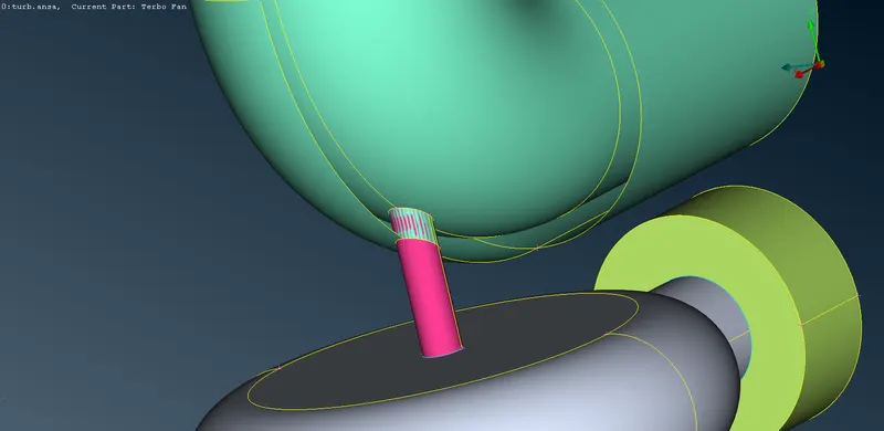
Before proceeding any further, the openings have to be closed for the detection of the fluid volume
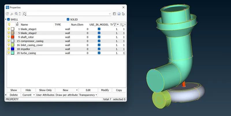
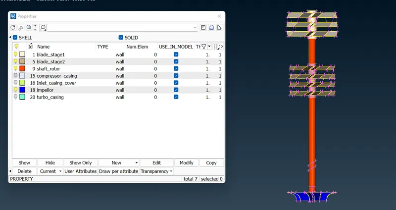
step-4 Assigning relevant PIDs
step-5 Meshing :
part-1 surface meshing
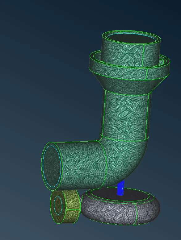
After assigning different PIDs to different parts, we can proceed further to generate the mesh. The mesh parameters like minimum and maximum target length, etc are specified.
The mesh element lengths for different components are given below:
- Blade stage-1 = 1 mm
- Blade stage-2 = 1 mm
- Impeller = 2 mm
- Shaft rotor = 1 mm
- Turbo casing = 5 mm
- Compressor casing = 5 mm
- Inlet casing cover = 5 mm
part-2 volumetric meshing
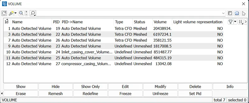
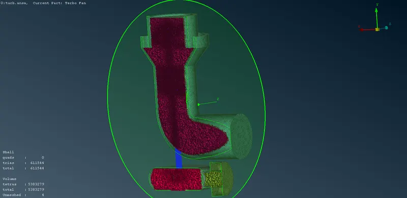
After generating the surface mesh, the define volume tool is used to detect the volumes. Both fluid volumes and solid volumes will be detected, but the focus is to generate the volumetric mesh of the fluid domain. So, the other solid volumes are deleted.
Conclusion :
Volumetric mesh with 5383279 elements is generated inside the fluid domain of the turbocharger geometry.