Week 3 Challenge : CFD meshing on Turbocharger
Aim: To rectify the topological errors in the given turbocharger model, assign appropriate PID names and perform surface and volumetric mesh with given parameters.
Objective:
- To check for the geometrical errors and perform topological clean-up.
- Assign PID names to various parts of the pressure valve.
- Specify mesh parameters and generate the surface and volumetric mesh as per the problem statement.
Terminology: The following options are used to complete our objective.
- PID – This function facilitates property management. A list of the properties existing in the file is available.
- Coons – This function facilitates property management. A list of the properties existing in the file is available.
- Fitted – The FITTED option is used for the definition of a non-planar Face. The created Face fits to the selected boundaries.
- Transform – This function is used to Translate, Rotate, Transform, Scale, Symmetry or Mirror selected entities.
- Freeze – This function locks / unlocks the selected Faces and their boundary CONS segments.
- Cut planes – Creates cutting planes by defining one point. The plane is parallel to the selected global 2D axis and passes through that point (in this exercise we used XY axis).
- Tetra CFD elements – The Tetra CFD algorithm is most suited for geometries of thick volumes, large domains with significant variation in length of the surface mesh. Most met in CFD applications.
- CFD mesh – This algorithm is an advanced meshing algorithm, that meshes with variable element length, depending on the local curvature of the underlying CAD surface.
Procedure:
The process can be done in three steps as mentioned in the objective.
Step 1:
We import the file into the ANSA software from the PC.
File -> Open -> Browse and select the file.
The model is displayed in wireframe format which is changed to Shadow mode.
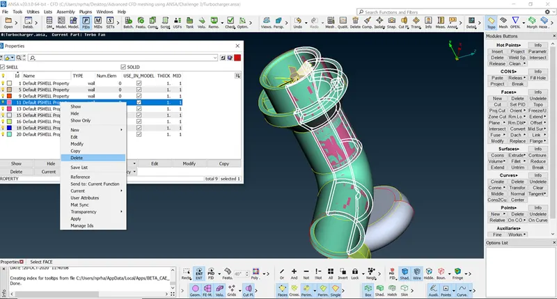
In order to perform geometry cleanup and to verify the errors we use Checks -> Geometry from the Tools ribbon on the top and execute. It shows various errors in the imported part file as shown in the following figure. The overlapping surface on the outer casing is deleted using PID command.
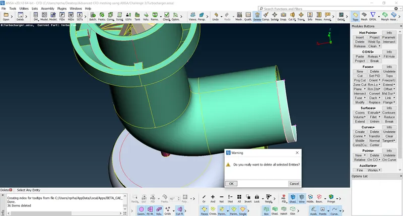
We then trim the excess surface as shown in the figure by projecting the single con onto the surface and then using universal Delete option.
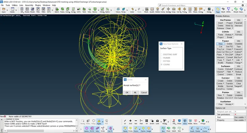
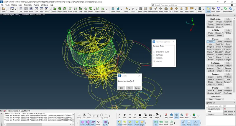
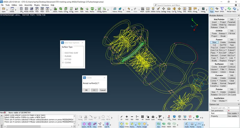
The missing surfaces are patched up by creating new surfaces using Faces -> New -> Coons -> Select the entity as shown in the following two figures.
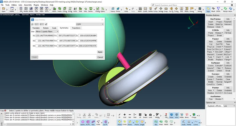
The missing surface from the turbo casing at the bottom can be created using Transform. We create a new hot point at the center of the curve as shown in the following figure. We then use Transform -> Mirror 3 points plane. A hole is generated due to the link of the selected entity with inlet casing cover. This can be rectified using Fill Hole option.
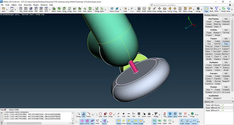
The single cons can be converted to double cons using Topo whenever necessary.
An intersection error is present at the conical surface of the turbo casing. This can be amended by deleting the unwanted surfaces and by creating new surfaces by projecting the hot points from the conical surface to the corresponding cons as shown in the following figure.
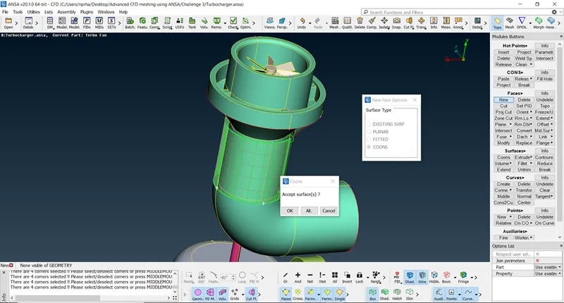
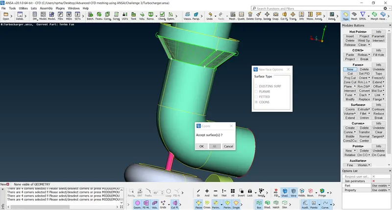
There is an opening in the turbo casing as shown in the following figure. This is sorted out by creating new surfaces.
The blue overlapping surface in the following figure is deleted using appropriate cross-hatches after projecting the cons over the pink shaft as shown in the subsequent figure.
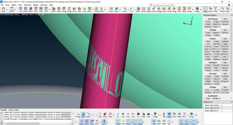
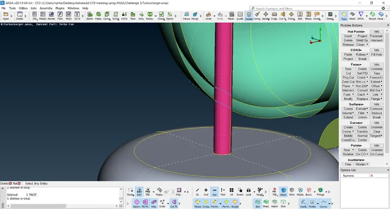
The cons on the two grey surfaces of the compressor casing as shown in previous figure are projected onto the pink shaft. The cons of the pink shaft are projected onto the blue impeller blade and the overlapping surface on the impeller is deleted. We use Topo as and when necessary.
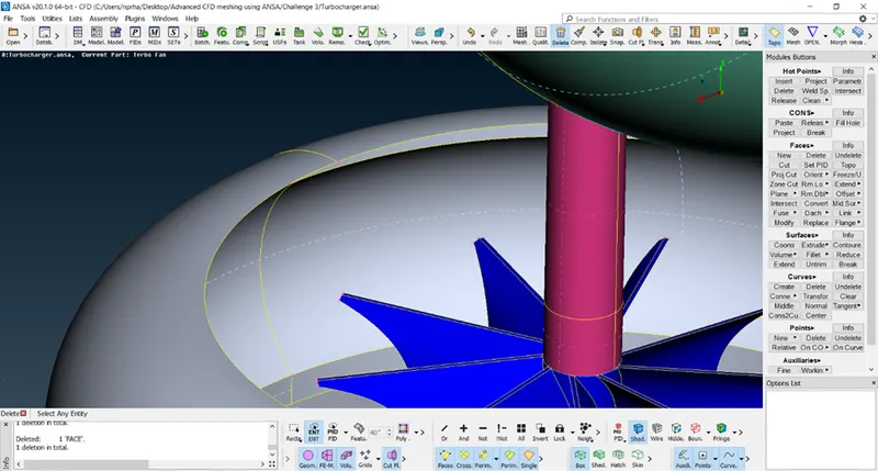
We need to delete all the unnecessary surfaces within the pink shaft throughout its length and convert the triple cons to double cons leaving only the blue surface at the bottom which is that of the impeller as shown. The top opening of the shaft is closed to ensure complete closure of the geometry.
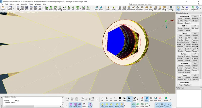
There are four openings, two at the ends of the turbo casing and one each at the end of inlet casing cover and compressor casing respectively. These are amended by creating surfaces using Faces -> New -> Fitted -> Select the entity.
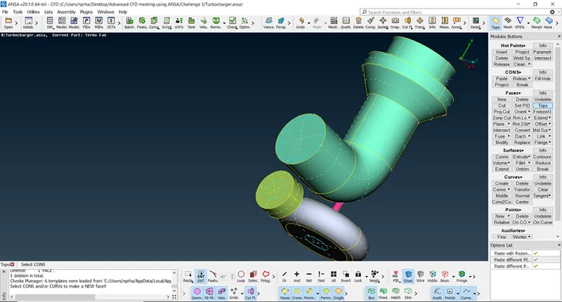
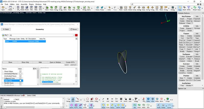
The baffle in the following figure shows an error which can be rectified by deleting one face and by recreating the face with Fill hole option. The error shown in the figure – Concave con is a warning and can be ignored just like a triple con.
Step 2:
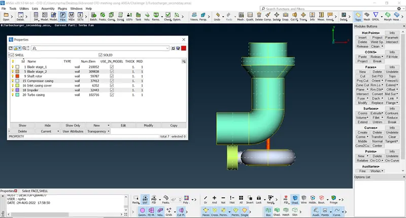
We assign PID names to various parts of the geometry for easier recognition during meshing and analysis. The PID’s can be observed using different colours.
Step 3:
Surface mesh creation:
We need to create surface mesh with triangular elements of first order for the geometry. The problem statement mentioned creating mesh with different sizes for different PID’s.
S. No | Mesh length (in mm) | PID to be meshed |
1. | 1 | Blade stage-1, Blade stage-2, Shaft rotor |
2. | 2 | Impeller |
3. | 5 | Turbo casing, compressor casing, inlet casing cover |
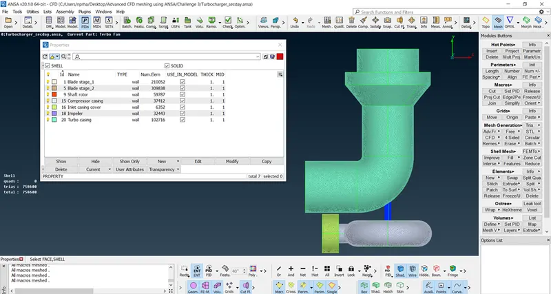
Based on the above parameters, a CFD mesh is created for the all PID’s separately as mentioned in the trailing figures.
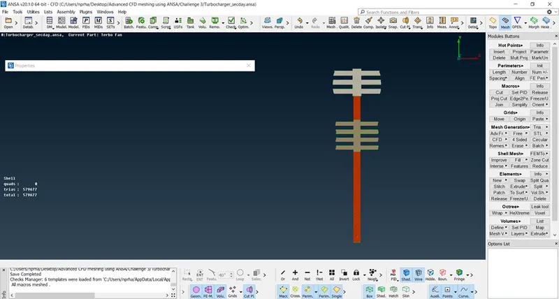
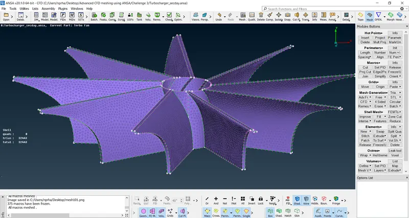
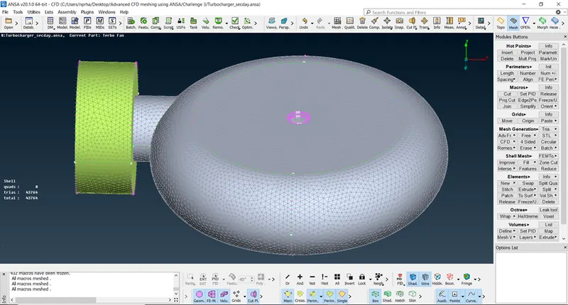
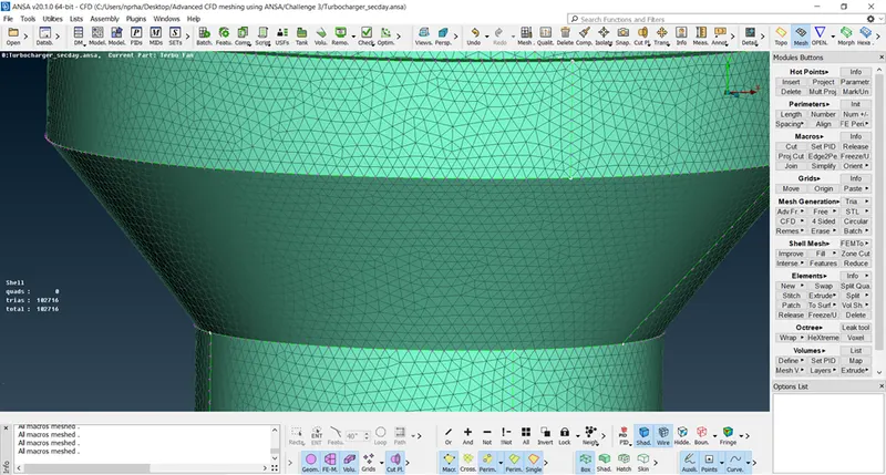
The following figure shows the number of mesh elements for various PID geometry and the total number of mesh elements in the complete geometry.
Volumetric mesh creation:
To create the volumetric mesh, it is a good practice to understand where the three- dimensional mesh is required, i.e., in this case what is the fluid domain. By not meshing the unwanted volumes, we can reduce the number of mesh elements drastically which in turn optimizes the computational time.
We can go to Volumes -> Define -> OK. This would determine different volumes present in our geometry. We use Volumes -> List, to check the volumes that are necessary and we can delete the other volumes. This will not delete the geometry but the volumetric mesh will not be applied to deleted volumes. We would select all the required volumes and click Remesh as shown in the figure.
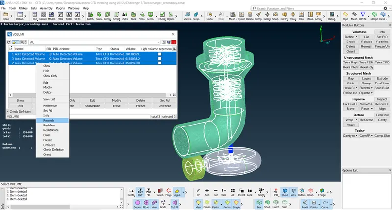
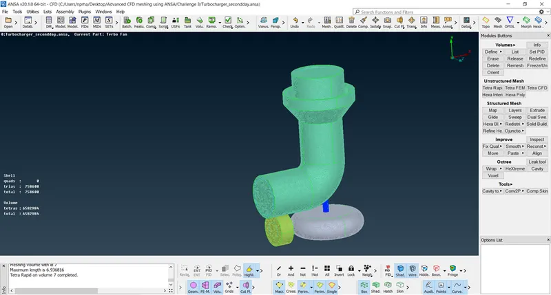
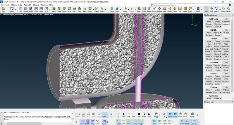
The Remesh command generates the volumetric mesh in the selected volumes as shown in the figure. We see that 65,82,984 tetra CFD elements are created. If we select all the volumes defined in the geometry, a lot more unwanted mesh elements would be created which would waste a lot of processing power and computational time.
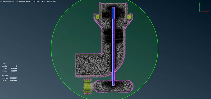
We will use Cut planes -> Default XY and click the hot point on the top surface of the turbo casing which would create a sectional view of the entire geometry showing the volumetric elements as shown in the following figure.
Conclusion:
Hence, we have created the surface mesh and volumetric mesh for the given geometry with the specified parameters.
It is observed that 7,58,600 triangular surface mesh elements and 65,82,984 tetra CFD elements are created.
The meshed geometry file is saved and can be accessed using the following google drive link.
https://drive.google.com/file/d/1RUz3HdmvPgfCOy_s9POEpryK1BogQclX/view?usp=sharing
References: