Project 1 : CFD Meshing for Tesla Cyber Truck
Aim: To generate surface mesh for the given Tesla cyber truck model and an enclosure for aerodynamic study with the specified parameters.
Objective:
- To check for the geometrical errors and perform topological clean-up.
- Assign PID names to various parts of the cyber truck.
- Specify mesh parameters and generate the mesh for the truck as per the problem statement.
- Create and perform surface mesh over an enclosure with appropriate dimensions.
Terminology: The following options are used to complete our objective.
- PID – This function facilitates property management. A list of the properties existing in the file is available.
- Coons – This function facilitates property management. A list of the properties existing in the file is available.
- Fitted – The FITTED option is used for the definition of a non-planar Face. The created Face fits to the selected boundaries.
- CFD mesh – This algorithm is an advanced meshing algorithm, that meshes with variable element length, depending on the local curvature of the underlying CAD surface.
- Orient Auto [Grey outside volume] – This function turns the outside direction of visible closed volumes to grey. The mesh elements that will be generated, or those already existing, also obtain a uniform orientation.
- Relative – This function defines new 3D-points that lie on a given relative position from a number of selected 3D-points, Hot Points, Weld Points etc. The input of a (dx, dy, dz) vector, or an indication by the mouse is required for the definition of the relative position.
- Create – This function creates smooth 3D-curves, polylines, circles and ellipses, by defining a number of points with the help of geometric and element entities.
- Split – This function splits quadrilateral and triangular shell elements into smaller ones.
- Freeze/Un – This function locks/unlocks the selected Macro Areas and their boundary segments.
Procedure:
The process can be done in four steps as mentioned in the objective.
Step 1:
We import the file into the ANSA software from the PC.
File -> Open -> Browse and select the file.
The model is displayed in wire frame mode by default. We can see the model is composed entirely of red cons. This might be due to disconnected surfaces. These errors can be resolved using Topo.
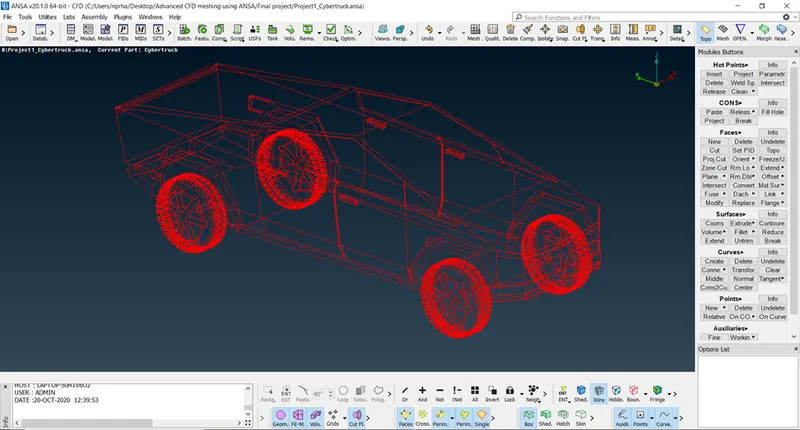
We can still see a few single cons in the following figure, these are the errors we need to resolve.
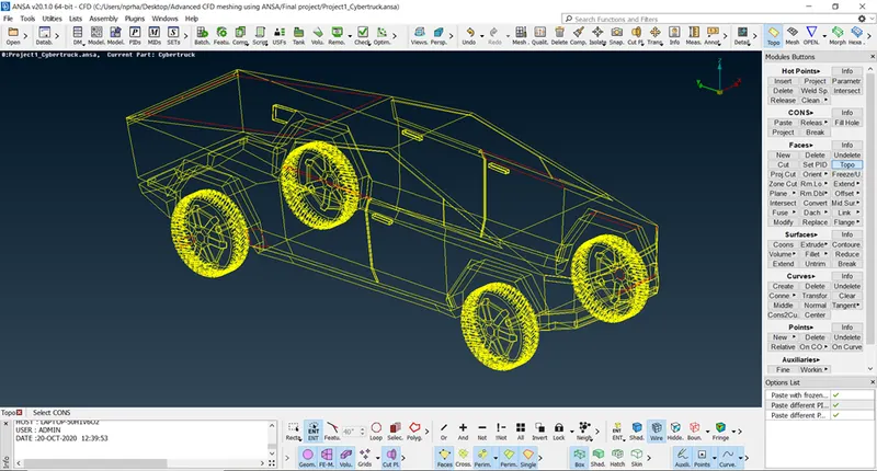
In order to perform geometry cleanup and to verify the errors we use Checks -> Geometry from the Tools ribbon on the top and execute. It shows various errors in the imported part file.
We can disable double cons to help us visualize the location and the number of single cons in the geometry as shown in the following figure.
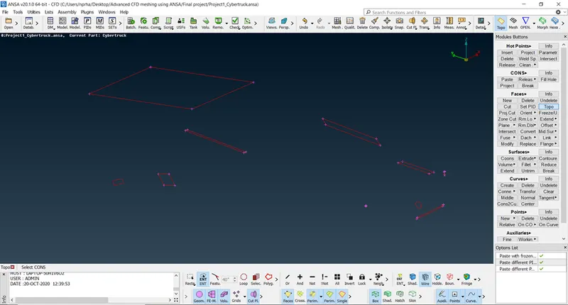
After we resolve the single cons, we would proceed to resolve the intersection errors in the geometry as shown in the following figure.
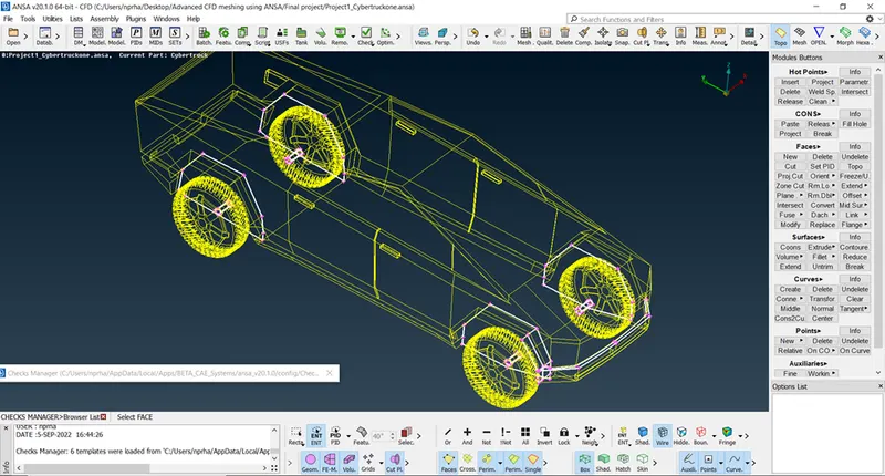
There are five instances of intersection errors, one near the bonnet and four errors around the wheel portion of the truck. These cases are resolved using appropriate methods.
We observe a number of unwanted surfaces in the geometry as shown in the following figure. These surfaces cause triple cons in the geometry. We can erase these surfaces if they don’t have any significance.
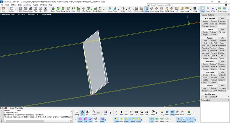
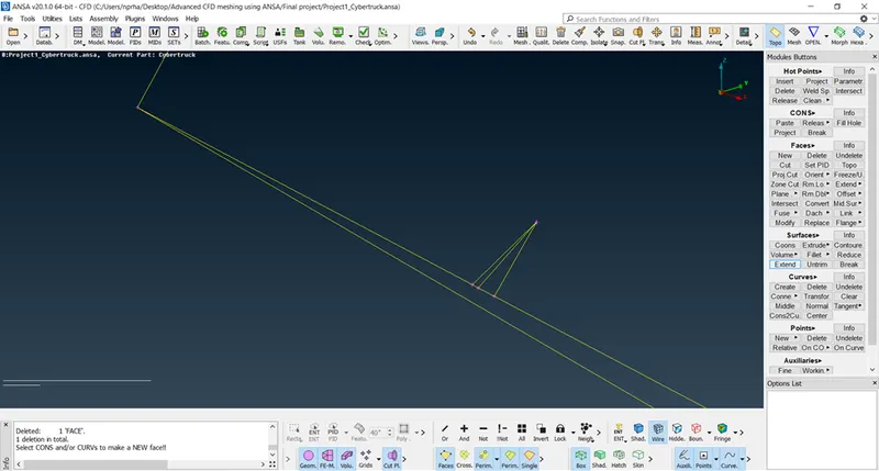
There are other types of unwanted surfaces as in the following figure. These are not reflected in the geometry check since they are composed of double cons and also not cause penetration errors. We need to eliminate these unwanted surfaces to have proper surface mesh.
Step 2:
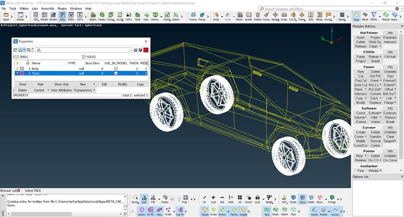
We assign PID names to various parts of the geometry as mentioned in the problem statement for easier recognition during meshing and analysis.
Step 3:
We need to create mesh with triangular elements of first order for the geometry with appropriate mesh element criteria to have minimum number of elements and also capture the flow physics during analysis.
We decided to use mesh element length as 2mm and 3mm for tyres and body respectively.
|
Mesh element length (in mm) |
Minimum length (in mm) |
Maximum length (in mm) |
PID’s assigned |
|
2 |
1 |
3 |
Tyres |
|
3 |
2 |
7 |
Body |
From the PID properties, we keep only the required visible and disable visibility of other parts by turning off the bulb present on the left side of each part.
We use Mesh -> Perimeters -> Length and specify length and click OK. We enter the same value for the Macros as well.
We navigate to Utilities window, Mesh -> Basic -> CFD Mesh and set the min. and max. target lengths and select first order Tria elements.
Later, we use Mesh generation -> CFD -> Visible, to generate a uniform first order triangular surface mesh as shown. (We need to long press the left mouse button over CFD to see the visible option).
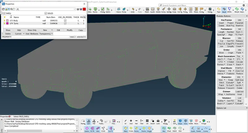
The tyres have 51,69,636 surface mesh elements as shown in the following figure.
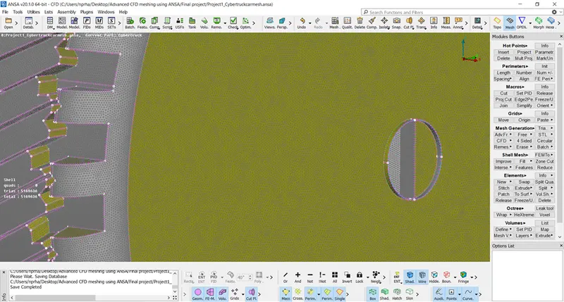
The body has 35,99,372 surface mesh elements as shown in the following figure.
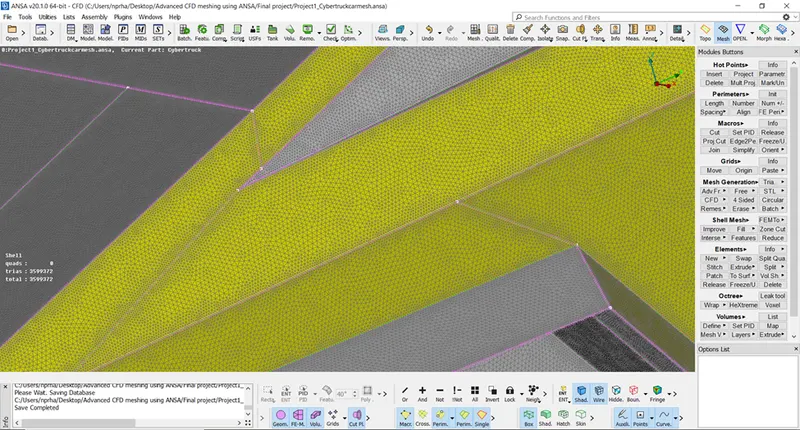
We freeze the PID’s that are meshed before proceeding with the next PID to prevent erasure of the mesh in the previously meshed PID’s. The truck after meshing has 87,69,008 elements in the entire geometry.
Step 4:
In order to study the aerodynamic performance of the given cyber truck, we need to create an enclosure over the geometry with the following parameters.
The length, width and height of the car are 5900mm, 1880mm and 1950mm respectively. (The values are obtained from the model.)
|
S.No |
Dimension (in mm) |
Designated variable |
Enclosure Dimensions required |
|
|
Requirement |
Value(in mm) |
|||
|
1. |
5900 |
x |
Front – 4x |
23600 |
|
Rear – 6x |
35400 |
|||
|
2. |
1880 |
y |
Left - y |
1880 |
|
Right - y |
1880 |
|||
|
3. |
1950 |
z |
Top – 3z |
5850 |
|
Bottom - NA |
0 |
|||
We create 3D points using Topo -> Points -> Relative. After creating required points, we create a curve between the points using Topo -> Curves -> Create. We can create the rest of the enclosure using Coons option.
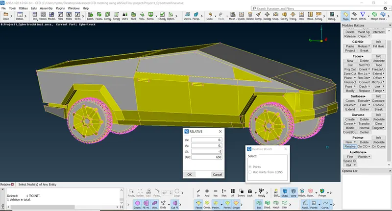
We can delete the 3D points and corresponding curves after creating the enclosure. We assign the PID names for the enclosure as shown in the following figure.
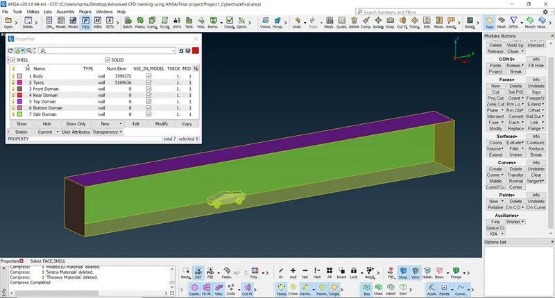
A small gap is left between bottom domain and tyres of the car to prevent any possible errors while enclosure meshing and analysis.
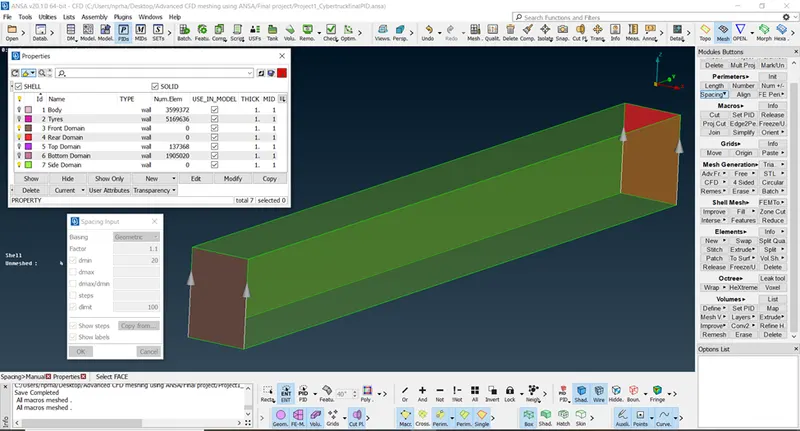
We mesh the bottom and top domain with mesh element size of 20mm and 100mm respectively. We then use Mesh -> Perimeters -> Spacing with Dstart-20mm, Dlimit-100mm and growth ratio-1.1 to create uniformly varying mesh in the sides of the enclosure as shown in the figure.
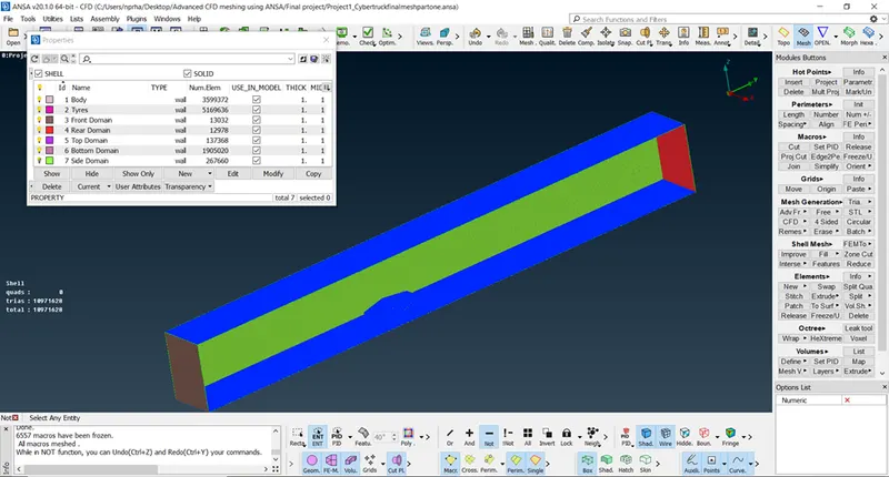
The final meshed geometry after performing surface mesh over the car and the enclosure is shown as follows.
Learning Outcomes:
- Verify the topological errors in the imported geometry file and rectifying them using various tools available in ANSA.
- To eliminate the small surfaces across the geometry to prevent off elements in the mesh.
- To generate a mesh using different algorithms and using different tools available.
- Creating 3D points and curves as necessary to create enclosures and other necessary surfaces.
- Defining and meshing volumes as per the given parameters.
Conclusion:
Hence, we have created the surface mesh for the given cyber truck model and the enclosure with the assumed parameters.
The number of mesh elements in the truck and the enclosure are 87,69,008 and 22,02,620 respectively. Hence the total number of surface mesh elements are 1,09,71,628. There are no Off-elements in the surface mesh.
The shafts connecting the wheels to the truck body are joined to the truck body while assigning PID. This would ensure four tyres and one single body volume thus making volumetric meshing easier.
Volumetric mesh in the enclosure couldn’t be performed due to limited processing power of the system used for working on the given geometry.
Errors like concave cons, convex cons and mixed cons occurred during the course of geometry clean-up, these errors can be resolved by splitting the surfaces using Face -> Cut or by deleting the existing surfaces and creating the new surfaces. For this geometry, these errors don’t create any issues and can be ignored.
The meshed geometry is saved and can be accessed using the following google drive link.
https://drive.google.com/file/d/12eJYYkBJYEFx-TQp-gFoOYPUOwSLSmj8/view?usp=sharing
References: