Week 2 Challenge : Surface meshing on a Pressure valve
Aim: To generate surface mesh for the given pressure valve with the specified parameters.
Objective:
- To check for the geometrical errors and perform topological clean-up.
- Assign PID names to various parts of the pressure valve.
- Specify mesh parameters and generate the mesh as per the problem statement.
Terminology: The following options are used to complete our objective.
- PID – This function facilitates property management. A list of the properties existing in the file is available.
- Coons – This function facilitates property management. A list of the properties existing in the file is available.
- Existing surf – This function facilitates property management. A list of the properties existing in the file is available.
- Fitted – The FITTED option is used for the definition of a non-planar Face. The created Face fits to the selected boundaries.
- CFD mesh – This algorithm is an advanced meshing algorithm, that meshes with variable element length, depending on the local curvature of the underlying CAD surface.
Procedure:
The process can be done in three steps as mentioned in the objective.
Step 1:
We import the file into the ANSA software from the PC.
File -> Open -> Browse and select the file.
The model is displayed in wireframe format which is changed to Shadow mode.
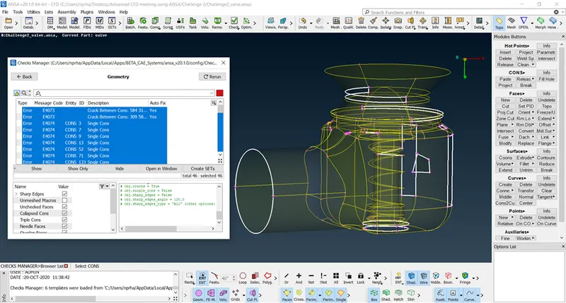
In order to perform geometry cleanup and to verify the errors we use Checks -> Geometry from the Tools ribbon on the top and execute. It shows various errors in the imported part file as shown in the following figure.
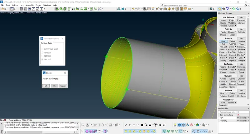
The model should be completely closed to perform meshing. We close the outlet of the pressure valve by using Faces -> New -> Coons ->Select the entity as mentioned in the figure.
We create surfaces in two other instances in the same way as mentioned in the following figures.

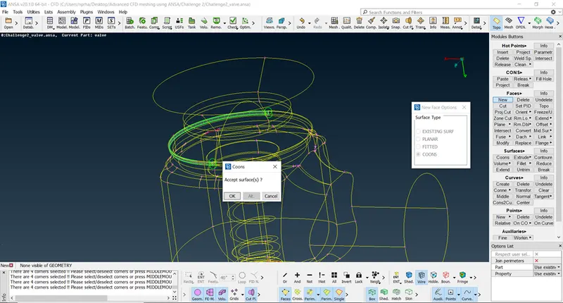
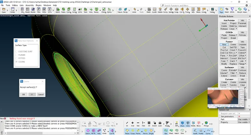
We then proceed to close the holes in the geometry using CONS -> Fill hole -> Select the hole.
There are six holes in the geometry that can be rectified using this command as shown in the following figures.
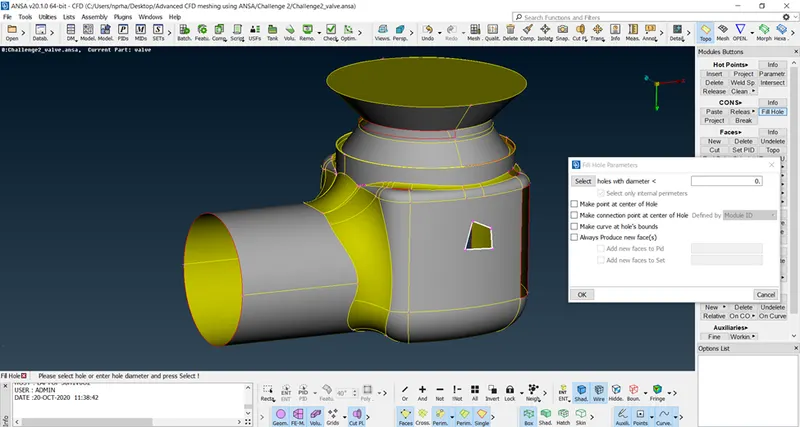
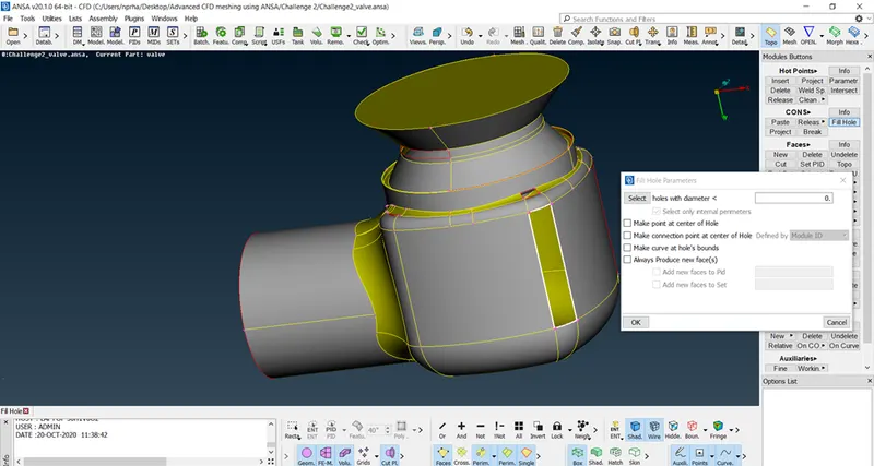
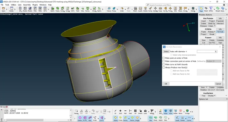
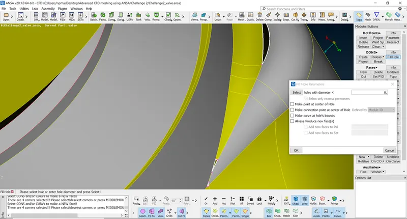
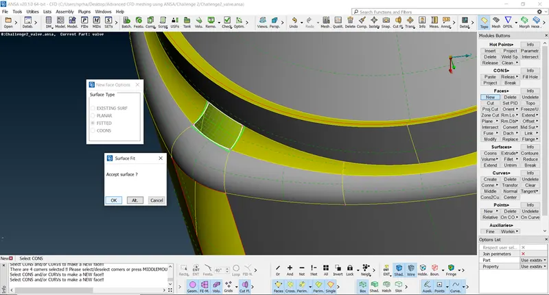
The gap at the curve of the geometry as shown in the following figure is closed by using Faces -> New -> Fitted -> Select the entity.
Step 2:
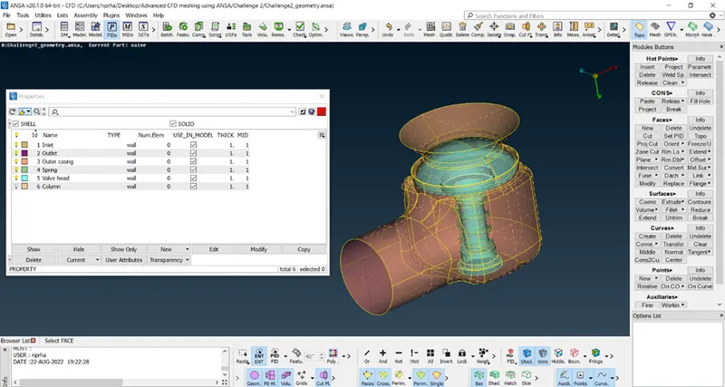
We assign PID names to various parts of the geometry for easier recognition during meshing and analysis.
Step 3:
We need to create mesh with triangular elements of first order for three cases with length 5mm, 3mm and 1mm for the as mentioned in the problem statement. It is recommended to use 1mm mesh for the spring for all cases to prevent severe deformation of the geometry.
Case 1:
From the PID properties, we keep only the spring visible and disable visibility of other parts by turning off the bulb present on the left side of each part.
We use Mesh -> Perimeters -> Length and specify length as 1mm and click OK. We enter 1mm for the Macros as well.
This would generate nodes at the distance of 1mm on all cross hatches.
We navigate to Utilities window, Mesh -> Basic -> CFD Mesh and set the min. and max. target lengths as 0.5mm and 2mm respectively and select first order Tria elements as shown.
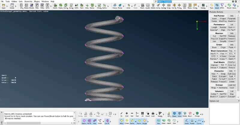
Later, we use Mesh generation -> CFD -> Visible, to generate a uniform first order triangular surface mesh with element size 1mm as shown. (We need to long press the left mouse button over CFD to see the visible option).
We use Mesh -> Perimeters -> Length and specify length as 5mm and click OK. We enter 5mm for the Macros as well.
This would generate nodes at the distance of 5mm on all cross hatches.
We navigate to Utilities window, Mesh -> Basic -> CFD Mesh and set the min. and max. target lengths as 3mm and 7mm respectively and select first order Tria elements as shown.
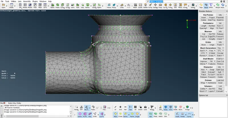
Later, we use Mesh generation -> CFD -> Visible, to generate a uniform first order triangular surface mesh with element size 5mm as shown.
We then create the mesh for the element size of 3mm by providing minimum and maximum lengths of 1mm and 5mm respectively.
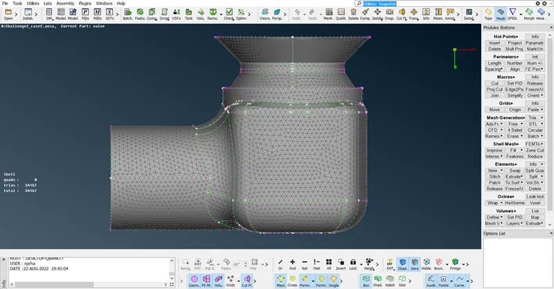
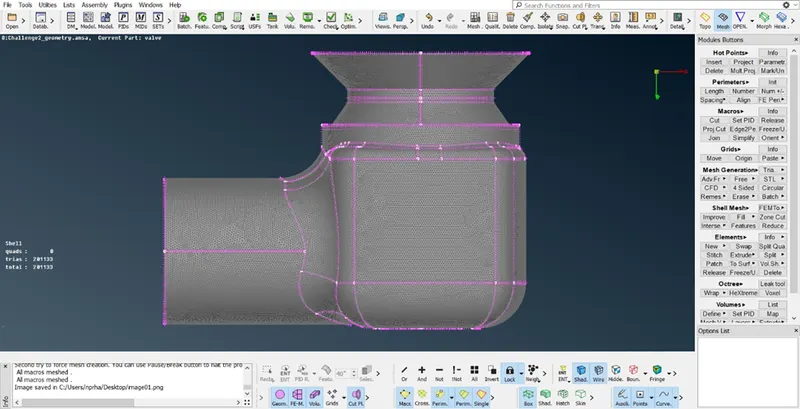
Later we create the mesh for the element size of 1mm by providing minimum and maximum lengths of 0.5mm and 2mm respectively.
Conclusion:
Hence, we have created the surface mesh for the given geometry with the specified parameters.
It is inferred during the meshing process that the geometry of the valve head was slightly deformed with 5mm mesh size, which got resolved with 3mm mesh size. So, for the best outcome we need to mesh the spring and valve head with 1mm and 3mm respectively and the rest of the geometry with 5mm element length.
As the number of elements in the geometry increases, the computational time as well as the accuracy of analysis increases. The number of elements for each case is mentioned below.
|
S. No |
Mesh element length (in mm) |
No. of meshed elements in the spring |
Total no. of meshed elements |
|
1. |
5 |
10620 |
16354 |
|
2. |
3 |
10620 |
34167 |
|
3. |
1 |
10620 |
201133 |
The meshed geometry files for the three element lengths are saved and can be accessed using the following google drive link.
https://drive.google.com/file/d/122kp7NRJtx3-acZu9wwzBMpP9lapbc6W/view?usp=sharing
References: