Week 3 Challenge : CFD meshing on Turbocharger
Aim:
To perform Surface meshing and volumetric meshing on the given turbocharger model using ANSA.
Procedure:
Step 1: Geomertry Analysis
- Import the Geometry file into the ANSA
- Go to Check-->Geometry-->Execute and look for the errors in the geometry
- Look for the single cones(red cones) and triple cones(Blue cones) in the model
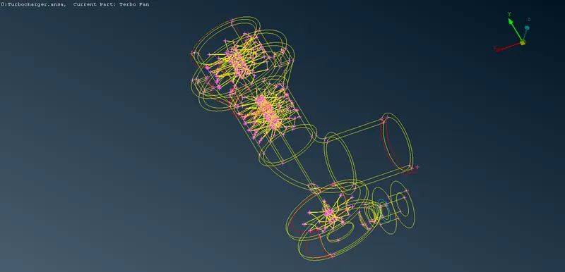
- If the red cones are present in the geometry then use TOPO-->Faces-->New-->COONS to patch the gap
- If Blue cones are present in the geometry then check for overlapping of surface, if found then delete that extra surface. In case the blue cones are necessary or justified then leave it as it is.
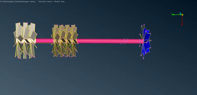
- As we are going to perform volumetric mesh we need the rotor shaft as a single volume. So, we will eliminate all the Blue cones present on the shaft except on its interface with the compressor and turbo casing.
Step 2: PID Allotment
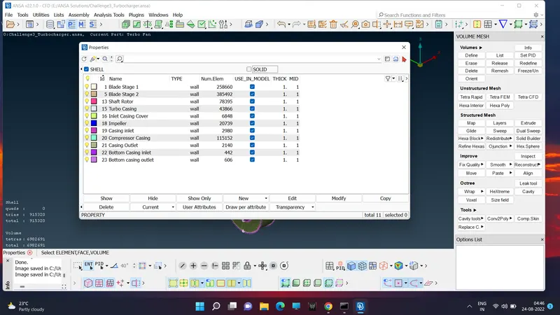
- After Geometry Clean up PID must be allocated with a meaningful name in order to make the process of selection easier.
- As Already PID has been allocated by ANSA our only task is to rename the PID for respective parts.
Step 3: Surface meshing
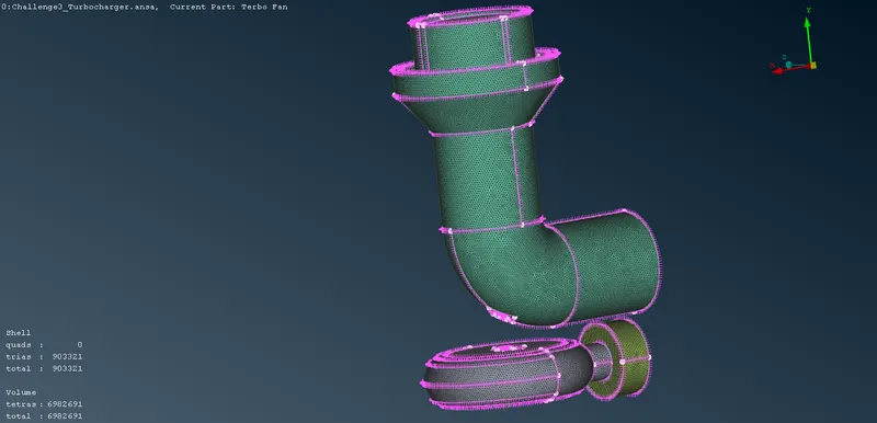
- MESH-->Perimeters-->Length-->perimeters and Macrons. In Perimeters and Macrons, Length is assigned a value of 5mm after selecting the Turbo casing, Compressor casing, and inlet casing cover.
- Mesh Parameters-->Target Length = 5, Minimum Target Length = 3
- Mesh Quality-->Min Length = 3, Max Length = 7
- MESH-->Mesh Generation-->Spot Mesh after clicking it Select the Parts mentioned above and press the middle mouse button.
- MESH-->Perimeters-->Length-->perimeters and Macrons. In Perimeters and Macrons, Length is assigned a value of 2mm after selecting the Impeller.
- Mesh Parameters-->Target Length = 2, Minimum Target Length = 1
- Mesh Quality-->Min Length = 1, Max Length = 3
- MESH-->Mesh Generation-->Spot Mesh after clicking it Select the impeller and press the middle mouse button.
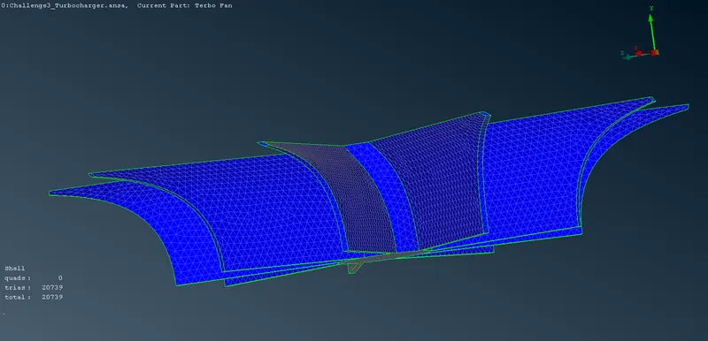
- MESH-->Perimeters-->Length-->perimeters and Macrons. In Perimeters and Macrons, Length is assigned a value of 1mm after selecting the Blade stage-1, Blade stage-2, and rotor shaft
- Mesh Parameters-->Target Length = 1, Minimum Target Length = 0.5
- Mesh Quality-->Min Length = 0.5, Max Length = 2
- MESH-->Mesh Generation-->Spot Mesh after clicking it Select the Parts mentioned above and press the middle mouse button.
- Caution: At the trailing part of rotor shaft mesh avoid assigning values in perimeter and macrons as it is the interface of mesh transition from target length 1mm to 2mm.
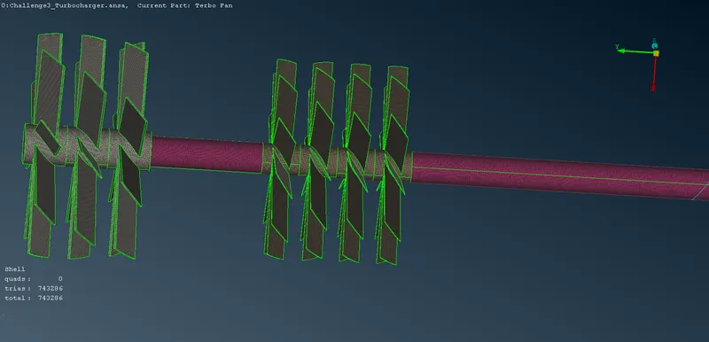
Step 4: Volume meshing
- VOLUME MESH-->Volumes-->Define--> Detect on Whole db
- A list of volumes will appear. Delete the unwanted volumes like thickness of the model, volume occupied by shaft rotor combination.
- Then select VOLUME MESH-->Unstructered mesh-->Tetra CFD and select entire model.
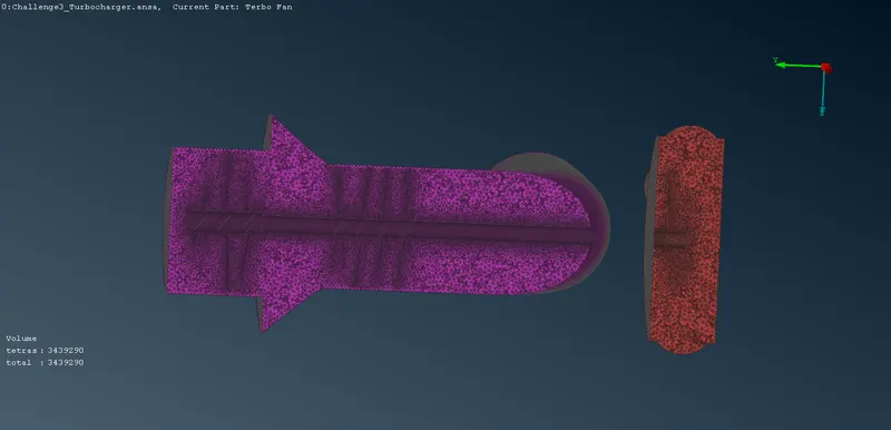
Learning Outcomes:
Learned to create Volumetric mesh(Tetra CFD).
Result:
Volume mesh has been created in the required volumes of the Turbocharger.
NOTE: unable to upload the file due to its large size.