Week-3 Challenge: ADVISOR Tool
AIM:-
To Simulate the Gradeability and Drive Cycle using ADVISOR TOOL in MATLAB
PLATFORM USED:-
MATLAB- TOOL ADVISOR
Software – Microsoft Office Excel.
SYSTEM SPECIFICATIONS:-
- Manufacturer – Acer
- Model – ASPIRE E1-531
- Operating System – windows 7 Ultimate
- Processor – Intel(R) Pentium(R) CPU B960 @ 2.20GHz 20GHz
- RAM – 4 GB
THEORY :-
ADVISOR, NREL’s ADVANCED VEHICLE SIMULATOR, is a set of Model, data and Script text file for use with MATLAB and SIMULINK. It is designed for Rapid Analysis of Performance and Fuel economy of Conventional, Electrical and Hybrid Vehicles. ADVISOR also provide a backbone for the detailed simulation and analysis of user defined Drivetrain components, a Starting point of verified vehicle data and algorithms from which to take the full advantage of the modeling flexibility of Simulink and Analytic power of MATLAB. The Model in ADVISOR are mostly empirical, relying on Drivetrain components input/output relationship measured in the Laboratory, and quasi-static, using the data collected in steady state (for example , constant torque and speed) tests and correcting them for transient effects such as the rotational inertia of Drivetrain components.
ADVISOR was preliminarily written and used in November 1994. Since then, it has been modified as necessary to help manage the US DOE Hybrid Vehicle Propulsion System subcontracts. Only in January 1998 was a concert development effort undertaken to clean up and document ADVISOR. Since then, over 4500 individuals have downloaded one or more version of ADVISOR, including all of the OEMs and major suppliers. About 2/3 of the user are from Industry and 1/3 are from Universities. A short list of major ADVISOR users includes DaimlerChrysler, FordMotor Company, General Motor Corp, Delphi Automotive Systems, TATA , Mahindra, Visteon and hundreds of others.
MAJOR COMPANIES WHICH SE ADVISOR TOOL ARE:
- Daimler Chrysler.
- Ford Motor Company.
- General Motors Corp.
- Delphi Automotive systems.
- Visteon.
HOW TO LAUNCH ADVISOR TOOL?
- Dowload the advisor tool from the following link https://sourceforge.net/projects/adv-vehicle-sim/
- Then extract the file the drive where you save file (in my case i saved in D drive apart from C drive)
- Now extract the dowloaded file in D drive and close the folder
- Now, open MATLAB Navigate the loaction of folder where your Extracted file is kept
- After navigating it in Matlab, on the Left most side of the matlab command window Navigation tree will appear , go to your extracted Folder in tree and now Right click on the Folder and Select "Select sub-folder, Add path".
- After this MAtlab now can read your dowloaded ADVISOR after navigating and adding path
- Now simply in Command window type "ADVISOR" and hit Enter advisor tool will now get open.
ADVISOR Tool have 3 Windows:-
- Vehicle Input Window.
- Simlation Parameter window.
- Result window.
OBJECTIVE:-
- To change the default value of Cargo mass value to 500kg for Ev-defaults_in file in ADVISOR Tool, with keeping all other default condition to find out whether the Vehicle can travel 45km with FTP Drive Cycle.
- For the Same above Case, now to change the battery condition and run the simulation.
- To perform Gradeability test on PRIUS_jpn_defaults_in file.
STUDY-1
- To change the default value of Cargo mass value to 500kg for Ev-defaults_in file in ADVISOR Tool, with keeping all other default condition to find out whether the Vehicle can travel 45km with FTP Drive Cycle.
DriveTrain Selection
From the DriveTrain Popup menu you will be able to select the Drivetrain configuration of the vehicle (Series, Parallel, etc.) which will cause the schematic of the vehicle configuration in the left portion of the figure to change accordingly. This will also modify which components are available for the type of Drivetrain chosen.
Selecting Components
After selecting the Drivetrain configuration, all the components of the vehicle can be selected using the popup menus, or by clicking on the component in the picture. To the left of the component popup menu is a Push-button that will allow you to add or delete components by selecting their corresponding listed m-files. The m-file of the specific component can be accessed for viewing or modifying from either the component pushbutton or by clicking on the component of the picture. The m-file of a specific component can be accessed for viewing or modifying from either the component pushbutton or by clicking on the component of the picture.
- For EV_defaults_in file, if the Cargo Mass is 500 kg with all other defaults condition, can the Vehicle travel for 45 km with FTP Drive Cycle?
Conclude your Observation.
SIMULATION EXPLAINATION:-
- In ADVISOR Tool there are various Simulink Models of car are present that based on IC Engine, Electric Vehicle and Hybrid Vehicle, By using this tool many results are obtain as Output called simulation of Vehicle.
- A change of value of Motor, Generator, Battery capacity and some other Vehicle parameter are made by ADVISOR Tool output are obtained by run option. That dialogbox are shown below,
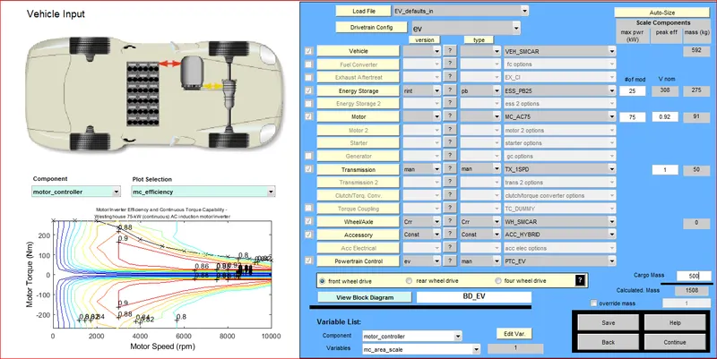
- 1st when the ADVISOR tool opened, we have to select unit to be “Metric” and then from dropdown menu in “ Load File” bar
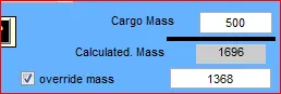
- In the above figure we can observe that the Default “Cargo Mass” is 136kg, now this value will be changed to 500 kg and then “Continue” option is clicked
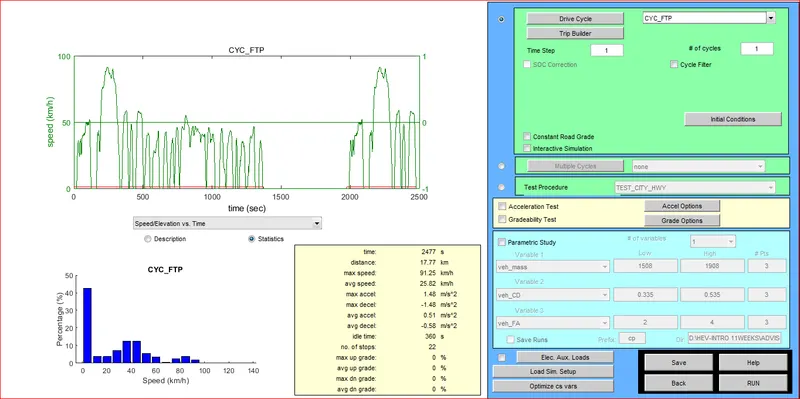
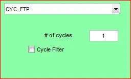
- Once we click on the “Continue” option we get a window like above figure. Here we can see that by default in the Drive Cycle bar “CYC_UDDS” is selected. So, we have changed this to “CYC_FTP” from the dropdown menu in Drive cycle bar.
- In step 1 the number of cycle is assumed as 1 for observe the distance of default vehicle travel through the inbuilt battery power.
7.Now click on the “Run” option (downwards right corner) to run the Simulation
Drive Cycle Selection
If the Drive cycle radio button is selected you can use the pull down menu to select from a list of available driving cycle. You can then select how many times you want the cycle repeated as well as if you want SOC (state of charge) correction. Initial condition can also be set from here. The filtering allows you to smooth out the selected drive cycle
Trip Builder
A cycle can be created by combing many different cycles back to back using this functionality. This new cycle is then saved in the normal cycle format and cane be run as such
Cycle – I
Let us consider the mass value as 500 kg and number of cycle as 1 then run the program. Results are obtained as graphical representation and result figure.
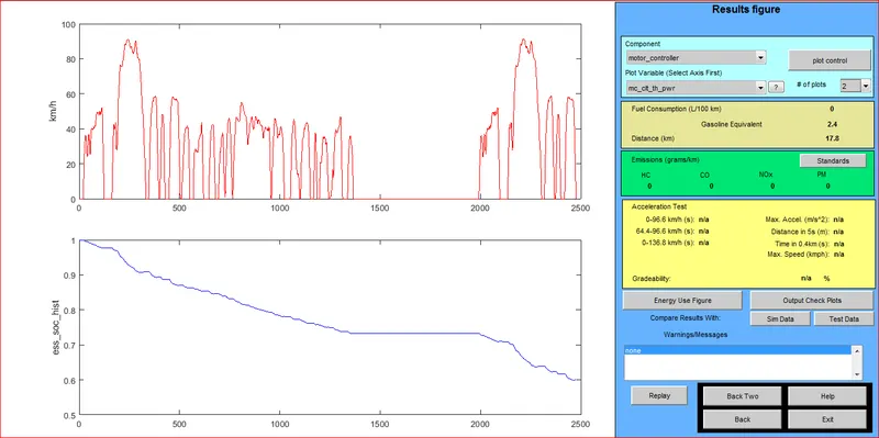
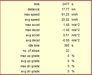
A Distance travel of vehicle is obtained as 17.8 km and the battery is drained in that state due to the capacity of power from battery. Graph represents the flow of battery and the number of Drive cycle acceleration.
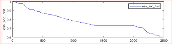
This plot shows power supply of battery to the Vehicle from initial stage to final stage.
Cycle – II
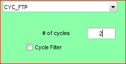
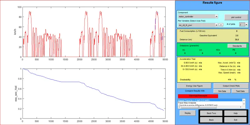
In cycle 2 the same Mass value is taken and cycle time is increased as 2 the driven acceleration of vehicle is increased so, Distance travel of vehicle increased as 35.5km.
Result figure of cycle 2 are shown as below,
Cycle – III
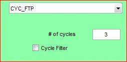
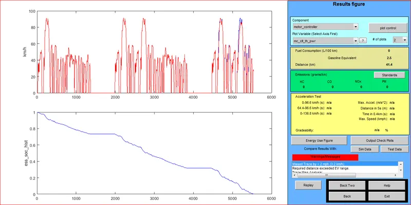
Let us take same value of mass and increase the cycle time as 3 and run the tool. In this drive cycle the vehicle travel distance is increased compared to cycle 2, it is increased as 41.4 km and the velocity of vehicle is raised by number of drive cycle.
Result figure of cycle 3 are shown as below,
Cycle – IV
Same mass and battery capacity is taken and cycle time is increased as 4.
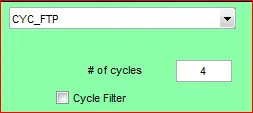
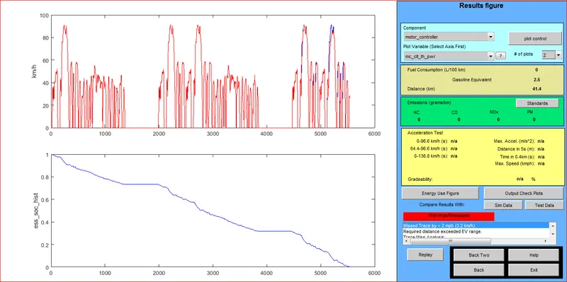
Run the Model and the results obtained from the result figure as 41.4km. This vehicle travel distance is same as that of cycle 3, here we observed that the cycle 4 are not acted because of insufficient power from battery, After completion of Cycle 3 battery will drained and vehicle will travel only that much of distance.
EMISSIONS:-
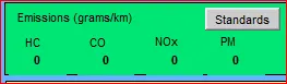
There will be Zero Emission are obtained in this model because of EV-Vehicle no combustion process is acting on engine. Battery will generate power to engine.
In Battery the Chemical energy is converted into electrical energy and produces the power from it.
OBSERVATION:-
By the observation of three-Cycle, this model the vehicle couldn’t travel for 45 km with FTP drive Cycle. The maximum distance travel in default model is 41.4 km. the maximum distance travel in the default model is 41.4 km. this maximum distance travel of vehicle is obtained only by increasing the number of cycle.
Cycle – III is the maximum number of cycle which the battery capacity is capable of acceleration. The battery is drained in number of cycle time is 3, So the Vehicle travel for 45km with FTP drive cycle is not possible by the default condition.
STUDY – 2
- In above case, try changing the battery capacity and repeat the simulation.
- In this study the same default condition are taken that are initiate in question 1 and battery capacity will be changed for accelerating the vehicle that will increase the vehicle distance travel km.
- ESS_PB 25 batteries are used in this model we want to increase the battery power to obtain more vehicle travel distance.
- Here the max power is increased as 27 instead of default value 25 then select the continue option.
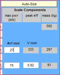
- Number of drive cycle is assigned as 3 by executing with same as working in the study – 1.
- Now run the model, here cycle time is increased with 3 times for so that velocity of vehicle also increased during driven cycle. Graph shows the variation of velocity and battery capacity
- It runs in certain distance while the power is provided from battery. While the power of battery is drained a vehicle remains stopped.
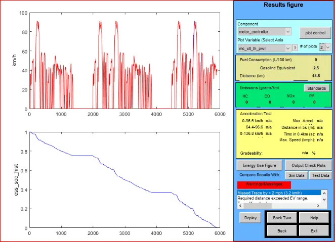
- Result figure shows that vehicle travel distance as 44.8 km that is near to 45 km
Hence by increasing the battery power the acceleration of cycle also increases that lead to more distance travel from vehicle.

STUDY - III
- Perform Gradeability test with PRIUS_Jpn_defaults_in file compare your results in table and conclude.
Gradeability Test
If the Gradeability checkbox is selected, a Gradeability test will be run in addition to chosen cycle. The grade displayed in the results figure will be the maximum grade maintainable a5t the input mph.
EXPLANATION OF STUDY:
- To Perform Gradeability test with load file of PRIUS_Jpn_defaults_in that are initiate in question, there are two type of test observed in the Gradeability.
- Gradeability test by changing the speed.
- Gradeability test by changing Grade and Speed.
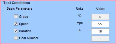
STEP-WISE Explanation:-
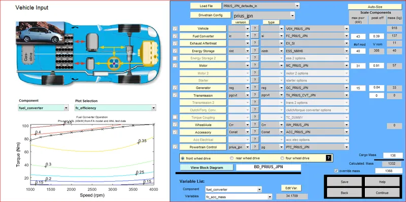
- To perform Gradeability test on the “PRIUS_ jpn_defaults _ in” file, 1st from the Dropdown menu of “Load File” bar we have selected “PRIUS_ jpn_defaults _ in” file.
- Then keeping all the default value of the parameters, we have clicked on the “Continue” option.
- Then, in the next window we can observe that there are two options “Acceleration Test” & “Gradeability Test”, since we need only the Gradeability test, we have ticked on “Gradeability Test”.
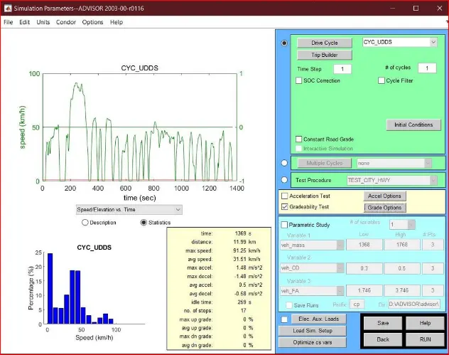
- We can also observe that there is an option adjacent to “Gradeability Test” named as “Grade Option”. By clicking on this we get the following options.
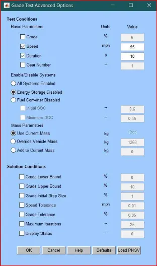
- Here we can observe the test conditions; here we can adjust the parameter according to our requirement and then run the test. Here we can set the Gradeability of the vehicle, Speed of the vehicle when that particular Gradeability is there and till how much time that Gradeability is present
- By keeping the rest value as default we then RUN the Simulation and got the following results:-
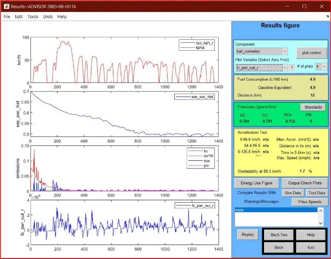
- Above figure shows the results of the Simulation, Where we can see that the Gradeability at 88.5kmph speed is 1.7 %.This tell us that only 1.7% of Gradeability can only be achieved by the vehicle at the speed of 88.5kmph.
- Since our Grade value is set to 6 % by default in the “Grade Option” menu but we got only 1.7% . This means that we have got lesser value than our desired value.
- Now let us RUN a Simulation by changing the value in the “Grade Option” menu and then observe the results.
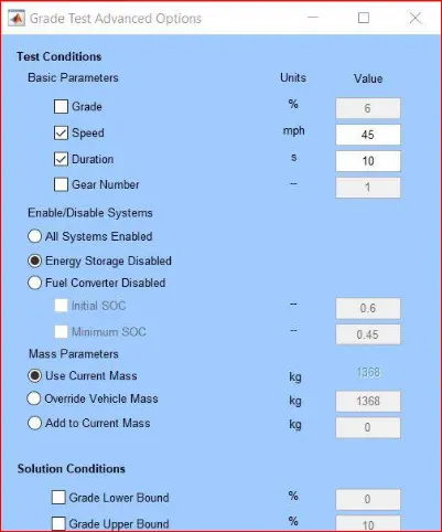
- Above results are obtain by changing the speed value in “Grade Option” menu. Now we can observe that the maximum possible Gradeability is more than the previous simulation that is 2.2% but the maximum speed has decreased.
- Now let us RUN the simulation further by changing the value in “Grade Option” menu and compare the results with previous simulation results.
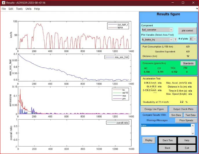
- In the above results we can see that as further we decrease the speed in “Grade Options” the Gradeability of Vehicle has increased.
- The reason for this change is, when a vehicle is travelling at high speed it require more power and adding to this if it needs to climb a slope at high speed further more power is required. Here in this study case our power amount is fixed, if the Gradeability and Speed requirement is high we cannot get desired results as power is not sufficient.
- Therefore, if the speed is at optimum value (usually 30 kmph to 60 kmph) a decent Gradeability can be achieved and if we need further more Gradeability we have to increase the power Output of Engine or Battery.
- So, in this case at 48.4 kmph we get the maximum possible Gradeability.
|
Speed in kmph |
Gradeability in % |
|
160.9 |
N/A |
|
144.8 |
0.3 |
|
128.7 |
0.3 |
|
120.7 |
0.7 |
|
88.5 |
1.7 |
|
72.4 |
2.2 |
|
48.3 |
2.5 |
|
40.2 |
N/A |
- The above table shows Gradeability of Vehicle at different Speeds. Here we can observe that at higher speed there is no Gradeability achieved with the total available power and similarly at lower speed also there is no Gradeability achieved with the total available power as at lower speed more Torque is required.
CONCLUSION :-
1. Thus, all objectives were achieved Sccessfully.
2.Similar kind of Approach can be used to study similar kind of Simulation.
3.when vehicle speed increases there is decrease in gradeability for both 10 sec and 20 sec duration.