Week 3 Challenge
1.1) Primary Load Cases to be considered for Design -
i) The Primary Load cases are -
A) Dead Load
B) Live load
1.2) What is One – Way slab?
i) If the ratio of Ly/Lx ( Ly = Shorter direction , Lx = Longer direction ) is greater than or equal to 2 , then we classify it as a One way slab
ii) In one way slab bending is along in one direction only.
iii) In one way slab main reinforcement is provided along the shorter direction because when load is applied it will distributed quickly to the
shorter span
iv) A distribution steel is provided to provide resistance against temperature and shrinkage .
v) Eg of one way slab is Slab over the Toilets , Cantilever slab etc
1.3) What is the value of unit weight of structural steel and soil?
i) The unit weight of a structural steel is 7840 kg/m^3
ii) The unit weight of soil is 18 kN/m^3
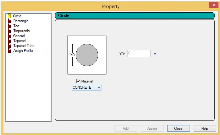
1.4) Name few sections that can be defined using Properties tab in STAAD Pro.
i) In staad pro advance we can define following sections to the model
ii) Circular section for columns
iii) Rectangular Sections for beams and column
iv) Tee Section
v) Tapered I section
vi) Tapered Tube
1.5) Define Primary Beams.
i) Primary beams are defined as the beams which are supported on columns on both the sides .
ii) This beams directly transferred the load to the columns.
iii) Primary beams rest on column which can be fixed support or any other support .
2.1) State the factors and parameters that influence the design pressure intensity of a high-rise building.
The factors and Parameters influence the design pressure Intensity as per IS 875 part 3
1) Design wind speed -
Vz= Vb K1 K2 K3 K4
where ,
Vb=Basic wind speed (m/sec)
K1=Risk coefficient (Table 1 of IS 875 (Part 3)-2015)
K2 = Terrain Roughness and height factor
K3=Topography factor (Clause 6.3.3 of IS 875 (Part 3)-2015)
K4 =Importance factor for Cyclic Region
2) Design wind pressure (pd) -
pd= Kd Ka Kc pz
where
Kd= Wind directionality factor
Ka=area averaging factor
Kc = Combination factoras
3) The wind pressure pz at any height z is given by -
Pz= 0.6 Vz^2
where
Pz= Design Wind speed in N/m2 at height z
Vz= Design wind speed in m/s.
2.2) Mention the load transfer process of a Reinforced Concrete Building.
The load transfer process of a reinforced concrete building is
i) Slab - The load will be transferred from Slab to Primary Beams
ii) Secondary beam - If Secondary beams are provided its load transferred to the Primary beams
iii) Primary beam - The loads from Primary beams to Columns
iv) Columns - The loads from Column to the Foundation
v) Foundation - Foundation transferred the load to the soil beneath the footing .
3.1) Differentiate One-Way and Two way slabs. Elaborate each slab type.
|
Sr No. |
One Way Slab |
Two Way Slab |
|
1 |
The one way slab is supported by a beam on two opposite side only. |
The two way slab is supported by the beam on all four sides. |
|
2 |
In one way slab, the load is carried in one direction perpendicular to the supporting beam. |
In two way slab, the load is carried in both directions. |
|
3 |
One way slab rest on two opposite side support beam /wall |
Two Way Slab rest on four side beam /wall . |
|
4 |
One way slab is bend only in one spanning side direction while load transfer |
Two way slab is bend both spanning side direction while load transfer |
|
5 |
In One way slab the crank is provided in one direction |
In two-way slab, the crank is provided in four directions. |
|
6 |
If L/b the ratio is greater than or equal 2 or then it is considered a one-way slab. |
If L/b the ratio is less than 2 then it is considered a two-way slab. |
|
7 |
The deflected shape of the one-way slab is cylindrical. |
Whereas the deflected shape of the two-way slab is a dish or saucer-like shape. |
|
8 |
Chajja and Varandha are practical examples of one-way slab. |
Whereas two-way slabs are used in constructive floors of the Multistorey building. |
|
9 |
In one-way slab quantity of steel is less. |
In two-way slab quantity of steel is more as compared to the one-way slab. |
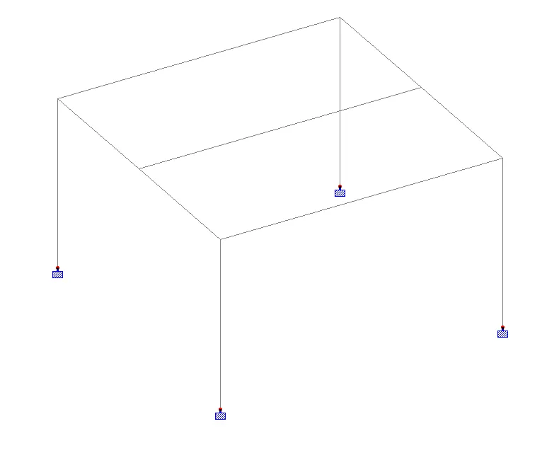
3.2) Explain the concept of secondary beams with proper sketch.
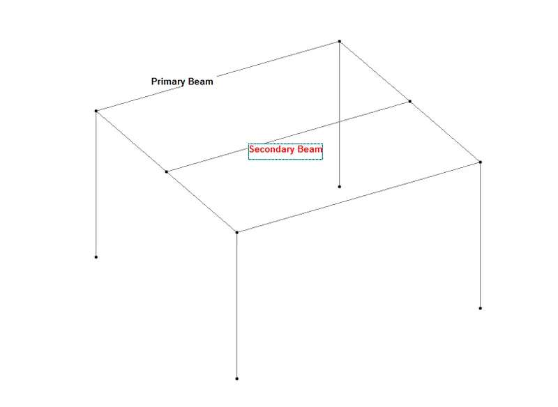
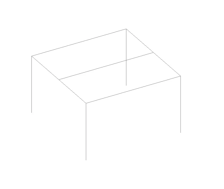
i) From the above Sketch we can see that What is Primary beams and Secondary Beams
ii) Secondary beams are the beams which runs between primary beams or we can say that they rest on primary beams
iii) In normal case loads transferred will be Slabs - Primary beam - Columns - Foundation
iv) But Incase of Secondary beams , Primary beams carry the loads coming from Slab as well as Secondary beams i.e
Slabs - Secondary Beams - Primary Beams - Columns - Foundations
v) The Secondary beams rest on simply supported
vi) As the secondary beams are simply supported the moment will be developed at the support
vii) So therefore my secondary beams should get support from our primary beams with zero moment at the ends
viii) So therefore we have to give moment releases to the secondary beams .
3.3) Mention the Primary load cases.
a) State the Indian Standards for each load case -
i) Dead load - IS 875 part 1
ii) Super Imposed Dead Load - IS 875 part 1
ii) Live Load - IS 875 part 2
b) Detail the parameters of each load case -
i) Dead load - a) Weight of structure
b) It remains constant
c) Volume of the section
ii) Super Imposed Dead Load - a) Floor Finishes
b) Service load
iii) Live Load - a) It is based on usage , occupancy etc .
b) building type residential building ,
c) commercial building
d) industrial building etc
c) Brief each load case -
i) Dead Load - i) Dead load is generally considered as self weight of the structure .
ii) This loads are constant loads which are not going to change throught the life span of structure .
iii) DL of each structural member can be calculated by multiplying L x B x D X Density of concrete
ii) Live Loads - i) Live lods are not constant throughout the life span of structure
ii) It may vary depends upon usage , occupancy etc
iii) It may also vary depends upon the type of building such as residential , commerecial , Industrical etc
iv) For Residential Builidig we assumen LL as 3Kn/m2
3.4) Detail the steps involved in assigning Properties and Support to a model using STAAD Pro sequentially.
To assign the properties follow the step -
A) For Properties
i) Once geometry is created
ii) Click on Properties -
iii) Click on Define materials
iv) Select the sections whichever you want for eg Rectangular Circular etc
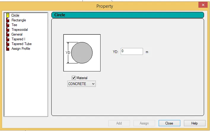
v) Once the section is selected enter the section properties like width depth or dia etc
vi) Select the materials like Concrete , Steel etc
vii) Select the beam or column and Assign it to selected beams .
B) For Support -
i) Create a two nodes using Grid / coordinate system option
ii) These nodes denotes the end of the beam
iii) Select the nodes by using Node cursor
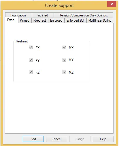
iv) Go to Support
v) Click on create - and select the Fixed support
vi) and Assign it to the selected nodes
3.5) Brief the steps to be followed to create and assign secondary beams in STAAD Pro
Procedure -
Step 1)
i) Open the Staad Pro Software
ii) Click on Analytical Modeling
ii) Name the File and Select Metric Units
iii) Click on Okay .
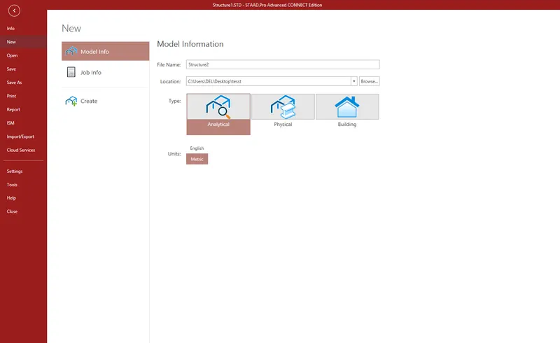
Step 2)
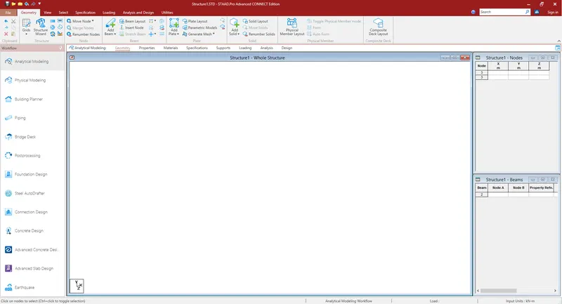
i) Once you click on Create
ii) Modal space of staad pro will open
Step 3)
i) Now Click on Grid - Beam Grid
ii) Specify the First Node point as (0,0,0)
iii) Copy that node and paste it at a distance of 10m in x direction
iv) Select these nodes by Node cursor and paste in at a distance of 10m in Z direction
v) Connect all the nodes by Beams

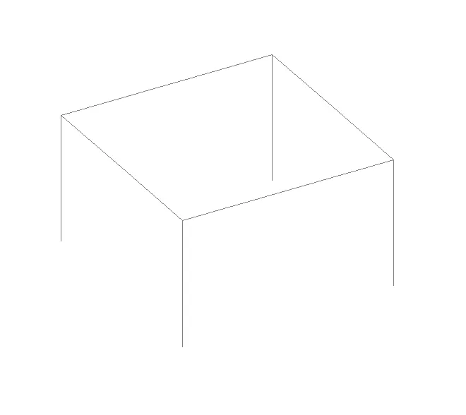
Step 4)
i) Select the nodes by using Node cursor
ii) and paste it in - Y direction at a distance of 6m
Step 5)
i) Now we have to draw the Secondary beam
ii) Right Click on screen and You will see the option of Insert node
iii) Click on Insert node - Add nodes at midpoint
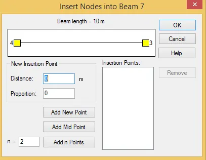
iv) Click on Add Beam - Select beam Perpendicular intersections -
Step 6)
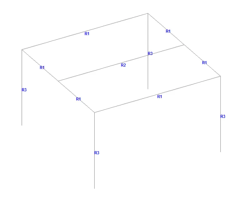
i) Once geometry is created
ii) We have to assign the properties
iii) Define the properties - Select Rectangular Section
iv) Assign it to the beams
Step 7)
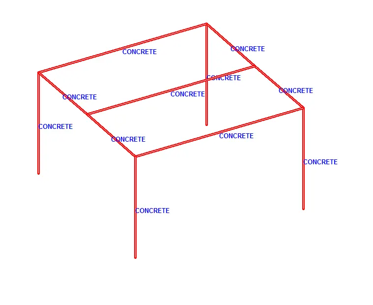
i) Assign the material as Concrete
ii) Click on Materials - Concrete and Assign it to view
Step 8)
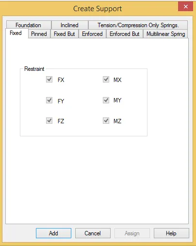
i) For Support
ii) Select the Bottom Nodes by Node Cursor
iii) Click on Support
iv) Click on Create
v) and Select Fixed Support
vi) Assign it to Selected Nodes
Practical -
1. Calculate the wind pressure for the given building
a. Building Dimension : 20m x 30m x 20m height RCC
b. Building usage : Hospital block in city centre
c. Location : Darjeeling
Step 1) Design Wind Speed
We know that
Vz = Vb x k1 x k2 x k3 x k4
where ,
Vb=Basic wind speed (m/sec)
K1=Risk coefficient (Table 1 of IS 875 (Part 3)-2015)
K2 = Terrain Roughness and height factor
K3=Topography factor (Clause 6.3.3 of IS 875 (Part 3)-2015)
K4 =Importance factor for Cyclic Region
AS Vb = 47 m/s ( Darjeeling ) Is 875
K1 = 1 (given)
K2 = 1.12 ( Ht for 20m) ( Category 1)
K3 = 1
K4 = 1
Therefore ,
Vz = 47 x 1 x 1.12 x 1 x 1
= 52.64 m/s
ii) Wind Pressure = Pz
Pz = 0.6 x Vz ^2
= 0.6 x 52.64 x 52.64
= 1662.58 N
= 1.66 Kn
Similarly we can calculate for different heights
| Height (m) | k2 | Vz (m/s) | Pz | Pz in kN |
| 3 | 1.05 | 49.35 | 1461.25 | 1.46 |
| 6 | 1.05 | 49.35 | 1461.25 | 1.46 |
| 9 | 1.05 | 49.35 | 1461.25 | 1.46 |
| 12 | 1.06 | 49.82 | 1489.22 | 1.48 |
| 15 | 1.09 | 51.23 | 1574.70 | 1.57 |
| 18 | 1.10 | 51.70 | 1603.73 | 1.60 |
| 20 | 1.12 | 52.64 | 1662.58 | 1.66 |
2. Calculate the Dead load and Live load for the above building with reference to IS standards ( assume suitable sections )
To Calculate Dead Load of Column , Beam , Wall and Slab are as follows -
A) For Column -
i) As we have assume Column Size as (0.5 x 0.5 )
ii) Length of column = 6m
Therefore
Dead Load = L X B X H x Unit weight of Concrete
= 6 x 0.5 x 0.5 x 25
= 37.5 KN
So Dead Load of Each Column is 37.5 KN
2) For Beams -
i) As we have assume Beams Size as ( 0.300 x 0.450 m)
ii) Length of beam = 5m
Therefore
Dead Load = L X B X H x Unit weight of concrete
= 5 x 0.3 x 0.45 x 25
= 17 KN
So Dead Load of Each Beam is 17 KN
3) For wall - As it has Block
i) Assume the Height of wall 2.8 m
ii) Thickness of wall = 0.230 m
iii) Unit weight of Blocks = 20Kn/m^3
Therefore
Dead Load = B X H x unit weight of block
= 0.230 x 2.8 x 20
= 12.88 KN / m
So Dead Load of wall is 12.88 KN /m
4) For Slab
i) Assume the thickness of slab = 200 mm
Therefore
Dead Load = thickness X Unit weight of concrete
= 0.200 x 25
= 5 Kn / m^2
Dead Load of Slab = 5 Kn/m^2
2) For Live Load - As per IS 875 Part 2
|
Sl. No. |
Description |
UDL Load (kN/m2) |
Concentrated Load (kN) |
|
1. |
Bathrooms and toilets in all types of buildings |
2 |
1.8 |
|
3 |
Office rooms in |
||
|
(i)Hostel, hotels, hospitals and business building with separate store |
2.5 |
2.7 |
|
|
(ii)In assembly buildings |
3 |
4.5 |
|
|
4. |
Kitchens in |
||
|
(i) Dwelling houses |
2 |
1.8 |
|
|
(ii) Hostels, hotels and hospitals |
3 |
4.5 |
|
|
5. |
Banking halls, class rooms, X-ray rooms, operation rooms |
3 |
4.5 |
|
6. |
Dining rooms in |
||
|
(i)Educational buildings, institutional and mercantile buildings |
3 |
2.7 |
|
|
(ii)Hostels and hotels |
4 |
2.7 |
|
|
7. |
Corridors, passages, stair cases in |
||
|
(i) Dwelling houses, hotels, and hostels |
3 |
4.5 |
|
|
(ii)Educational, institutional and assembly buildings |
4 |
4.5 |
|
|
(iii) Mercantile buildings |
5 |
4.5 |
|
|
8. |
Reading rooms in libraries |
||
|
(i)With separate storage |
3 |
4.5 |
|
|
(ii)Without separate storage |
4 |
4.5 |
|
|
9. |
Assembly areas in assembly buildings |
||
|
(i)With fixed seats |
5 |
||
|
(ii)Without fixed seats |
5 |
3.6 |
|
|
10. |
Store rooms in educational buildings |
5 |
4.5 |
|
11. |
Store room in libraries |
6 for a height of 2.24 2kN/m2 for every 1m additional height |
4.5 |
|
12. |
Boiler rooms and plant rooms in |
||
|
(i)Hostels, hotels and hospitals, mercantile and industrial buildings |
5 |
4.5 |
|
|
(ii)Assembly and storage buildings |
7.5 |
4.5 |