Week 3 Challenge
Q1
1. primary loadcase to be considered in the design
the self weight of the structure and the elements based on the material and its unit weight are considered as primary loads
these are commonly termed as deadload
2.One way slab:-
the slab which is supported on only two sides i.e., on parallel beams or parallel beam is called as one way slab
the length to breath ratio of the one way slab is greater than or equal to 2
one way slab bends in only one direction while transvering the load to the beams or walls
3.unit weight
unit weight of the structural steel = 78.5 kn/m^3
unit weight of the soil = 20 kn/m^3
4.List of sections that can be defined using the properties tab in staadpro
- circle
- rectangular
- trapezoidal
- tee
- tappered tube
5. Primary beams
the beams which are placed between the columns are called as primary beam
primary beam will transfer the load directly to the columns
Q2
1.Factors and parameters which influences the design wind pressure intensity of a high rise building
- design wind pressure = 0.6 Vz^2
Vz= design wind speed
Vz= Vb k1 k2 k3 k4
Vb= basic wind speed
K1= risk coefficient
K2= terrain roughness and height factor
K3= topography factor
K4= importance factor for cyclonic region
2. Load transfer process of reinforced concrete building
slabs> beams> columns>foundation> sub soil
Q3
1. difference between one way slab and two way slab
| one way slab | two way slab |
| slab which is supported on only two sides is called as one way slab | slab which is supported on all four sides is called as two way slab |
| length to breath ratio of the slab is less than 2 | length to breath ratio of the slab is greater than or equal to 2 |
| slab bends in only one direction | slab bends in both the directons |
| main reinforcement is provided on one direction | main reinforcement is provided on both sides to resists bending |
2. Secondary beams:-
the beam which rests on the primary beams are known as secondary beams.
the load from the secondary beams is transferred to the primary beams and not directly to the columns.
3.Primary load cases
- dead load
- live load/ super imposed load
- wind load
- seismic load
3(a).Indian standards of load case
Dead load :- the constant load that is acting upon the structure due to the self weight of structural elements, permanent objects
Live load:- the temporary load which may vary with time and space based on relocating/ moving the objects is known as live load
Wind load:- the load which acts on the exterior part of the structure due to the impact of wind is known as wind load. It depends on the wind speed and shape/ size of the structure.
4. steps involved in assigning properties and supports to the model
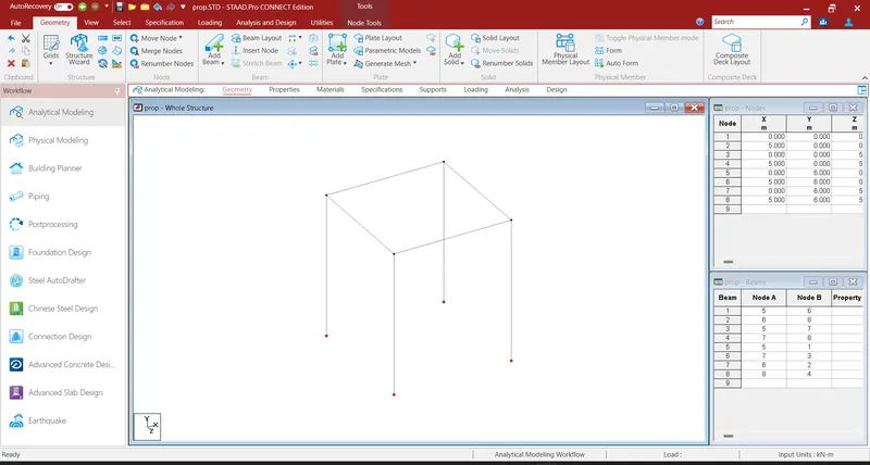
- firstly add the nodes
- then add the beams connecting the nodes
- then go to the properties
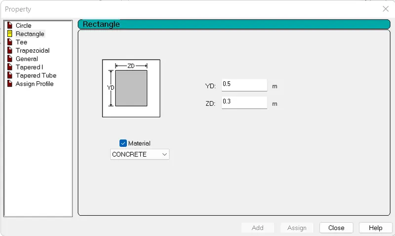
- click on the define option
- select the cross section of the element
- specify the dimensions in the dialogue box
- then click on add
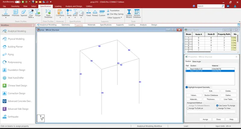
- add the cross sections and then assign them to the beams and columns.
To assign the supports
- go to supports command
- click on create option and select the type of support to be added
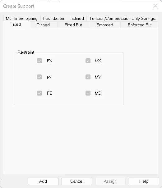
- click on add
- then assign the supports to the selected nodes
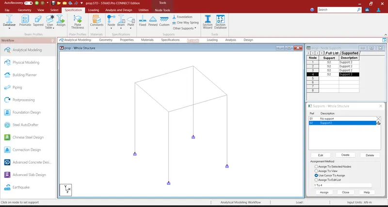
5. Steps to create and assign the secondary beams in staadpro
- firstly create nodes and add beams
- then add the nodes to draw the secondary beam
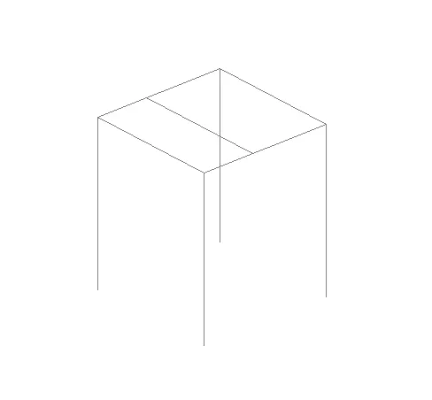
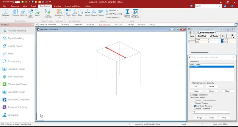
- but the staad itself doesnot it be a secondary beam it takes to be a pimary beam after the analysis is done we can see the moments transferinng from the secondary beams to the primary beams
- so to avoid the transmission of moments we need to assign the moment releases to the secondary beam
- go to the member specifications
- click on the beams
- and add the moment releases and also release the axial force of the secondary beam
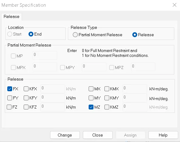
- then assign them to the secondary beam
CALCULATION OF WIND PRESSURE
Given data:-
1.dimensions of the building is 20x 30x 20m
2.Building occupancy hospital
3.location: darjeeling
Assumptions:-
- basic wind speed as 50m/s
- design life of the building as 50 years
- category of the terrain as 4
coefficients:-
- probability factor is taken as K1= 1
- Terrain coefficient is K2=1.10
- topography factor K3 =1
DESIGN WIND SPEED
Vz= Vb k1 k2 k3
Vz= 50 x 1 x 1.10 x 1
Vz= 55 m/s
DESIGN WIND PRESSURE
Pz = 0.6Vz^2
Pz= 0.6 x 55^2= 1815 N/m^2 = 1.815 Kn/m^2
CALCULATION OF DEAD LOAD AND LIVE LOAD
Given dimensions of the building 20 x 30 x 20m
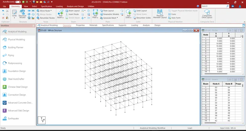
steps to create a structure:-
- firstly add the nodes as per the given dimenions 20 x 30
- add beams along x and z directions
- then select all the beams and click on translation repeat
- specify the height of the single storey and specify the no to times to be repeated
- click on link steps option and press ok
- the structure is being created
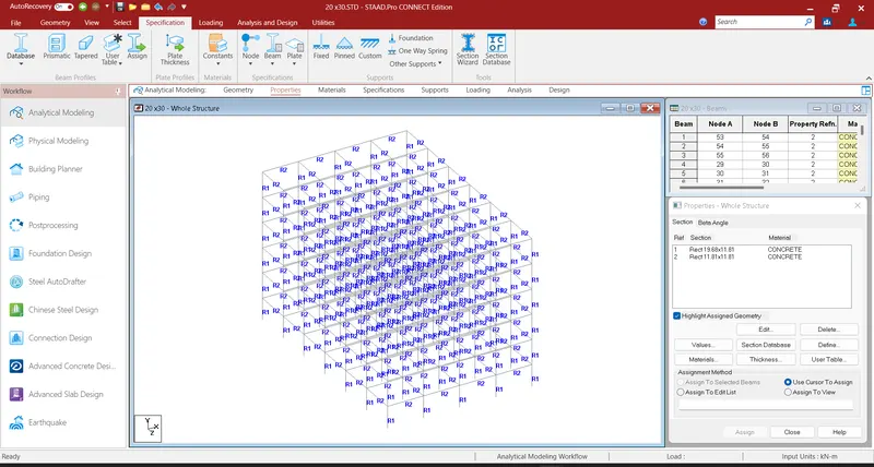
- then go to properties and define the cross sections of beams and columns
- assign the defined cross sections to the structure
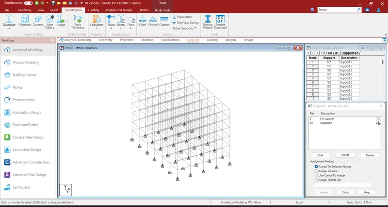
- then go to supports tab and define the type of support to be added
- then selected nodes and assign them to the selected nodes
Dead load:-
assume the unit weight of the concrete as 24kn/m^3
cross section of the beam is 0.3 m x 0.3m
self weight of the beam is 0.3 x 0.3 x 24 =2.16 KN/M
cross section of the column is 0.5 x 0.3
self weight of the column is 0.5 x 0.3 x 24=3.6 kn/m
NOTE:- the above values are for the single beam and column
multiplying the above values with number of beams and columns gives the total self weight of the structure
Live load :-
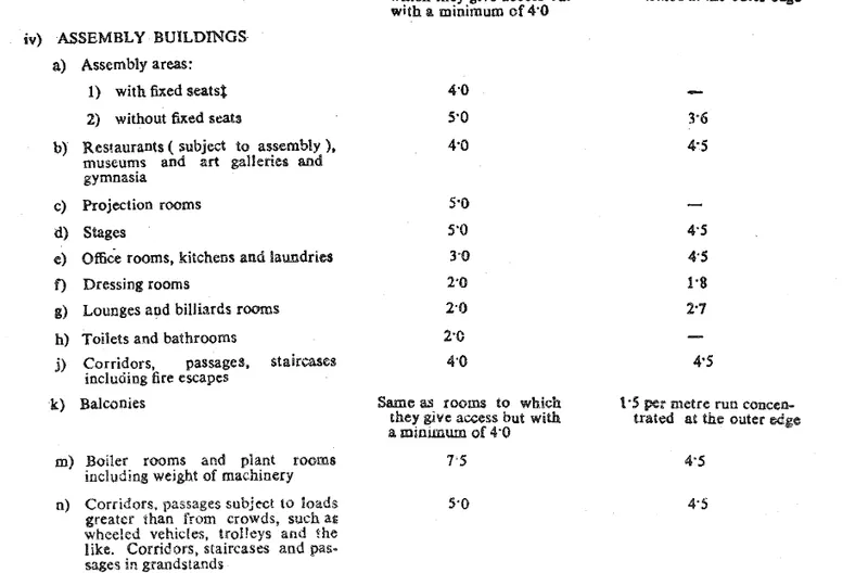
since the given block is hospital building the live load / imposed loads are obtained from IS 875 part 2 as shown below