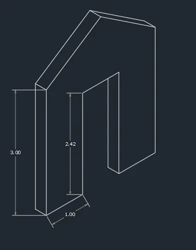
Creating a Floor plan, Footing detail and Isometric view using AutoCad
Q1.
Aim:- to sketch a cross-section of a load-bearing wall over a spread footing.
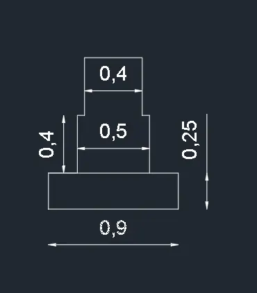
step 1:-to sketch a substructure
- take a rectangle command
- specify the first point
- specify the next point as 0.9, 0.25
- Click enter to leave a command
- then take a line command
- specify the start point at a distance of 0.2 units from the edge of the rectangle
- specify the next point as @0.4<90
- specify the next point as @0.05<0
- specify the next point as @0.4<90
- specify the next point as @0.4<0
- specify the next point as @0.4<270
- specify the next point as @0.05<0
- specify the next point as @0.4<270
- Click enter and leave the command
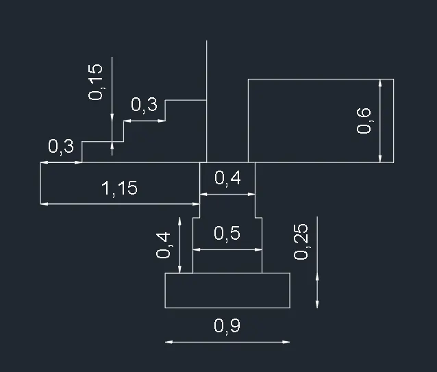
step 2:- to sketch the structure up to ground level and steps
- take a line command and specify the first point at the face of the footing on the right side
- specify the next point as @1<0
- specify the next point as @0.6<90
- specify the next point as @1<180
- close the line and press enter
- take a line command and specify the first point at the face of the footing on the left side
- specify the next point as @0.3<270
- specify the next point as @1.15<180
- specify the next point as 0.3<90
- close the line and press enter
- then to sketch the steps take a line command
- specify the first point at a distance of 0.3 from the base
- specify the next point as @0.15<90
- specify the next point as @0.3<0
- specify the next point as @0.15<90
- specify the next point as @0.3<0
- specify the next point as @0.15<90
- specify the next point as @0.3<0
- Click enter and leave the command
step 3:-to sketch a superstructure
- take a line command and specify the first point at a level of 0.6
- specify the next point as @0.3<180
- specify the next point as @0.05<90
- specify the next point as @0.3<0
- close the line
- drag 2 vertical lines up to to a height of 1 from the level of 0.6
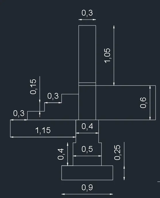
result:- the load-bearing wall on spread footing is drawn as per the required measurements.
Q2
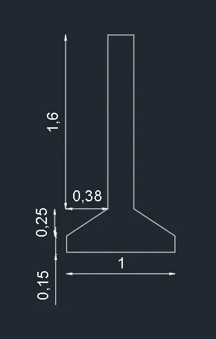
Aim:- to sketch a crosssection of isolated footing
step1:-to draw an outer line of the isolated footing
- take a line command
- specify the first point
- specify the next point as @1,0
- specify the next point as @0,0.15
- specify the next point as @-0.38,0.25
- specify the next point as @0,1.6
- specify the next point as @-0.28,0
- specify the next point as @0,-1.6
- specify the next point as @-0.38,-0.25
- specify the next point as @0,-0.15
- Click enter and leave the command
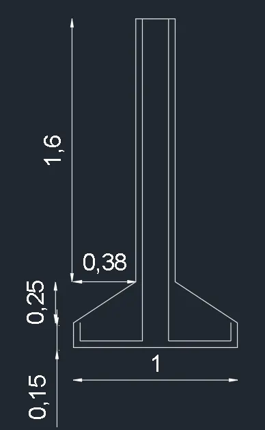
step 2:- to show the reinforcement details
- take offset command and mention a distance of 0.04
- select the line of 1 unit to be offsetted
- select the two vertical lines of length 1.6 to be offsetted
- select the two vertical lines of length 0.15 to be offsetted
- then trim the lines
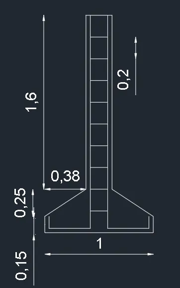
- take an offset command and mention the offset distance as 0.2
- and select the top horizontal line and copy an offset up to the bottom of the structure
Q3:
Aim:- to sketch a plan of two bedroom building
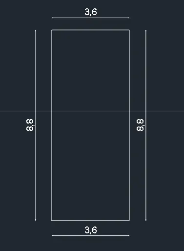
step1:- to draw an outer boundary of the building as per the dimensions
- take a line command and specify the first point
- specify the next point as @4.6<0
- specify the next point as @8.8<90
- specify the next point as @4.6<180
- close the line and leave the command
step 2:- to show the partition walls
- take an offset of line 3.6 from the top
- specify the offset distance as 3.6
- take an offset of line 8.8 from the left
- specify the offset distance as 0.9
- take an offset of line 8.8 from the right
- specify the offset the distance of 1.8
- then trim the line to provide an opening
- and erase the lines
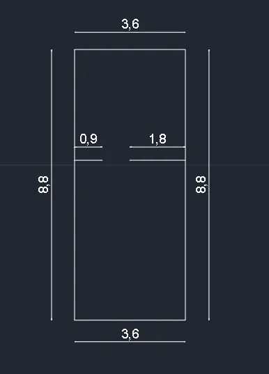
step 3:- provide steps on either side of the building
- take offset of 4.2 from the bottom
- press enter and leave the command
- take offset of 1 from the previously offset line
- trim the outer walls for providing the opening of 1 unit
- then create steps by taking an offset of 0.3 and length 1
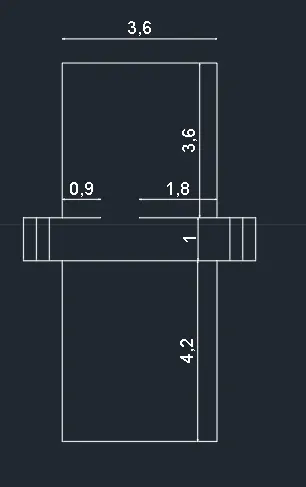
Q4
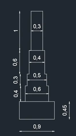
Aim;- to sketch a crosssection of load-bearing wall showing foundation details.
step 1:- to draw a PCC bed
- take a line command
- specify the first point
- specify the next point as @0.9<0
- specify the next point as @0.45<90
- specify the next point as @0.9<180
- then close the line and click enter
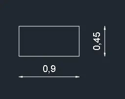
step 2:- to draw a substructure
- take a line command and specify the first point at a distance of 0.15 from the face of the PCC
- specify the next point as @0.4<90
- specify the next point as @0.05<0
- specify the next point as @0.3<90
- specify the next point as @0.05<90
- specify the next point as @0.6<90
- specify the next point as @0.4<0
- specify the next point as @0.6<270
- specify the next point as @0.05<0
- specify the next point as @0.3<270
- specify the next point as @0.05<0
- specify the next point as @0.4<270
- Click enter and leave the command
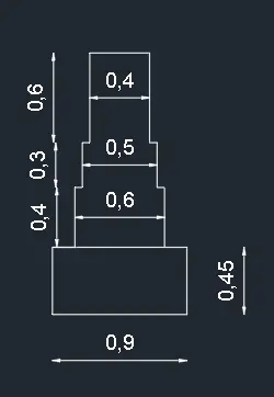
step 3:- to draw a wall over a footing
- take a line command and specify the first point at a distance of 0.05 from the face of the footing
- specify the next point as @1<90
- specify the next point as @0.3<0
- specify the next point as @1<270
- Click enter and leave the command.
Q5.
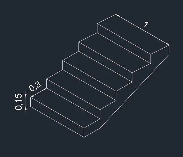
AIM:- to sketch an isometric view of the steps as per the requirements
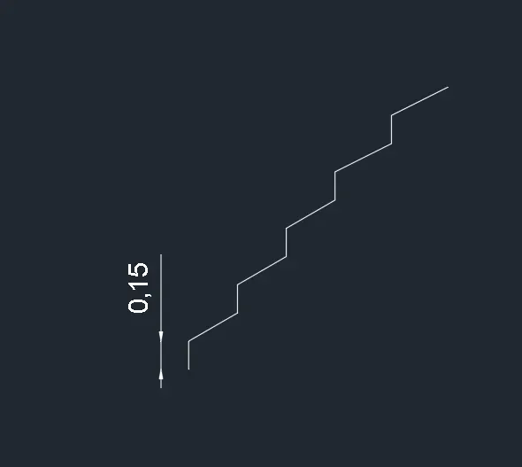
step1:- to change the drafting setting to isometric snap and create the side view of the staircase
- to change the settings enter DS command
- click the snap-type as isometric
- immediately crosshair will represent the X and Z directions
- take a line command and specify the first point
- specify the next point as @0,0.15
- specify the next point as @0.3,0
- specif the next point as @0,0.15
- specify the next point as @0.3,0
- specif the next point as @0,0.15
- specify the next point as @0.3,0
- specif the next point as @0,0.15
- specify the next point as @0.3,0
- specif the next point as @0,0.15
- specify the next point as @0.3,0
step2:-
- copy the above image at a distance of 1 unit
- take a line command and join the lines
- then the required isometric view of the staircase is done.
Q6
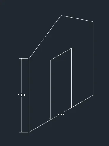
Aim:- to sketch an isometric view of gable wall
step 1:-
- change the setting to isometric snap
- then create a line diagram of the gable wall
- take a line command
- specify the first point
- specify the next point as @1,0
- specify the next point as @0,2.46
- specify the next point as @1,0
- specify the next point as @0.-2.46
- specify the next point as @1,0
- specify the next point as @0,3
- specify the inclined line
- then close the line and leave the command
Step 2:-
- take a line command
- specify the thickness of the wall as 0.3
- and join the points by taking the lines.