Drafting of various geometries using Chamfer, Fillet tool in AutoCad
Q1
Aim:- to sketch a given image using the various commands and tools
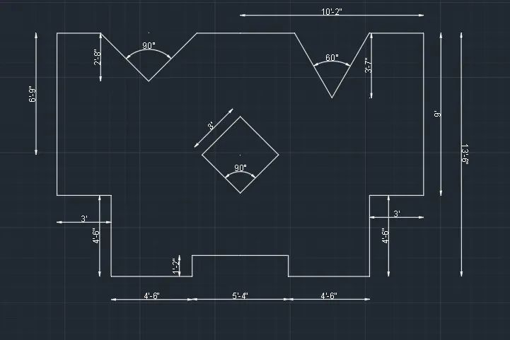
step 1:- to draw the outer lines of the image as per the above-mentioned dimensions
- take a line command
- specify the first point
- specify the next point as 3
- then change the polar tracking setting of the OS
- set the polar tracking angle as 45,9,135
- then take a line command
- specify the first point as the end of the previous line
- then orient the cursor at the angle of 135
- specify the length as 2.12
- then again orient the cursor at the angle of 90
- specify the length as 2.83
- specify the next point as 2 @0
- then join the line to the starting point of the image
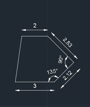
step 2:- to insert a circle of diameter 1.2
- so firstly I have created a point at the center of the circle by specifying the coordinates
- then turn on the node point in the OS settings
- then the node point will be highlighted
- then take a circle command
- specify the center at the node point
- specify the diameter as 1.6
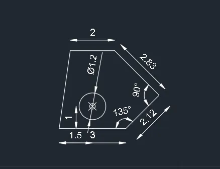
step 3:- To create a circle of diameter 0.8
- identify the center of the circle
- take a point and mark the center of the circle
- take a circle command
- specify the center at the node point
- specify the diameter as 0.8
Q2
aim:- to sketch a given image as per dimensions
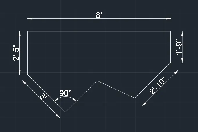
- firstly the dimensions are given in feet and inches
- so change the units to engineering-type
- and modify the primary units of dimension style as engineering type
- now take a line command
- specify the first point
- specify the next point as @1'9"<270
- specify the next point as @2'10" <225
- Click enter and leave the command
- take a line command
- specify the first point at the left corner of the horizontal line
- specify the next point as @2'5"<270
- specify the next point as @3'<315
- specify the next point as 2'6" such that it makes 90 degrees with the previous line
- then joint the endpoints click enter
Q3
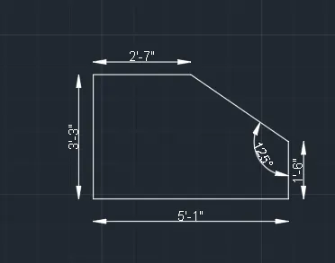
Aim:- to sketch a given image as per the requirements by using various AutoCAD tools like line, circle, polar tracking
step 1:- change the units to engineering
- give the command as un
- then select the units as engineering-type
- select the precision of the dimensions
- and insertion scale of units should be set to inches
- similarly, the primary units in the dimension style should be set to engineering-type
step 2:- to create an outer line of the given image
- take a line command
- specify the first point
- specify the next point as 2'7"@180
- specify the next point as 3'3"@270
- specify the next point as 5'1"@0
- specif the next point as 1'6"@90
- then change the polar tracking of OS
- polar tracking is set to 5,10, 15, 20.............
- then take a line command orient the cursor at an angle of 125
- then draw a line joining the start point
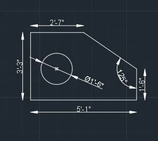
step 2:- to insert a circle of diameter 1'-6"
- mark the center of the circle
- take a circle command
- specify the center of the circle
- specify the diameter as 1'-6"
- Click enter
Q4
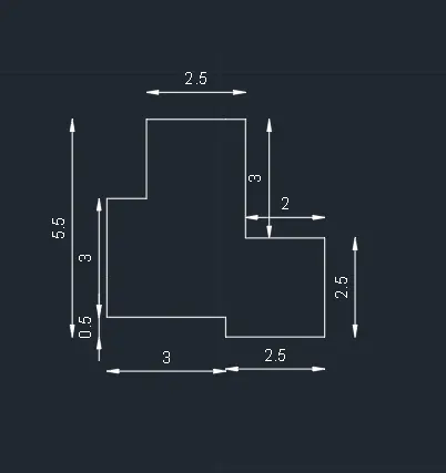
AIM:- to sketch a given image as per the required dimensions
- take a line command
- specify the first point
- specify the next point as @3<0
- specify the next point as @0.5<270
- specify the next point as @2.5<0
- specify the next point as @2.5<90
- specify the next point as @2<180
- specify the next point as @3<90
- specify the next point as @2.5<180
- specify the next point as @2<270
- specify the next point as @1<180
- then click close and enter
Q5
AIM:- to sketch a given image using the AutoCAD tools as per the required dimensions
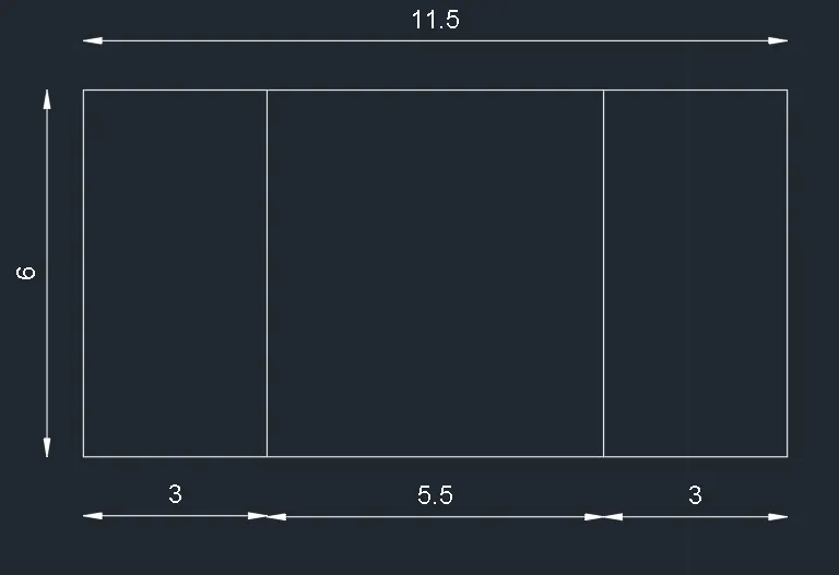
step 1:- to create an outer line of the image
- take a line command
- specify the first point
- specify the next point as 11.5<0
- specify the next point as 6<90
- specify the next point as 11.5<180
- then click close and enter
- the other two vertical lines are drawn by taking the offset
- take offset command
- specify the offset distance as 1.5
- Click on the line to be offsetted
- and click enter
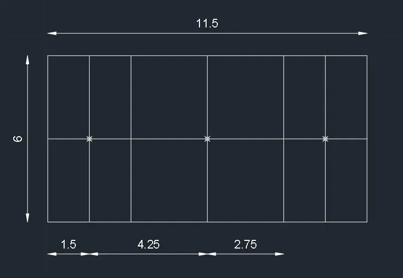
step 2:- to mark the center point of the circles
- to mark the center of the circles firstly I have drawn lines such that the intersection point is the center of the circles
- then intersection points are marked by taking nodes
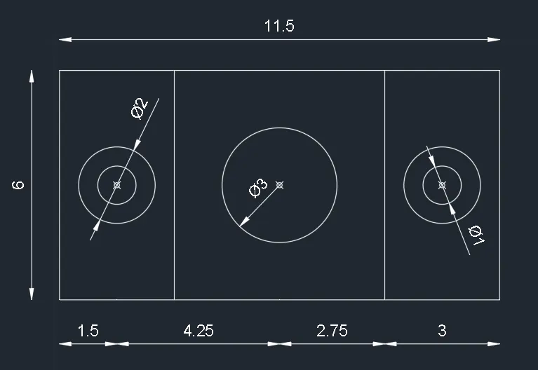
step 3:- to draw circles
- take a circle command
- specify the center point
- specify the diameter as given
- then repeat the same procedure to draw other circles also
Q6
Aim:- to sketch a given image as per the given dimensions using AutoCAD tools
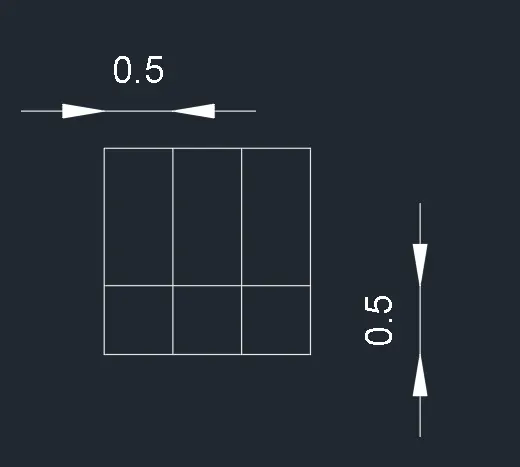
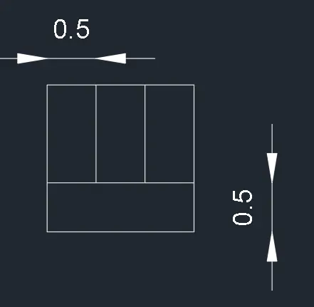
step 1:-to draw the first image
- firstly draw a rectangle of size 1.5 x 1.5
- then take offset command
- specify the offset distance as 0.5
- select the below horizontal line to offset
- next, select the vertical line to offset
- then click enter and leave the command
- take a command trim(TR)
- select the lines to be trimmed
- then click the space bar
- and trim the lines as per the requirement
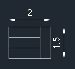
step 2:- to draw the second image
- take a line command
- specify the first point
- specify the next point as 2<0
- specify the next point as @1.5<90
- specify the next point as @2<180
- then click close and enter
- then take offset command
- specify the offset distance as 0.5
- draw offset lines
- then take a command trim
- then select the lines to be trimmed
- and click on the part of the lines to be erased
step 3:-
Q7
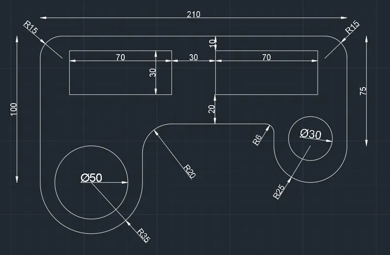
aim:- to sketch a given image as per the given dimensions using various commands
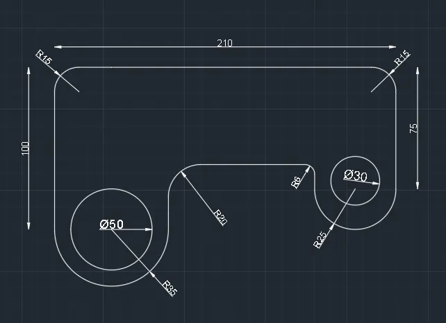
step 1:- to draw the outer line of the image and circles
- units are set to decimal
- take a line command
- specify the first point
- specify the next point @100<90
- specify the next point as @210<0
- specify the next point as @75<180
- Click enter and leave the command
- take a fillet command
- specify the radius as 15
- select the left corner lines
- and also select right corner lines
- then take start, end, center arc
- specify the points and radius to create arcs on both sides at the bottom
- then specify the circle radius and draw circles
- and also fillet the corners at the bottom by specifying the radius
step 2:- to draw rectangles
- take a line command
- specify the first point as mentioned
- specify the next point as @30<270
- specify the next point as @70<0
- specify the next point as @30<90
- specify the next point as @70<180
- similarly, draw the other rectangle
Q8
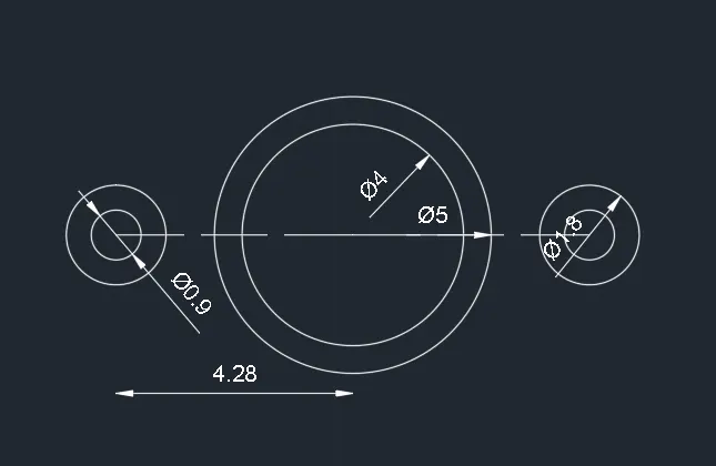
AIM:- to draw a given image as per the given dimensions
step 1:- to draw circles
- take a circle command
- specify the center point of the circle
- specify the diameter as 4
- then again take a circle command
- specify the center at the center of the previous command
- specify the diameter as 5
- then specify the center of the other two circles at the distance of 4.275 from the center of the first circle
- specify the diameter as 0.9
- again at the same center point take another circle with a radius of 0.9
- similarly draw the circles on the other side
step 2:- to draw a tangent lines
Q10
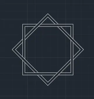
- firstly create a rectangle using polyline or rectangle from the drawing toolbar
- then take an offset of the command by specifying the offset distance
- then take a rotate command
- select a base point at the geometric center of the rectangle
- click copy to save the rotated image as the other
- rotate the image at an angle of 45
- then trim the overlapped lines to create an image
Q11
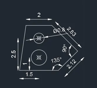
the procedure of creating the given image as per the given dimensions
- take a line command
- specify the first point
- specify the next point as 9'<270
- specify the next point as @3<0
- specify the next point as @4'6"<270
- specify the next point as @4'6"<0
- specify the next point as @1'2"<90
- specify the next point as 5'4"<0
- specify the next point as @1'2"<270
- specify the next point as @4'6"<0
- specify the next point as @4'6"<90
- specify the next point as @3'<0
- specify the next point as 9'<90
- then close
- to make a groove mark the point at the (5'1", 2'8") fom the left corner
- turn on the polar tracking and draw the lines joining the points
- to create a rhombus mark the geometric center of the rhombus
- then create a rhombus of each side 3'