Creation of geometries by Coordinate system methods using AutoCad
AIM:- to draw the geometrics given using the coordinate systems, line command, circle command in AutoCAD and write the step-by-step procedure of creating the drawing.
units should be set to decimal
the procedure of creating p1 geometry using rectangle coordinate system:-
- take a line command by entering L in the command bar
- give the start point as 2,1
- specify the next point as 8,1
- then specify the next point as 8,2
- specify the next point as 3,2
- specify the next point as 3,6
- specify the next point as 8,6
- specify the next point as 8,7
- specify the next point as 2,7
- then close and press enter to leave the command
- the required geometry is generated
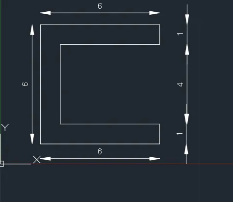
the procedure of creating p2 geometry using rectangle coordinate system:-
- take a line command by entering L in the command bar
- give the start point as 2,1
- specify the next point as 5,1
- then specify the next point as 5,5
- specify the next point as 6,5
- specify the next point as 6,1
- specify the next point as 9,1
- specify the next point as 7,8
- specify the next point as 4,8
- then close and press enter to leave the command
- the required geometry is generated
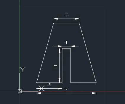
the procedure of creating p4 geometry using rectangle coordinate system:-
- take a line command by entering L in the command bar
- give the start point as 2,1
- specify the next point as 3,1
- then specify the next point as 3,5
- specify the next point as 5,3
- specify the next point as 7,5
- specify the next point as 7,1
- specify the next point as 8,1
- specify the next point as 8,8
- specify the next point as 7,8
- specify the next point as 5,5
- specify the next point as 3,8
- specify the next point as 2,8
- then close and press enter to leave the command
- the required geometry is generated
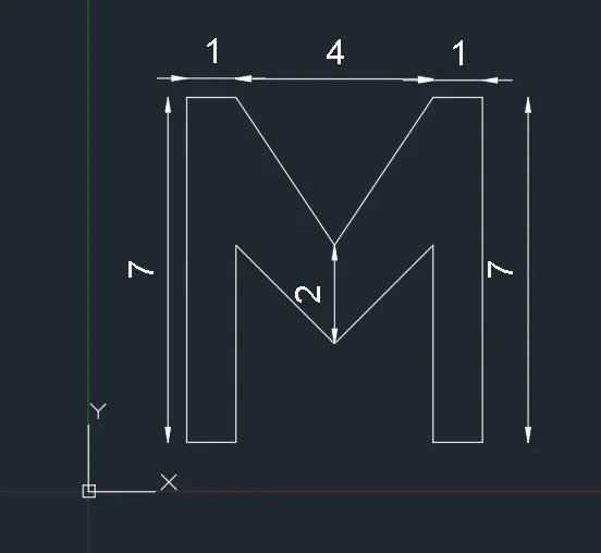
the procedure of creating p5 geometry using rectangle coordinate system:-
- take a line command by entering L in the command bar
- give the start point as 2,1
- specify the next point as 3,1
- then specify the next point as 3,8
- specify the next point as 8,8
- specify the next point as 8,2
- specify the next point as 5,2
- specify the next point as 5,1
- specify the next point as 9,1
- specify the next point as 9,9
- specify the next point as 2,9
- then close and press enter to leave the command
- the required geometry is generated
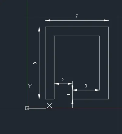
the procedure of creating p7 geometry using rectangle coordinate system:-
- take a line command by entering L in the command bar
- firstly outer rectangle is generated
- give the start point as 2,1
- specify the next point as 2,7
- specify the next point as 10,7
- specify the next point as 10,1
- then close and press enter to leave the command
- then to draw the inner rectangle 1 take line command take the start point as 3,2
- specify the next point as 5,2
- specify the next point as 5,5
- then specify the next point as 3,5
- then close and press enter to leave the command
- then to draw the inner rectangle 2 take line command take the start point as 6,2
- specify the next point as 8,2
- specify the next point as 8,5
- then specify the next point as 6,5
- then close and press enter to leave the command
- then the required diagram is generated
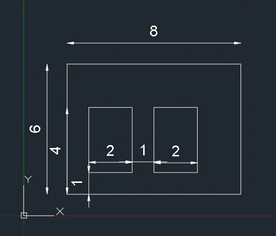
the procedure of creating p8 geometry using rectangle coordinate system:-
- take a line command by entering L in the command bar
- the given picture can be drawn easily by the direct line method
- give the start point as 0,0
- then move the cross-hair to the left o right and mention the length of the line as specified in the question
- then close and press enter to leave the command
- the required geometry is generated
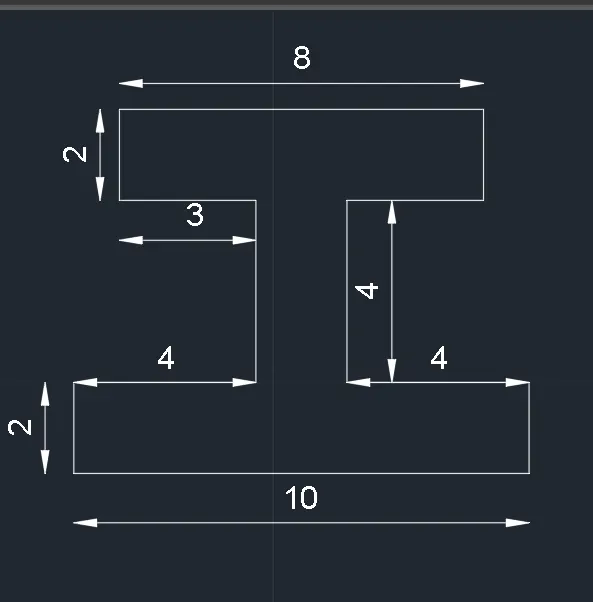
the procedure of creating p9 geometry using rectangle coordinate system:-
- take a line command by entering L in the command bar
- give the start point as 1,1
- specify the next point as 1,8
- then specify the next point as 5,6
- specify the next point as 5,4
- specify the next point as 2,4
- specify the next point as 2,2
- specify the next point as 3,2
- specify the next point as 3,3
- specify the next point as 6,3
- specify the next point as 6,1
- then close and press enter to leave the command
- the required geometry is generated
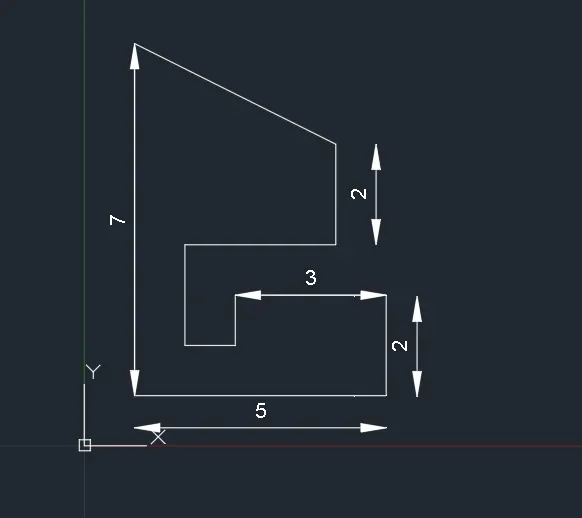
the procedure of creating p10 geometry using rectangle coordinate system:-
- take a line command by entering L in the command bar
- firstly outer rectangle is generated
- give the start point as 1,1
- specify the next point as 1,7
- specify the next point as 6,7
- specify the next point as 6,4
- specify the next point as 3,4
- specify the next point as 3,1
- then close and press enter to leave the command
- then to draw the inner rectangle 1 take line command take the start point as 3,2
- specify the next point as 2,5
- specify the next point as 2,7
- then specify the next point as 5,7
- specify the next point as 5,5
- then close and press enter to leave the command
- then the required diagram is generated
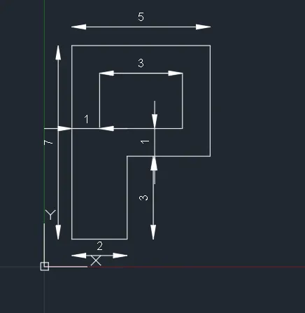
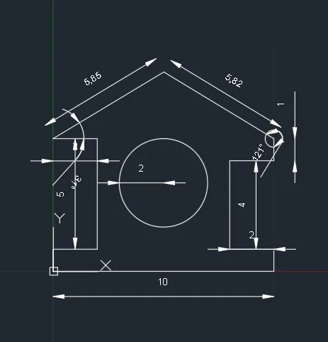
the procedure of creating wood profile geometry using the polar coordinate system:-
- take a line command by entering L in the command bar
- take start point as 0,0
- then specify the next point as @10<0
- specify the next point as @1<90
- specify the next point as @2<180
- specify the next point as @4<90
- specify the next point as @2<0
- specify the next point as @1<90
- specify the next point as @5.851<121
- specify the next point as @5.85<211
- specify the next point as @2<0
- specify the next point as @5<270
- specify the next point as @2<180
- specify the next point as @1<270
- then the required image has been created
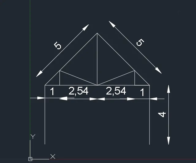
the procedure of creating queen post truss geometry using the polar coordinate system:-
- take a line command by entering L in the command bar
- take start point as 1,1
- specify the next point as @4<90
- @5<45
- @5<315
- @4<270
- then by the direct line method draw a horizontal line joining two vertical posts
- draw a vertical line from the center of the line post
- then draw a line of 1unit taking the start point as 2,5
- then by the direct line method draw the other line
- now the required picture has been created
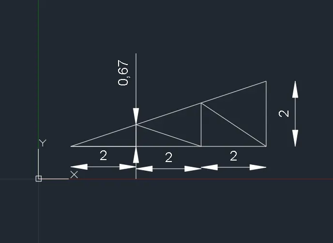
the procedure of creating mono-pitch geometry using the rectangle coordinate system:-
- take a line command by entering L in the command bar
- take a start point as 1,1
- draw a horizontal line of 6 units by direct method from 1,1
- then take line command
- specify the first as 3,1
- specify the next point as 3,1.667
- specify the next point as 5,1
- specify the next point as 5,2.553
- specify the next point as 7,1
- specify the next point as 7,3
- then enter c and leave the command
- the required image has been created