Week 3 Challenge
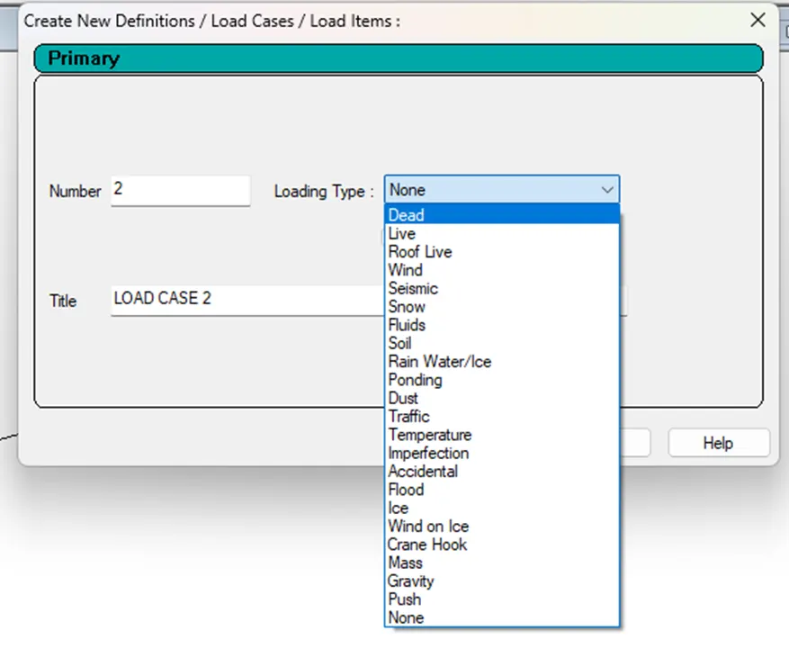
1.1 State the primary load cases to be considered for design.
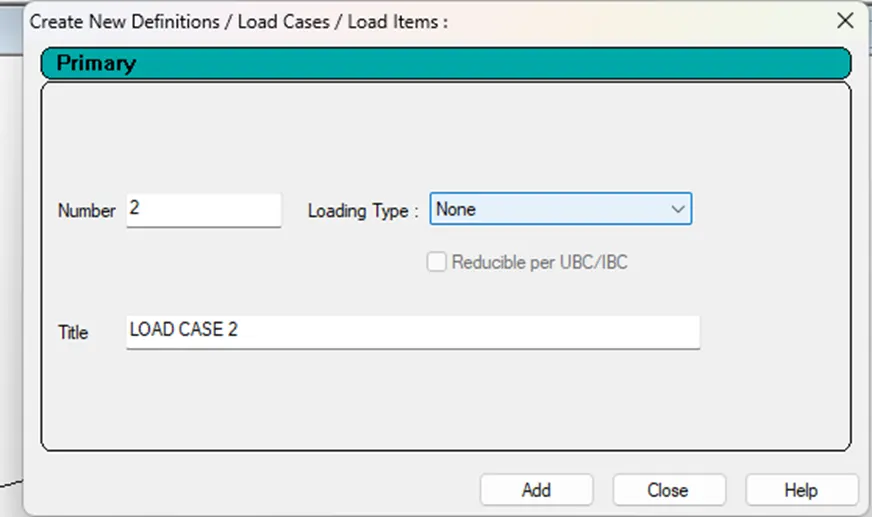
Primary load is the base for loading in STAAD Pro. Each Primary load should have a number, and a title.
If you left Title empty, STAAD Pro will accept that, but later on, it will be very difficult, to remember what is the load.
Primary load contains inside it all the individual loads which may act on Nodes, Beams, Plates.
One of the pre-defined loads, which can be included in a Primary load is Self weight.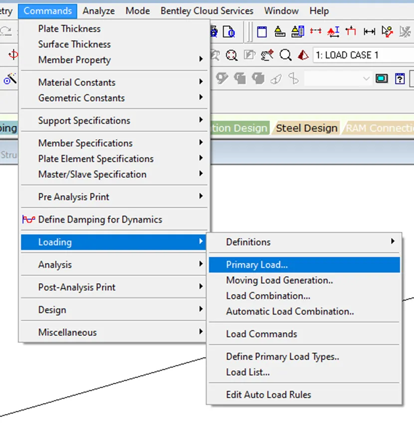
1.2 What is One-way slab?
The one-way slab can be defined as the type of slab in which the ratio of the longer to the shorter span is more than two.
Mathematically, Longer Span/Shorter Span > 2
The shorter span of the one-way slab is provided with the primary reinforcement, while the longer span is provided with the distribution reinforcement.
Examples of one-way slab are the cantilever slabs, chajjas, verandahs etc.
1.3 What is the value of unit weight of structural steel and soil?
Unit weight is also called specific weight, is a measure of the weight or mass of a substance per unit volume.
Unit weight of structural steel is 78.5 kN/m3 and Soil is 18.0 kN/m3.
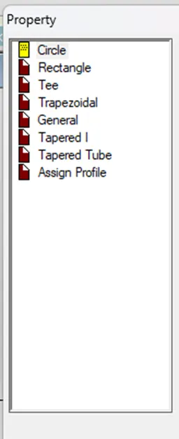
1.4 Name few sections that can be defined using Properties tab in STAAD Pro
Sections that can be defined using Properties tab in STAAD Pro are Circle, Rectangle, Tee, Trapezoidal, General, Tapered I, and Tapered Tube.
1.5 DEFINE Primary Beams.
Primary Beams: The beams that are connecting columns for transferring loads of a structure directly to the columns are known as primary beams. Usually, primary beams are simply supported and they are provided in a regular building structure. The depth of primary beams is always greater than secondary beams. Primary beams acts as a medium between columns and secondary beams.
2.1 State the factors and parameters that influence the design pressure intensity of a high-rise building.
Wind load has to be considered when designing high-rise buildings. Up to 10 stories the wind load rarely affects the design, for taller buildings the effect is more crucial.
The wind pressure at any height above mean ground level shall be obtained by the following relationship between wind pressure and wind speed.
pz = 0.6 Vz2
where pz = wind pressure in N/mm2 at height z, and Vz= design wind speed in m/s at height z.
Design wind speed Vz = Vb k1 k2 k3 k4
where Vb is the basic wind speed, k1 is the probability factor or risk coefficient, k2 is the height and terrain multiplier, k3 is the topography factor, and k4 is the importance factor for cyclonic region.
2.2 Mention the load transfer process of a Reinforced Concrete Building.
Generally, there are two types of load paths (process), they are Gravity load path and lateral load path.
Gravity load path: In this process the vertical gravity load (includes the dead load of the structure and live load on the structure) acts on the slab are transferred efficiently to the secondary beams and then to the primary beams. It is then transferred to columns and from columns to the supports, and finally from supports to the earth.
Lateral load path: In this process, lateral loads which are earthquake loads and wind loads are transferred efficiently through the building. The components of the lateral load path are Horizontal components (Roof, Floor and Foundation) and vertical components (Shear wall).
3.1 Differentiate One-Way and Two way slabs. Elaborate each slab type.
|
One way slab |
Two way slab |
|
In one way slab, the ratio of longer span to shorter span is equal to or greater than 2. |
In two way slab, the ratio of longer span to shorter span is less than 2. |
|
Slab panel is supported on two opposite sides in short direction of one-way slab. |
Slab panel is supported on four sides of two-way slab. |
|
One way slab bends or deflect in a direction perpendicular to the supporting edges. |
Two way slab bend or deflect in both directions. |
|
Main reinforcement is provided in only one direction for one way slabs. |
Main reinforcement is provided in both the direction for two way slabs. |
|
The main source of load transmission is the longer direction. |
The shorter and longer sides are the main source for transmission of load. |
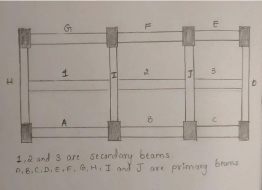
3.2 Explain the concept of secondary beams with proper sketch.
Secondary beam: The beams that are connecting primary beams for transferring loads of a structure to the primary beams and not directly to the columns are known as secondary beams. These beams are provided for supporting and reducing the deflection of beams and slabs.
3.3 Mention the Primary load cases.
a. State the Indian Standards for each load case.
b. Detail the parameters of each load case.
c. Brief each load case.
a. The IS stands for the Indian Standard Code, which is a series of standards established by the Bureau of Indian Standards (BIS) to ensure the quality and safety of products and services in India.
Indian standards for each load case:
- Dead load – IS 875 (Part-1):1987
- Live or imposed load - IS 875 (Part-2):1987
- Wind load – IS 875 (Part-3):1987
- Snow load – IS 875 (Part-4):1987
- Special loads and load combinations – IS 875 (Part-5):1987
- Seismic load – IS 1893 (Part I),2002
b. Parameters of each load case
Dead load – Volume and unit weight (By calculating the volume of each member and multiplying it by the unit weight of the materials from which it is composed).
Live load – These loads are produced by the intended use or occupancy of the building including weights of movable partitions or furniture. (Load value, load eccentricity and loading direction)
Wind load – Height of structure, wind speed, wind direction, exposure and coefficients are the parameters of wind load.
Seismic load – Seismic loading depends primarily on seismic hazard, geotechnical parameters of the site, and structure’s natural frequency.
c. Load cases are sets of loads that act on the structure, such as dead load, live load, wind load, earthquake load, etc.
Dead Load (DL) – Consists of weight of the structural elements.
Live Load (LL) – All the movable objects produce an imposed load on the structure.
Wind Load (WL) – It is the pressure caused by the wind that is delivered to a structure.
Seismic/Earthquake load – The force or shaking that a structure experiences during an earthquake.
4. Detail the steps involved in assigning Properties and Support to a model using STAAD Pro sequentially.
· Define units and coordinate system:
Defining units and coordinate system in STAAD Pro ensure that the dimensions, loads, and results are consistent and accurate.
· Choose the section properties and materials:
Choose the section properties and materials for the beams and columns. STAAD has built in library of standard sections and materials that we can use or modify as needed. By using member property and member material command assign the properties to the element.
· Assign supports and releases:
Assign the supports and releases that will constrain the movement and rotation of element. STAAD Pro offers various types of supports, such as fixed, pinned, roller, spring, and elastic. By using supports command assign supports to the beams and columns, use release command to specify the degrees of freedom.
5. Brief the steps to be followed to create and assign secondary beams in STAAD Pro
Open STAAD Pro software by double clicking on the icon.
Create new project. Define units.
Choose add beams. Go to Geometry tab and select run structure wizard.
Choose frame model and select bay frame.
Input length, height, width and number of bays. Click on apply.
Now, transfer the model.
Select the primary beam and go to geometry tab, choose insert node command.
Insert nodes into beam dialog box appears.
To add new point, input the distance value in new insertion point or add mid point or add n points and click on OK.
Similarly create nodes in other primary beams.
Now, go to geometry tab and choose add beam command and then add beam from point to point option.
Create beam by clicking on the nodes.
The beams created are secondary beams.
Practical
1. Calculate the wind pressure for the given building
a. Building Dimension: 20m x 30m x 20m height RCC
b. Building usage: Hospital block in city centre
c. Location: Darjeeling
2. Calculate the Dead load and Live load for the above building with reference to IS standards (assume suitable sections)
1. Calculation of Wind Pressure:
The wind pressure intensities are calculated as per IS: 875 (Part-3) using the formula, (clause 5.4, IS:875 (Part-3)-1987)
PZ = 0.6 x Vz2
Where, Pz – Design wind pressure
VZ – Design wind speed
The design wind speed for any geographic location is calculated using the formula, (clause 5.3, IS:875 (Part-3)-1987)
Vz = Vb x K1 x K2 x K3
Where, Vb – Basic wind speed (Appendix-A, IS:875 (Part-3)-1987)
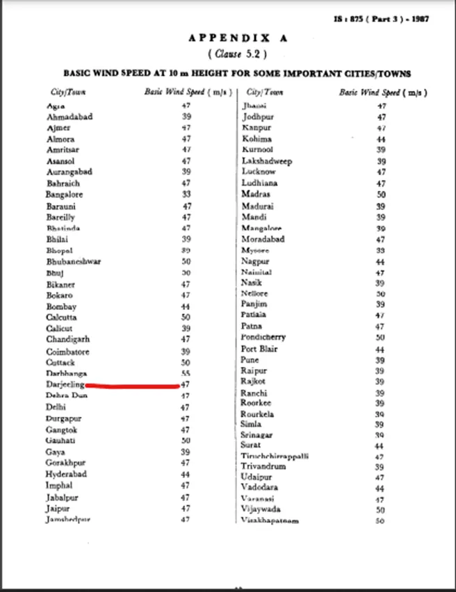
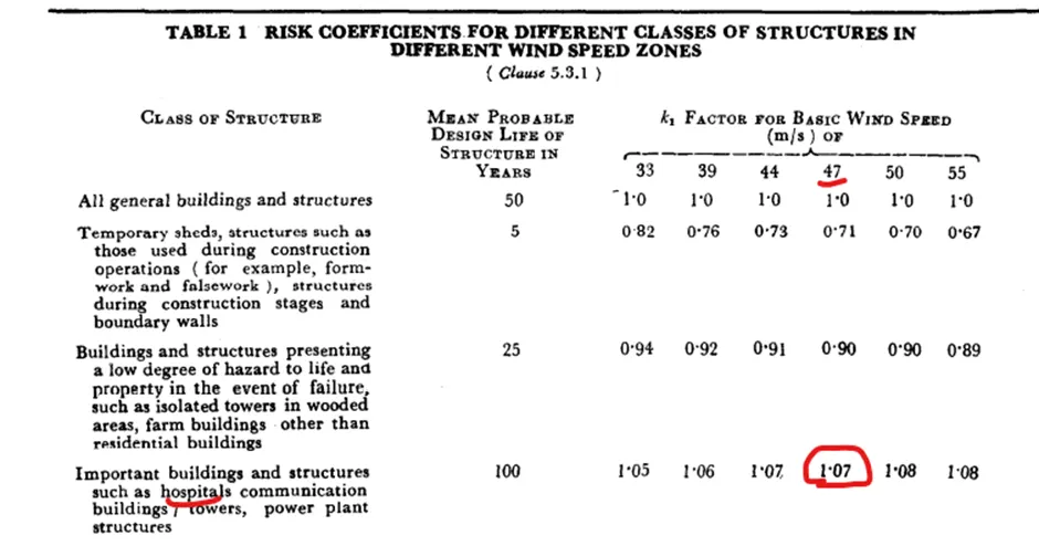
K1 – Risk coefficient factor (Table-1, IS:875 (Part-3)-1987)
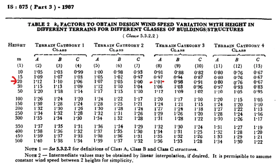
K2 – Terrain & height factor (Table-2, IS:875 (Part-3)-1987)
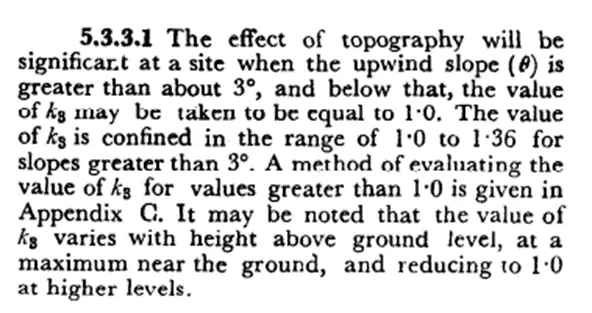
K3 – Topography factor (Clause 5.3.3.1, IS:875 (Part-3)-1987)
For the given location i.e., Darjeeling, Basic wind speed (Vb) = 47 m/s
Risk Coefficient factor (K1) = 1.07 (As the structure is hospital building, from table 1)
Terrain & height factor (K2) = 1.01
Topography factor (K3) = 1.0
Vz = Vb x K1 x K2 x K3
Vz = 47 x 1.07 x 1.01 x 1.0
Vz = 50.79 m/s
Now, Pz = 0.6 x Vz2
Pz = 0.6 x (50.79)2
Pz = 1547.77 N/m2
Pz = 1.54 kN/m2
1. Calculation of Dead load and Live load with reference to IS standards:
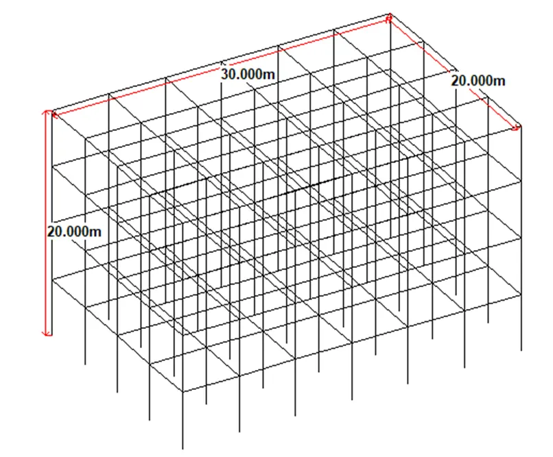
The following are the specifications assumed for the building:
Beam dimensions – 0.4mx0.25m
Column dimensions – 0.5mx0.4m
Slab thickness – 0.12m
Height of each floor – 5m
Dead load calculation:
As per IS 875 (Part 1)-1987 code standards the dead loads are calculated.
Self weight of slab = Thickness of the slab x Unit weight of RCC
= 0.12 x 25 (Unit weight of RCC is 25Kn/m3)
= 3 kN/m2
Self weight of Beam = Cross section of the beam x Unit weight of RCC
= 0.4 x 0.25 x 25
= 2.5 kN/m2
Self weight of column = Volume of column x Unit weight of RCC
= 0.5 x 0.4 x 25
= 5 kN/m2
Floor finishers = 50mm thickness (Mortar unit weight=20 kN/m3)
= 0.05 x 20
= 1 kN/m2
External wall load = Thickness of external wall x Unit weight of Brick x height of each floor
(assumed thickness of external wall is 0.23m, unit weight of brick is 19 kN/m3)
= 0.23 x 19 x 5
= 21.85 kN/m
Internal wall load = Thickness of internal wall x Unit weight of Brick x height of each floor
(assumed thickness of external wall is 0.125m)
= 0.125 x 20 x 5
= 12.5kN/m
Total wall load = 21.85 + 12.5 = 34.35 kN/m
Live load calculation:
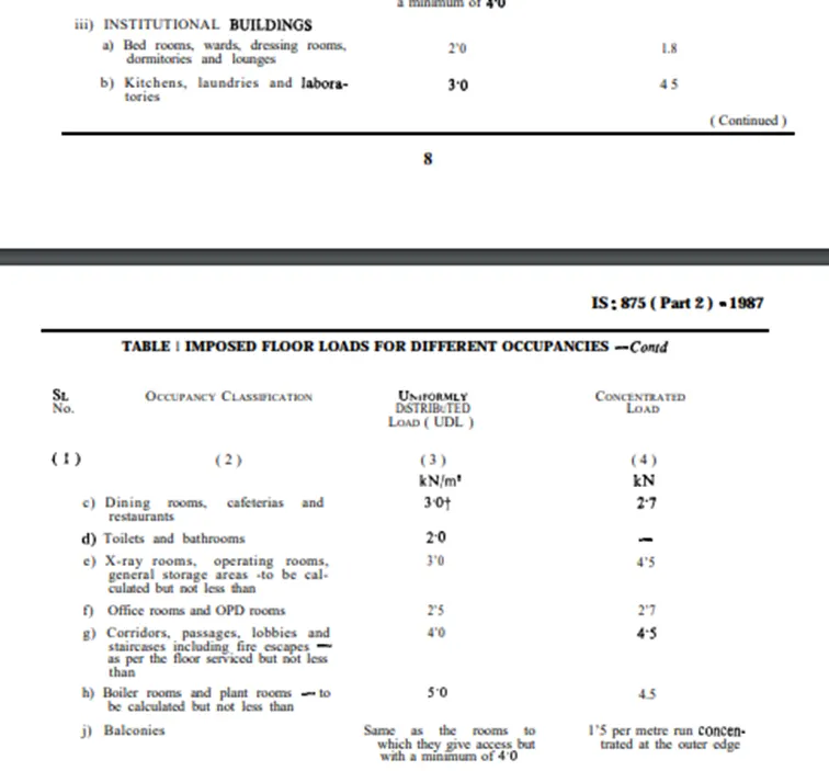
Live loads are different for different buildings and structures. It keeps changing from time to time even on same structure. The minimum live loads per square meter area for different types of structures are given in IS 875(Part 2)-1987.
As hospital building is classified under Group C Category, live loads for institutional building are considered.