Creating Architectural and Structural model with 3D rendering using REVIT
1. Answer:
Aim: To select the type of structure among Multi-Unit Residential Apartment, Office Building and School Building for construction.
Introduction:
Multi-Unit Residential Apartment: An apartment is a block of flats, contains multiple housing units for residential inhabitants. Housing units can be next to each other or stacked one over the other in multiple floors. Apartment buildings can range in many sizes. The inhabitants share the common amenities in the unit such as parking area, stairway, lift, garden, swimming pool etc.
Office Building: An office building will often be divided into sections, or floors, for different organisations, or the whole building can be used by one organisation. In an office different people perform many different roles and tasks within an organisation and may have differing requirements in the workplace. For the smooth working environment, the building should have reception, office spaces, enclosed cubicles, private meeting facilities, conference areas, storage space, cafeteria, break area and welfare facilities. The primary purpose of an office building is to provide a healthy, safe, and efficient working environment for its users.
School Building: School building is a place for education activities and comes under Group B-educational buildings. A school building contains classrooms, library, staff-room, head teacher’s room, laboratory, computer room, playground, toilets, assembly hall etc. School buildings must be designed in such a way that will provide equal access to all. Building provides safety and security to its occupants by providing fire protection system in it.
Procedure:
For this project a Multi-Unit Residential Apartment has selected for Construction.
- The apartment building consisting of four stories above a parking slot.
- The four floors contain three flats each and providing accessibility through both staircase and lift.
- The apartment unit is made of masonry construction.
- The apartment building follows the NBC requirements.
- The architectural plan including doors, windows, furniture required for residential building, lighting and structural plan including foundation, columns, beams, walls is prepared in this project.
Result:
For this project, a Multi-Unit Residential Apartment is selected for design and construction.
2. Answer:
Aim: To assume the reasonable assumptions for geographic and location details for the project and identifying the modelling requirements for this project from NBC.
Introduction:
To define the location of the project in the real world and to get the realistic view for the project by creating real shadows, views based on the natural light availability the Geographic Location is required.
National Building Code (NBC) general requirements for residential apartments are Zoning and land use regulations, Building setbacks and Height Restrictions, Safety and security measures, Fire protection and emergency exits Environmental sustainability guidelines
While designing a residential project one must consider and follow the NBC guidelines to create a safe structure.
Procedure:
Open the Revit software.
Open a new construction project.
To add location details, go to Manage tab.

Choose location option from the Project location panel.
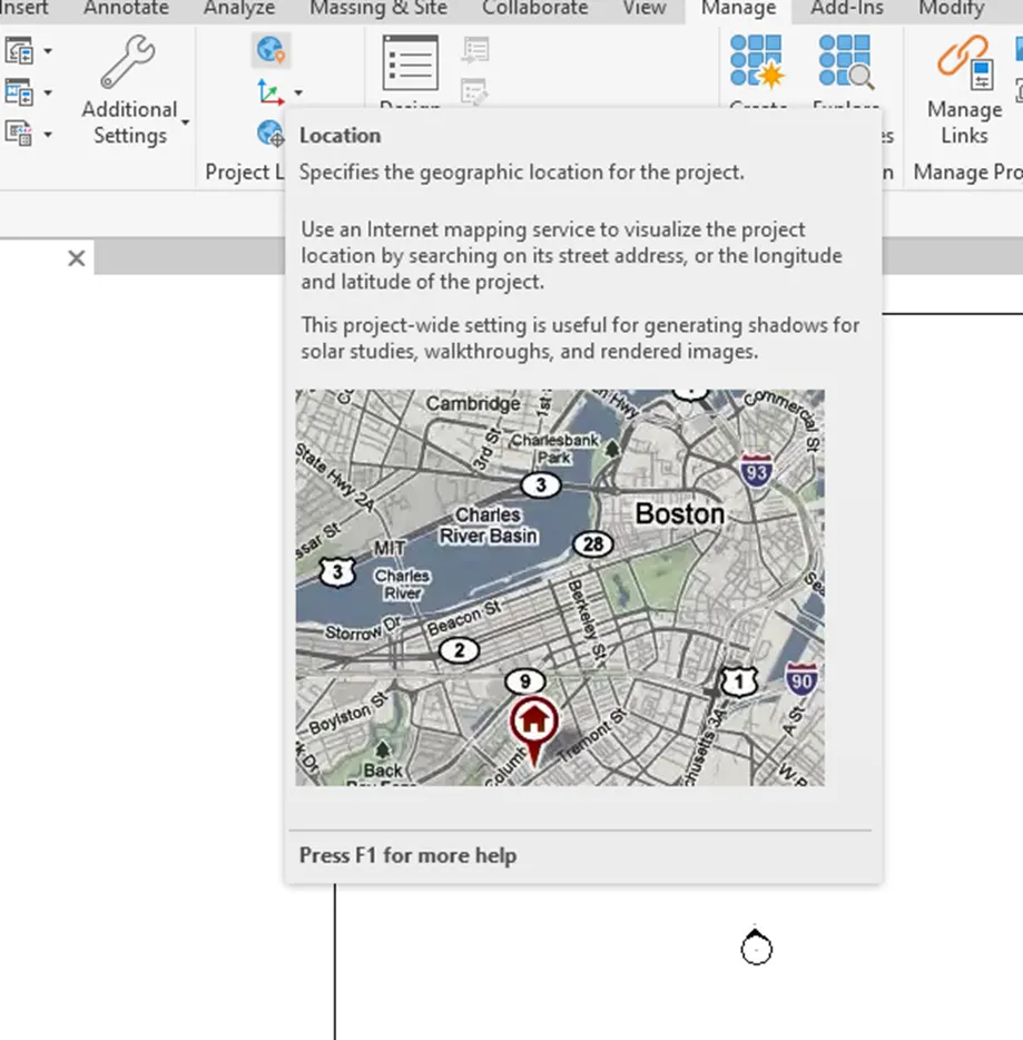
The Location and Site dialog box appears:
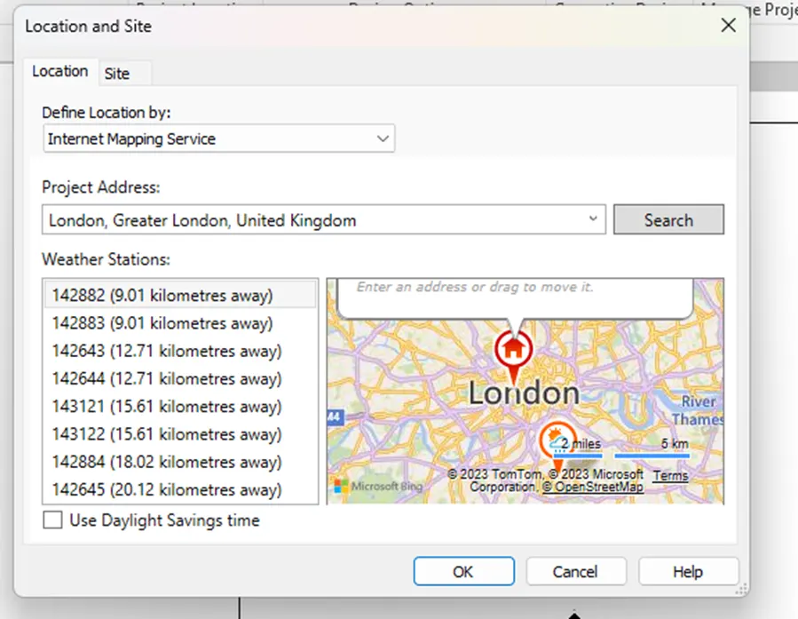
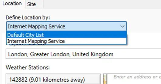
Select Define location by Default City List.
Choose the city, latitude and longitude from the list and then click on OK.
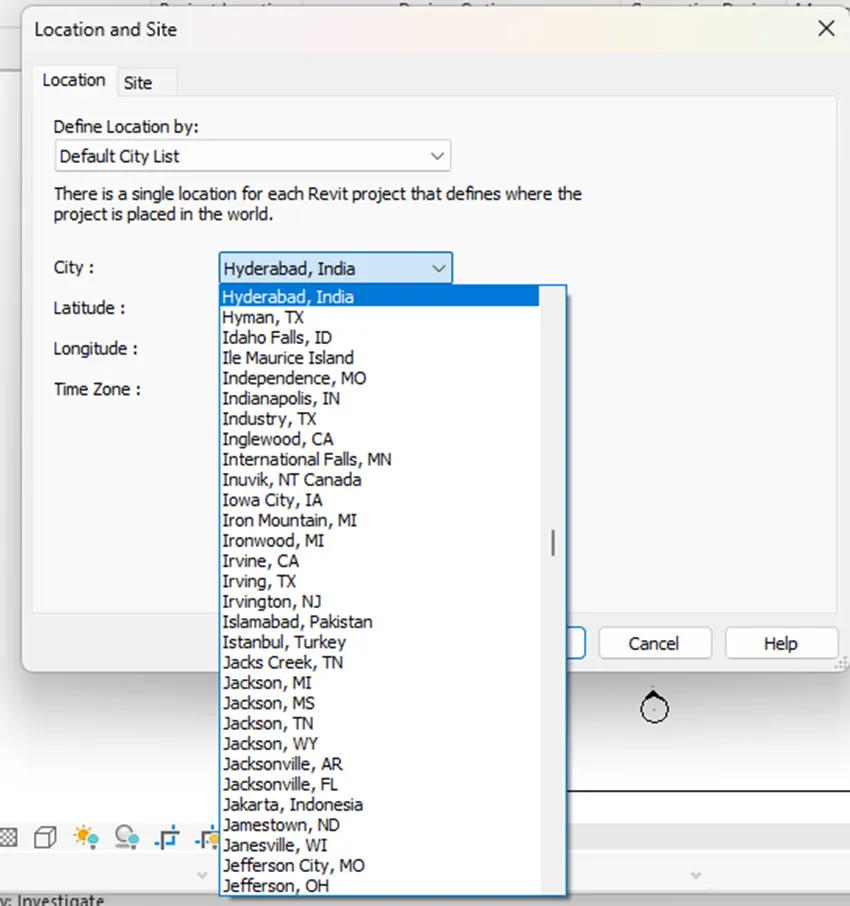
The geographical location has been selected.
Now save the file.
Identifying the NBC Requirements:
The NBC categorises land into different zones, such as residential, commercial, industrial, recreational, and mixed use zones, each with specific guidelines regarding permissible activities, building height limits, parking requirements, setbacks etc.
Hence the project is on a residential apartment, according to NBC the building is categorized under Residential buildings.
Setbacks typically refer to the minimum distance between the building and its boundaries or adjacent structures. This ensures proper ventilation and natural lighting.
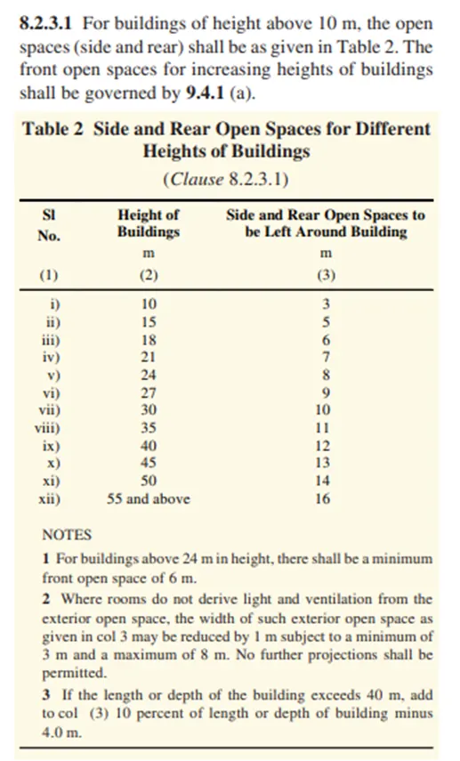
The height of the building in this project is approximately 17 m, hence the setback (open space) provided on the sides should not be less than be 5 m.
The type of building is type1, the Floor Area Ratio is Unlimited for residential building.
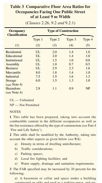
The plot size for this project is 20 m X 30 m (600 m2) and individual floor area is 211.14 m2 floor area ratio is 1.75.
Result:
The geographic location for the project is selected using Manage tab and modelling requirements are identified from the National Building Code.
<!-- [if !supportLists]-->1. 3. Answer:
Aim: To include the components like foundation, columns, beams, roof, floor, stairs and elevator or shaft opening to the selected type of structure.
Procedure:
Open the Revit software.
Open the previously created project file.
Go to elevations and create levels using levels option from the Architecture tab.
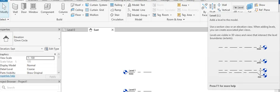
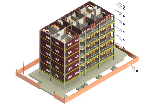
Creating levels for foundation level, ground floor, first floor, second floor, third floor, fourth floor, terrace floor and parapet level.
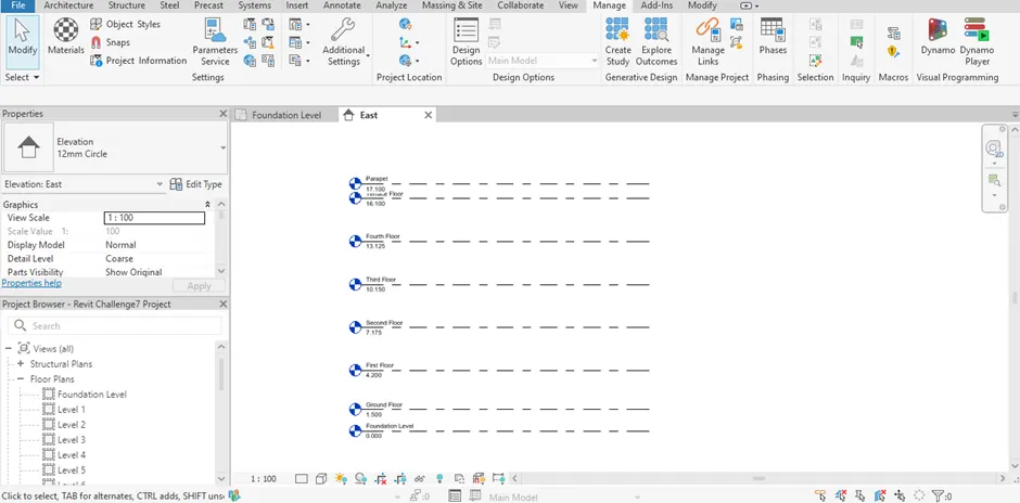
Go to floor level and create longitudinal and transverse grids by using grids option from the architecture tab.
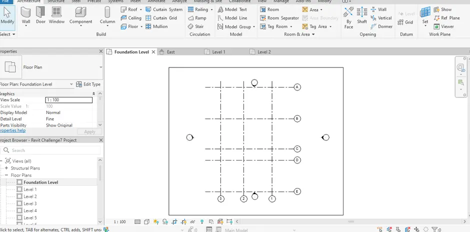
Adding foundations:
Go to structure tab and select Isolated foundation.
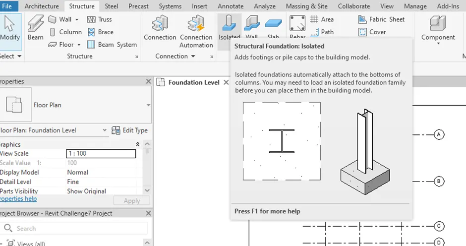
Now choose “At Grid Intersection” option.
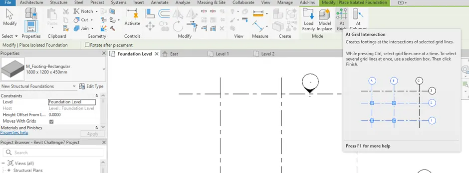
Select all the grids and click on finish option.
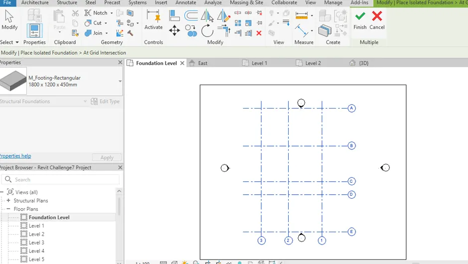
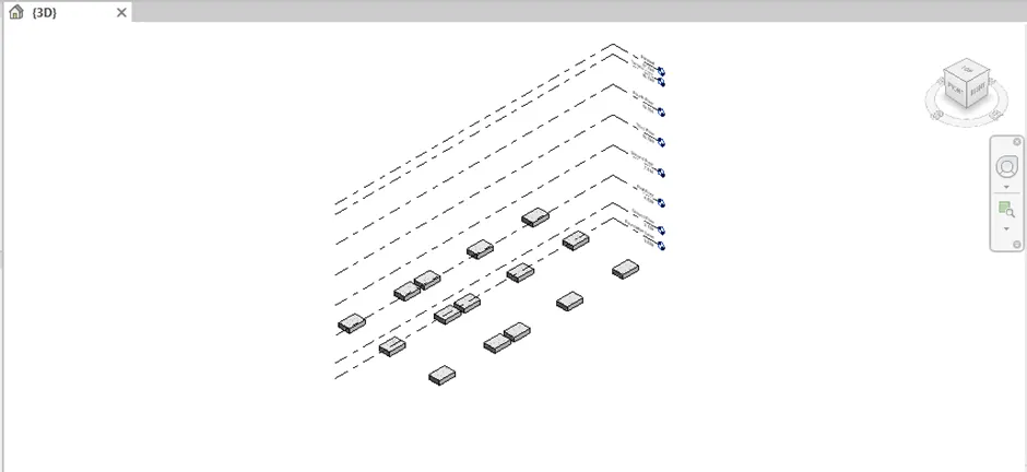
Go to 3D view and check whether the foundation is created or not.
Adding columns:
Go to structure tab and select column option.
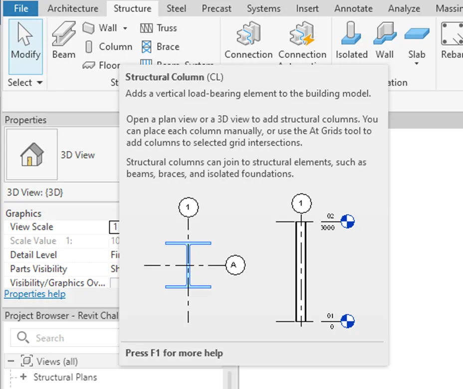
Now choose vertical column option.
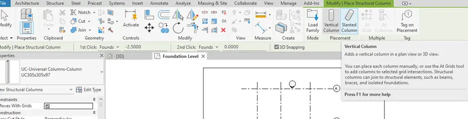
Select at grid intersection option.

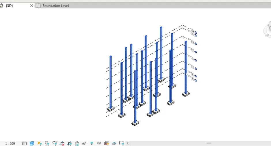
Select the grids and click on finish.
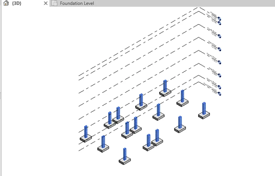
Now go to properties and select top level as terrace floor.
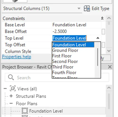
Columns are created.
 '
'
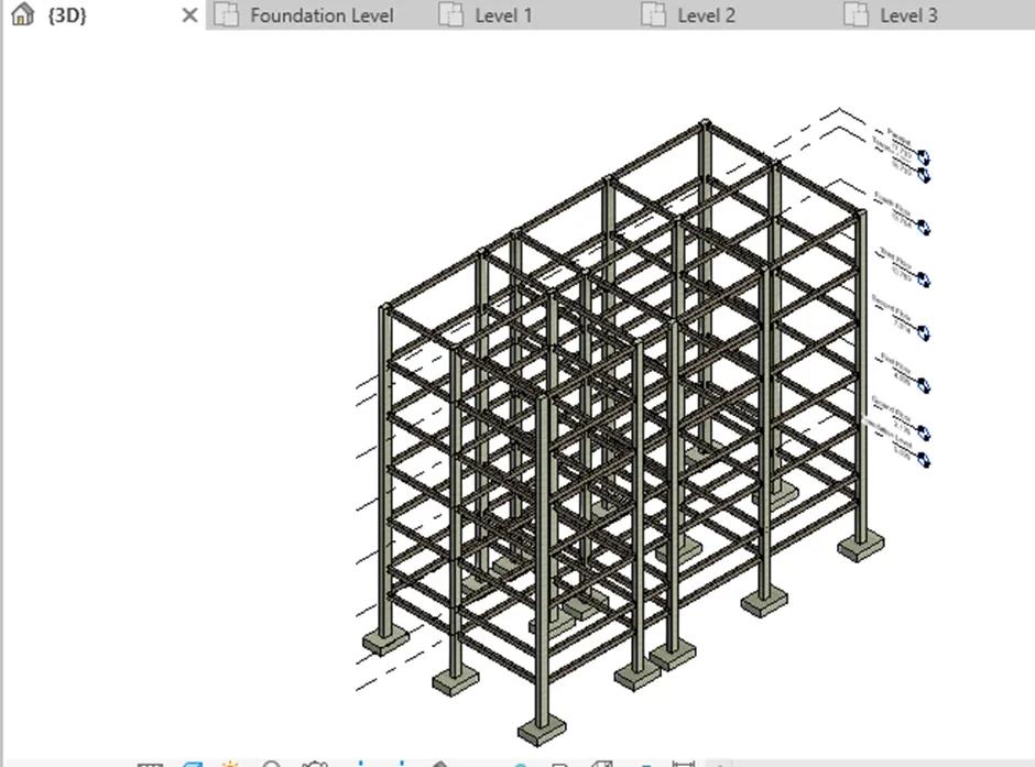
Adding Beams:
Go to structure tab and select the beam option.
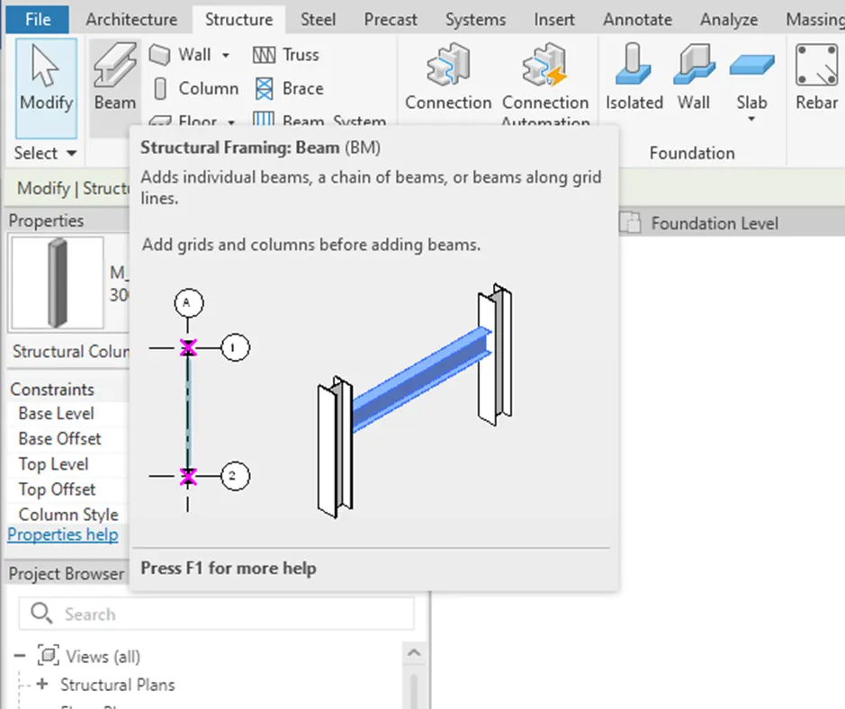
Choose the line option and connect the columns with beams.
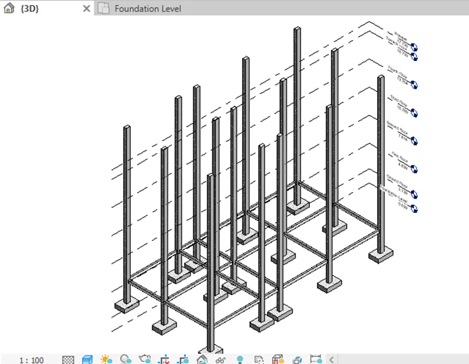
Similarly create beams in all levels.
Adding roof:
Go to Architecture tab and select Roof option.
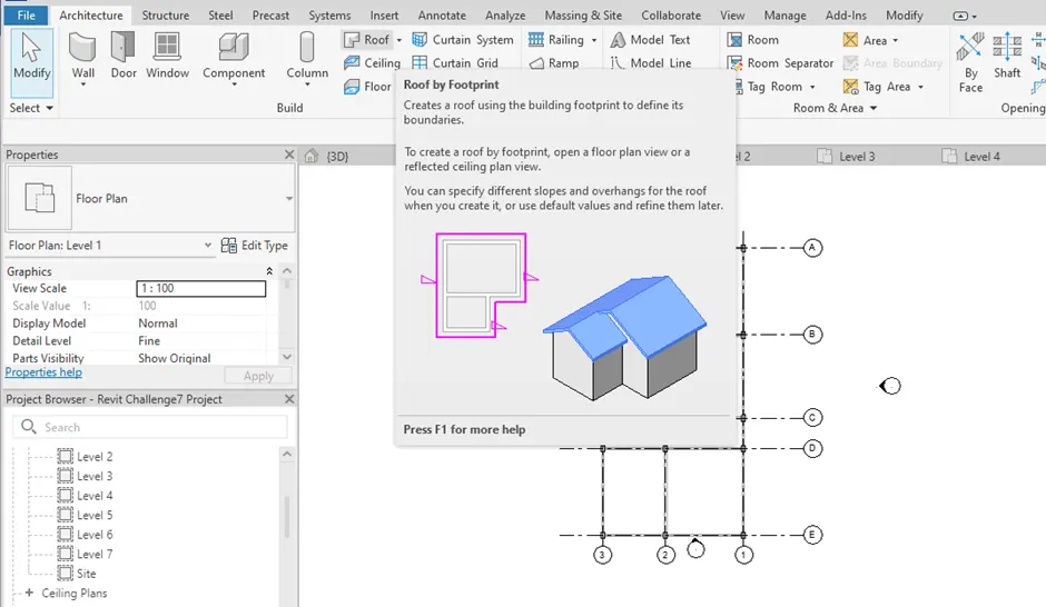
Drop down and choose Roof by footprint option.
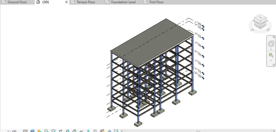
Select a flat roof from the properties browser.
Select the roof using line option and click on finish option.
Go to 3D view to view the Roof.
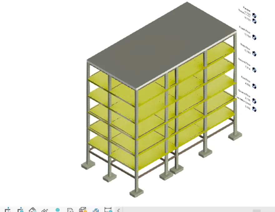
Adding slab:
Go to Structure tab and select slab option.
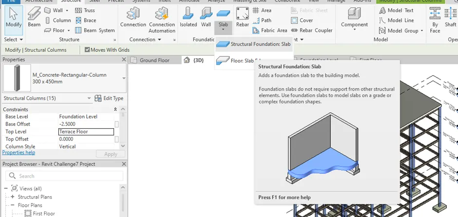
Choose line or rectangle tool and draw the slab outline.
Click on finish option.
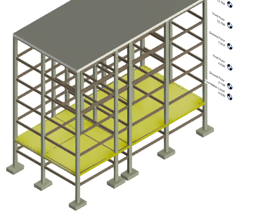
Similarly add slab to each floor.
Adding floors:
Go to Structure tab and choose floor option.
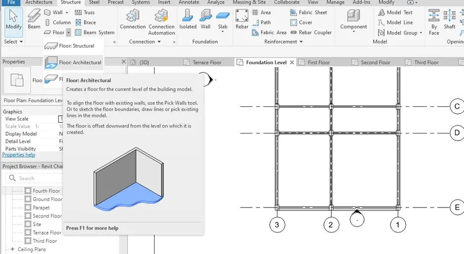
Now select the outline for floor and click on finish option.
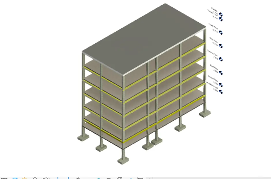
Creating floor opening for elevator and stairs:
Go to Architecture tab and select shaft option from the opening panel.
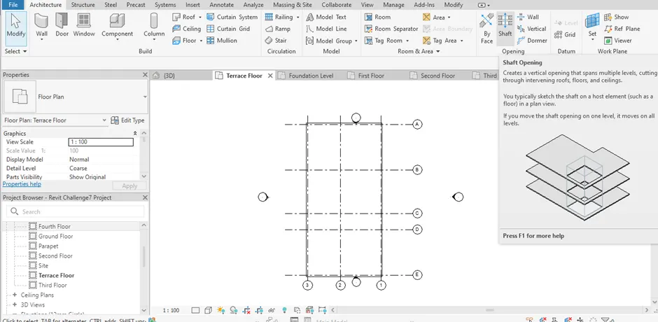
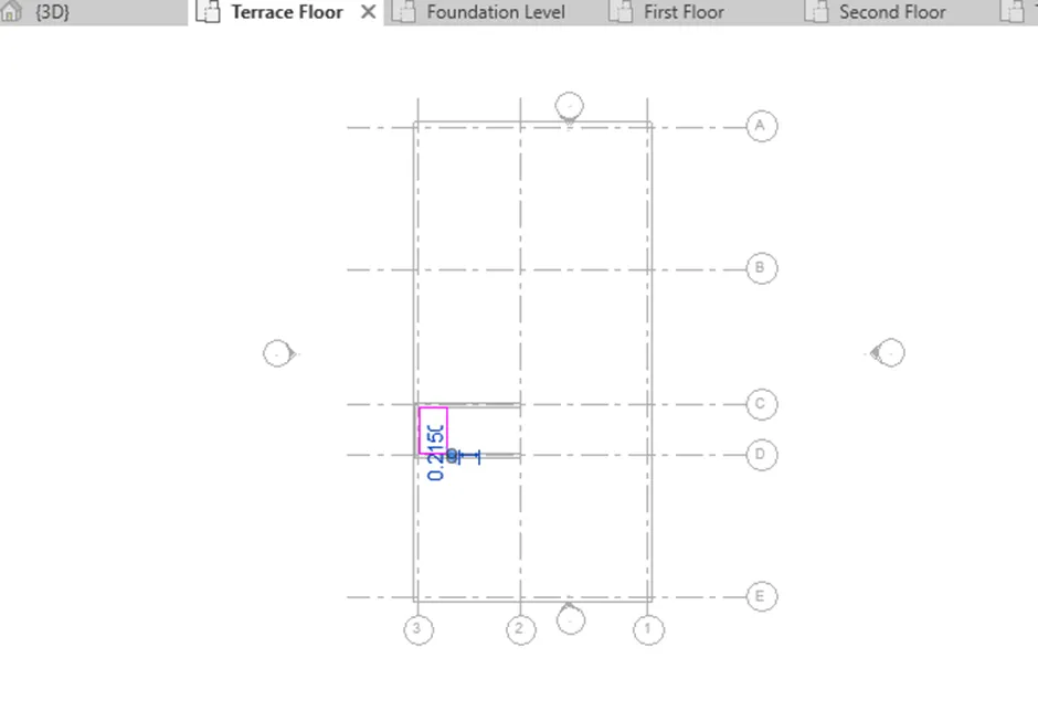
Choose line or rectangle option and create shaft opening for elevator and click on finish option.
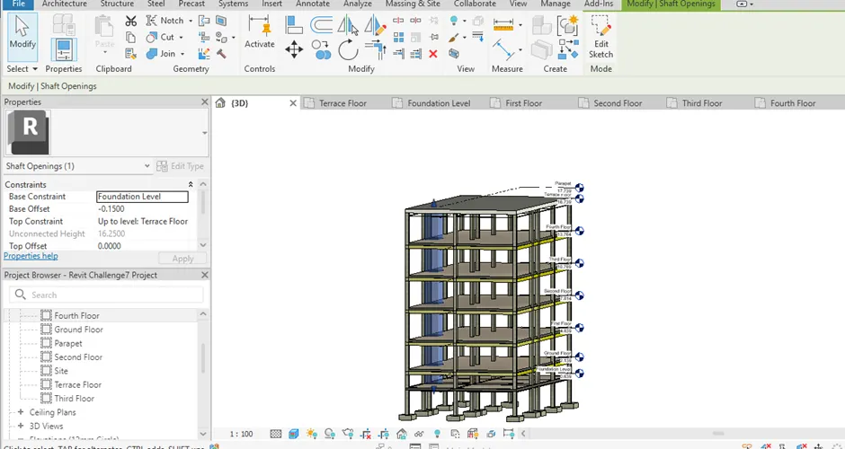
Go to 3D View to view the opening.
Similarly creating opening for stairs.
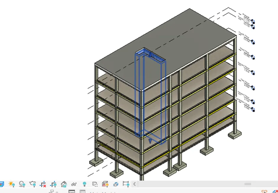
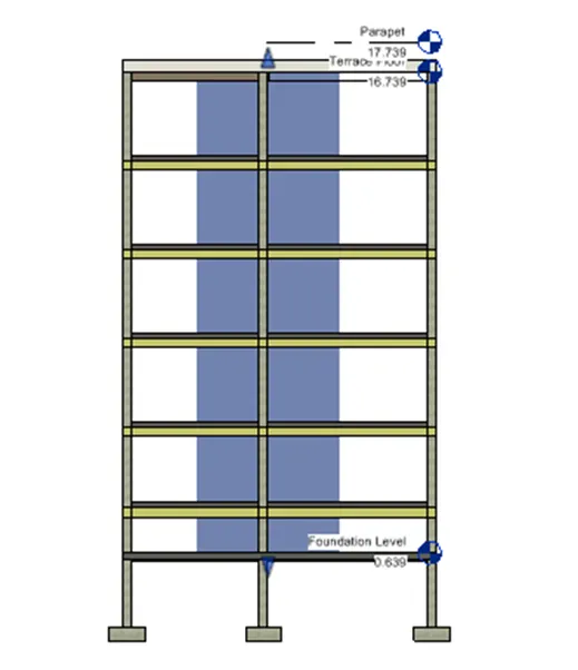
Shaft opening is created.
Result: The components like foundation, columns, beams, roof, floor, stairs and elevator or shaft opening are included to the Residential building model.
<!-- [if !supportLists]-->1. 4.Answer:
Aim: To add the components required for architecture model of the residential building.
Introduction:
Architecture model includes exterior and interior wall, furniture, stairs and elevator, exterior and interior lighting, topographic components, and ither finishing components. Revit itself provides all the architecture components through load family to make the model more efficient and realistic.
Procedure:
Open the Revit software.
Open the previously created structural model of the Residential apartment unit.
<!--[endif]-->Creating wall layout with appropriate material and finishing
Go to floor plan.
Now go to Architecture tab and select wall tool.
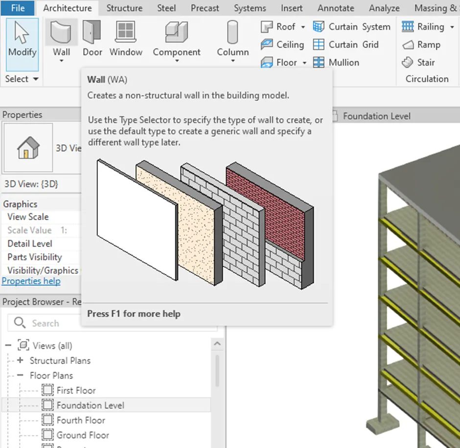
Drop down the option and select Architectural wall.
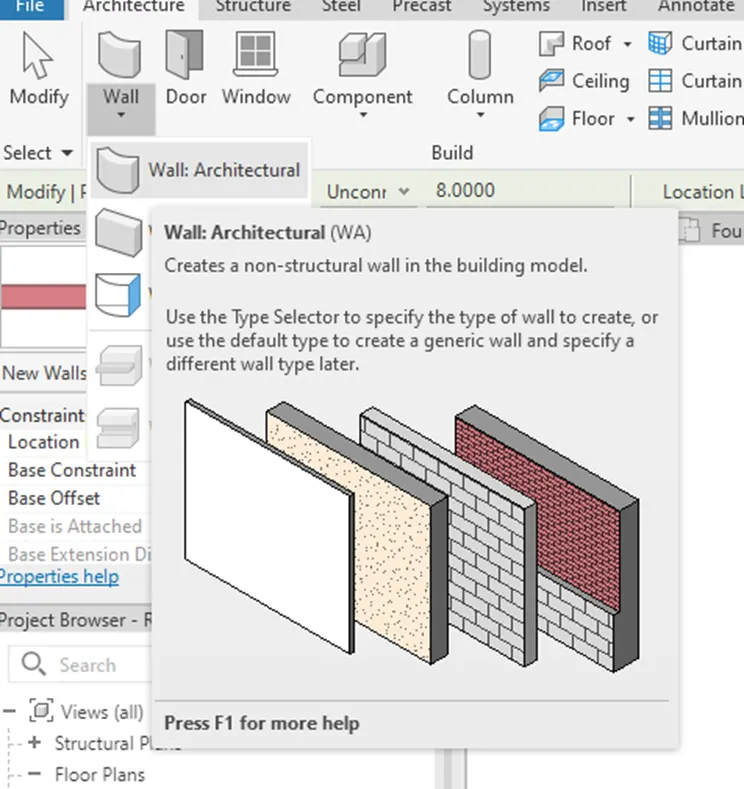
Now create exterior walls in the model.
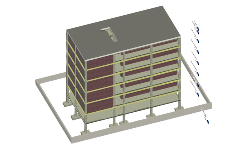
Create base floor.
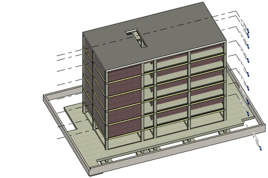
Layout:
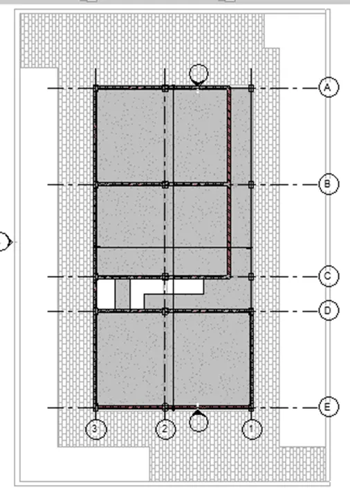
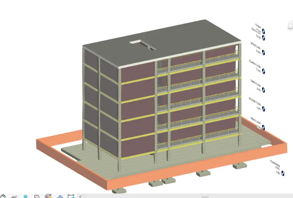
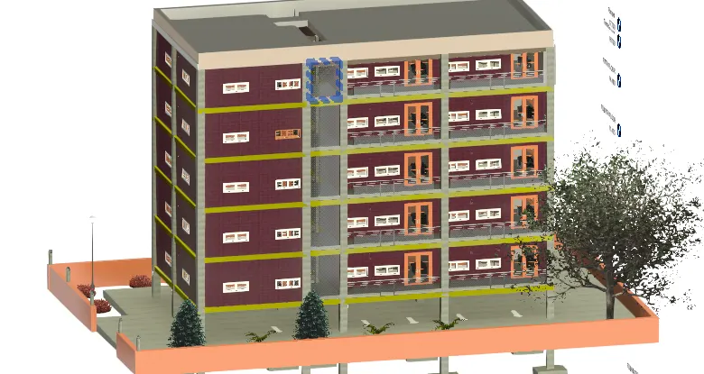
Exterior façade with fancy finish
Go to architecture tab and choose railing option.
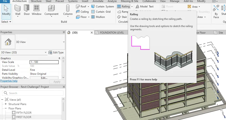
Place the railing on the edges of the floor in the corridor.
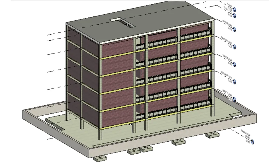
Add finishes to the external walls by assigning different materials for appearance.
<!--[endif]-->Interior partition walls to size rooms
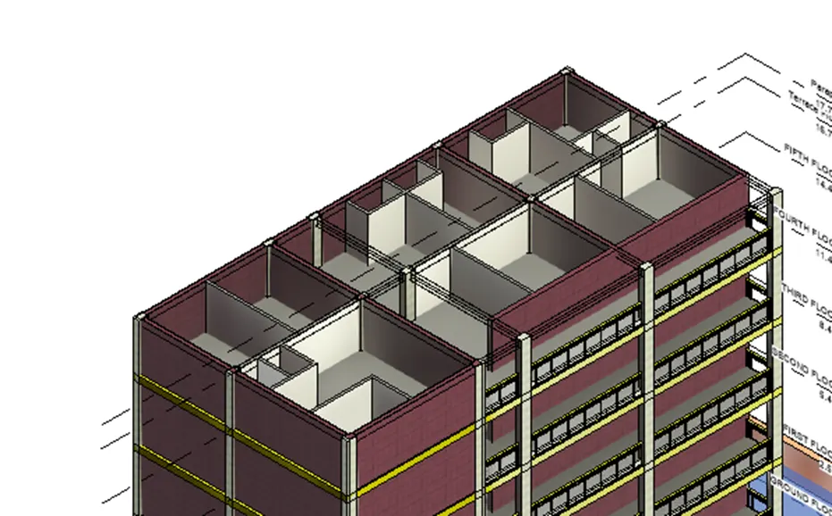
Go to Architecture tab and select wall tool.
Drop down the option and choose architectural wall and interior wall type and create the walls in the floor plan.
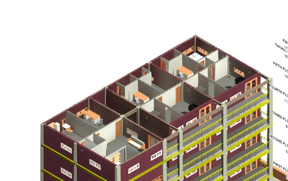
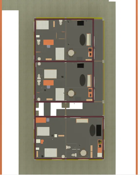
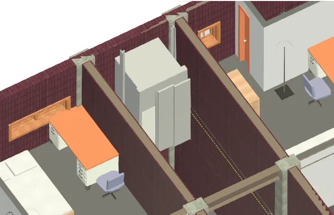
Components to add details to a room (Desk, Chair, Lighting, Plumbing fixtures)
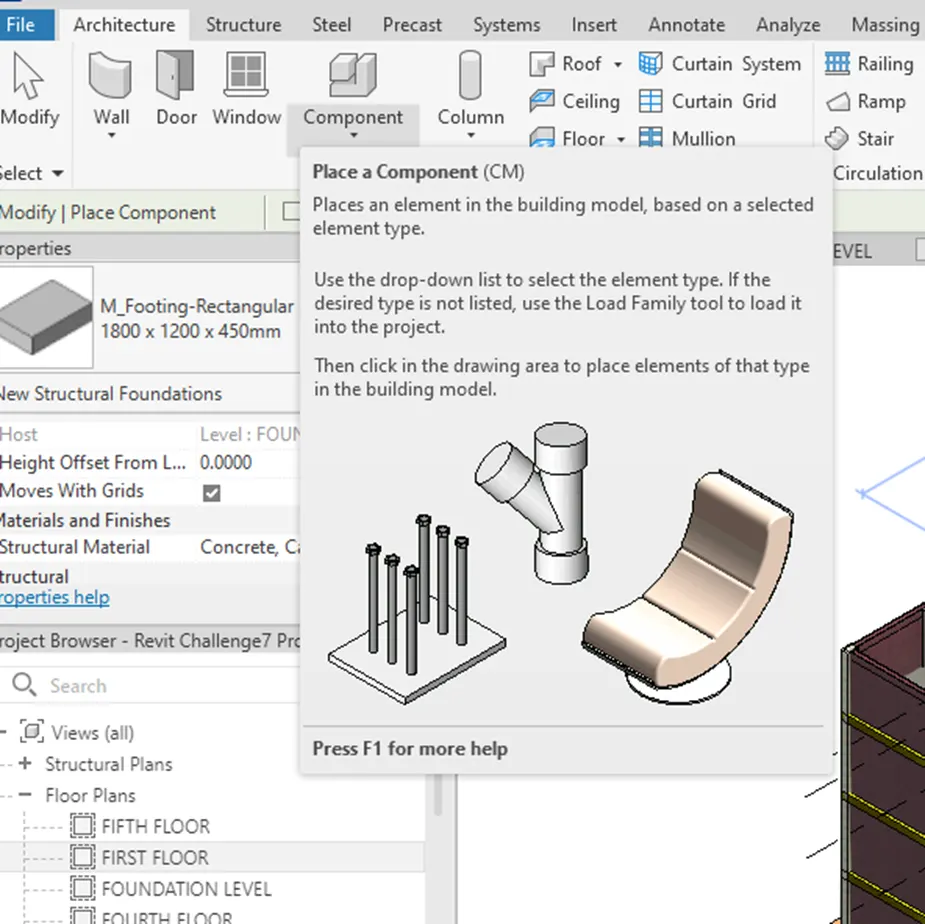
Go to Architecture tab and select component option.
Choose load family option.
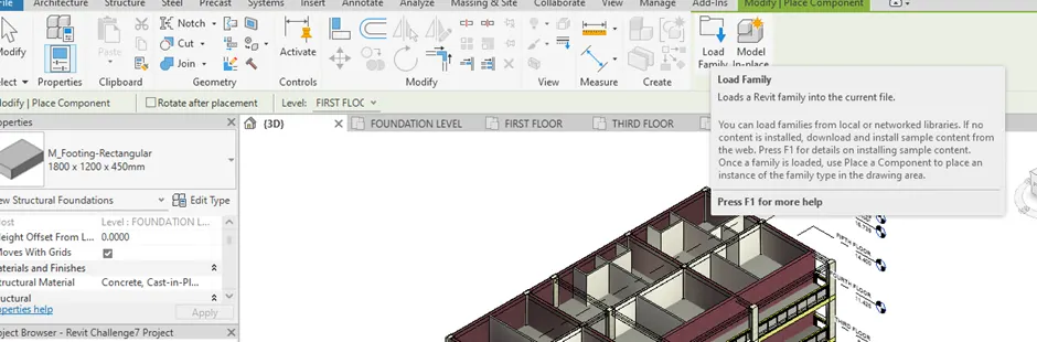
Select the components from the different categories in the load family.
Place the components in the model.
Adding components such as stairs and elevators
Go to ground floor plan.
Go to Architecture tab and choose stair option from the circulation panel.
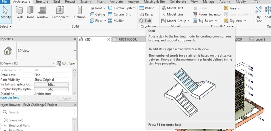
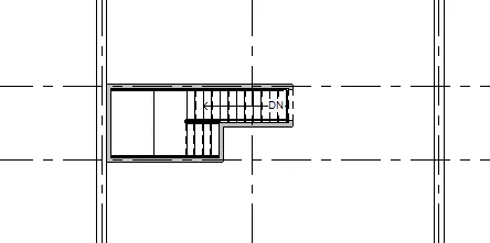
Now create staircase using the tools in the components panel.

Click on run otion and create risers.
Then, click on landing option and connect the two runs.
Connect the staircase to all the floor levels using properties browser.
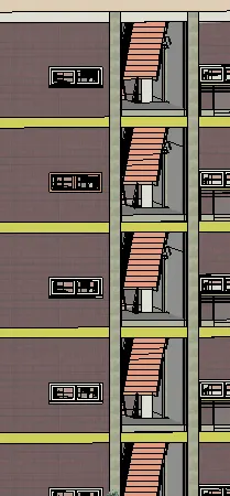
Go to architecture tab and choose component option.
Go to load family and choose speciality equipment category.
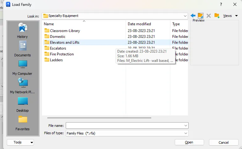
Now select the elevators family and then choose an element from the list.
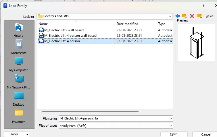
Now place the element in the model.
One wall on the side of the building with glass panels
Go to floor plan.
Go to architecture tab and choose wall option.
Select the glazed wall and place it in the model.
Including interior and exterior lighting fixtures
Go to architecture tab and choose component option.
Go to load family and selcet lighting category.
Now choose architectural family and then choose internal option.
Select the element from the list and place it in the model.
Now choose external lighting option.
Select the element and place it in the model.
Placing topographic components from outside
Go to architecture tab and choose component option.
Go to load family and selcet planting category.
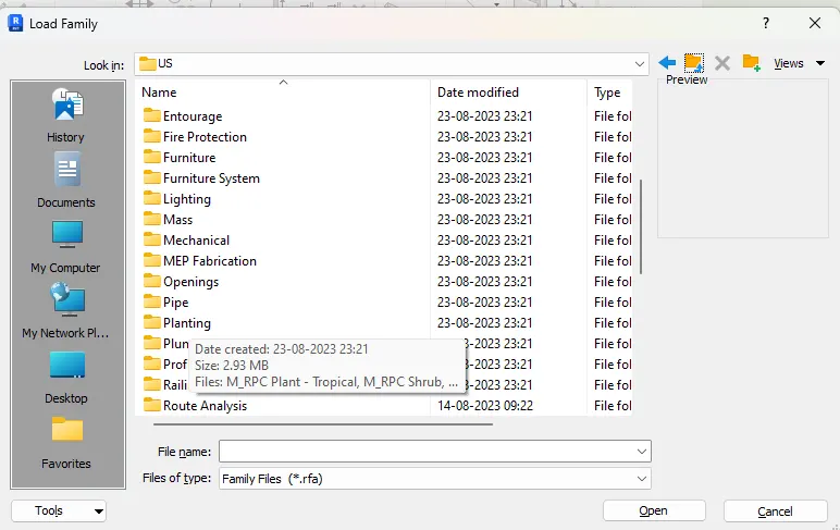
Select the elements from the list.
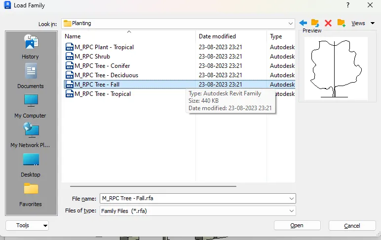
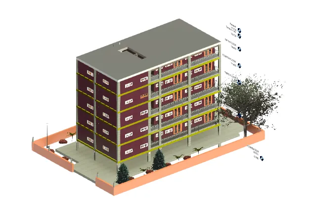
Place the element in the model.
Go to site option in load family.
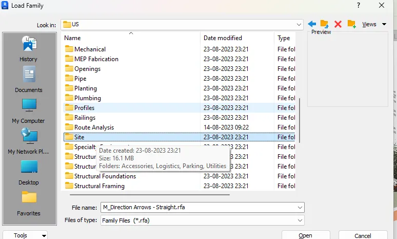
Now choose parking category and then selct the element.
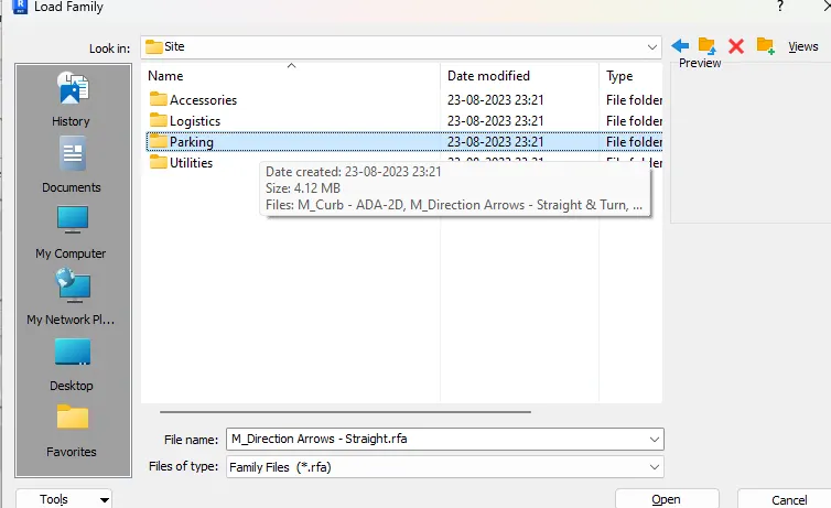
Place the element in the model.
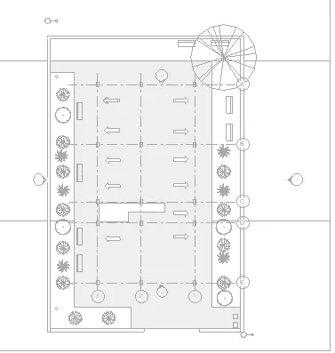
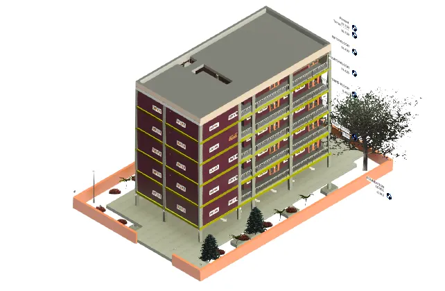
Now add parapet wall to the model on the terrace floor using wall tool.
Go to architecture tab and choose wall option.
Place the wall in the model.
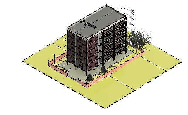
Go toMassing & Site tab and choose toposolid option.
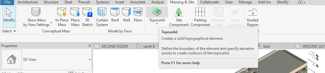
Using the draw tools create a surface.

Create a surface and specify slope arrow.
Click on finish option.
Go to 3D View to view the toposurface.
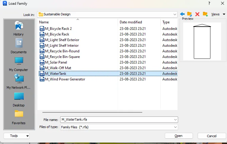
Go to load family and select sustainable design category.
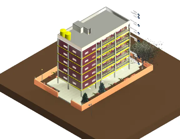
Now select water tank option from the list and place it in the model.
Result:
The components required for architecture model of the residential building such as walls, furniture, lighting, stairs, and exterior elements are included in the model.
5. Answer:
Aim: To create a set of drawings in an architectural and structural model through sheet templates.
Introduction:
Creating sheet templates for the following:
<!-- [if !supportLists]-->a. <!--[endif]-->Floor Plans with Annotations
<!-- [if !supportLists]-->b. <!--[endif]-->Elevations
<!-- [if !supportLists]-->c. <!--[endif]-->Sections
Procedure:
Open the Revit software.
Open the previously created Revit project file.
Add text and dimensions to the floor plans using Annotate tab.
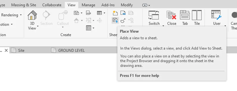
Go to the view tab and choose sheet option.
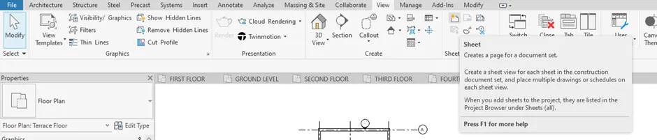
Create new sheet.
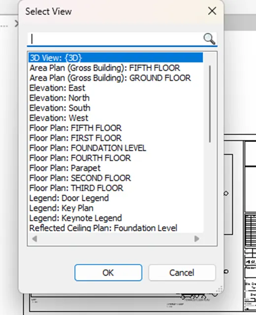
Place the view in the sheet.
Select the view and click on ok.
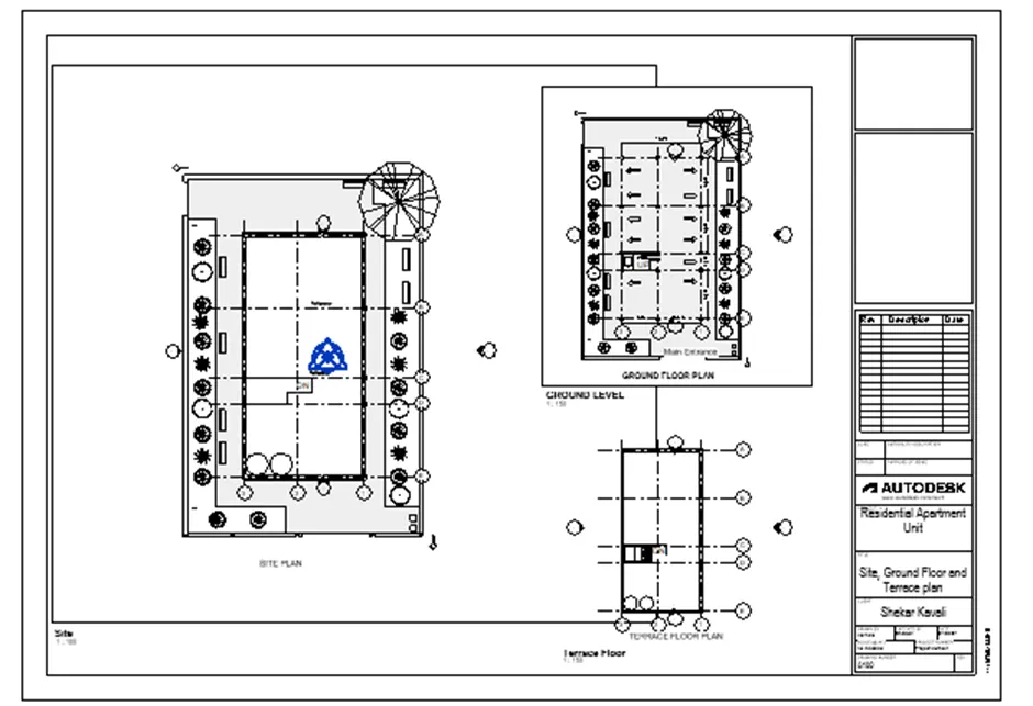
Floor Plans
Site, Ground floor and Terrace plans:
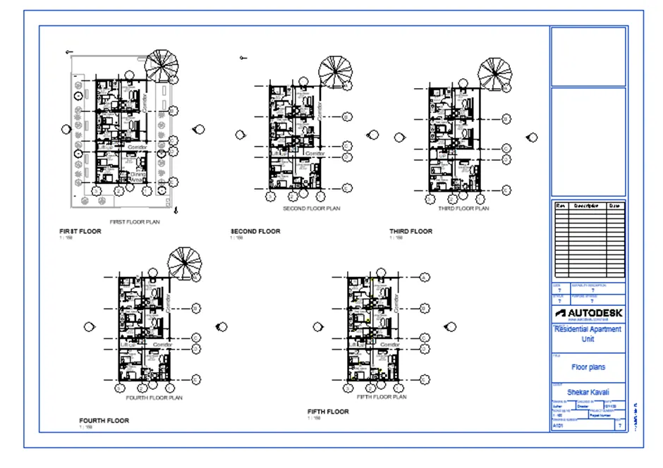
1st, 2nd, 3rd, 4th and 5th floor plans:
Elevations
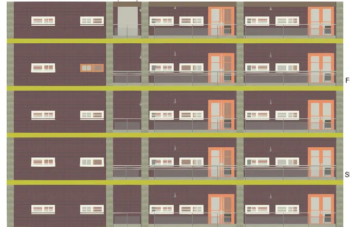
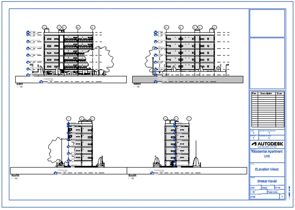
Select the East, West, North, and South elevation views and place them in the sheet.
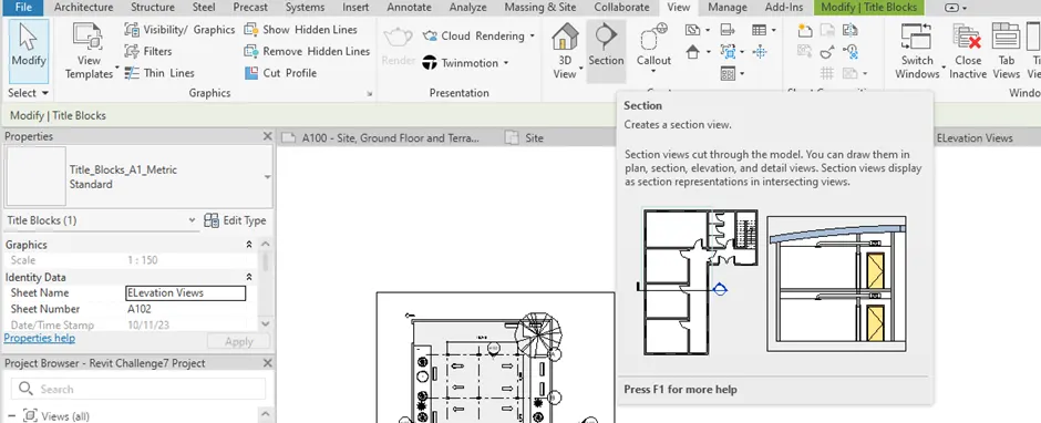
Go to View tab and choose section option from create panel.
Create section lines and view the sections in 3D view.
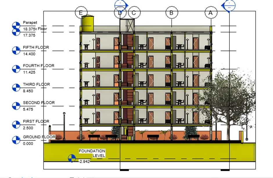
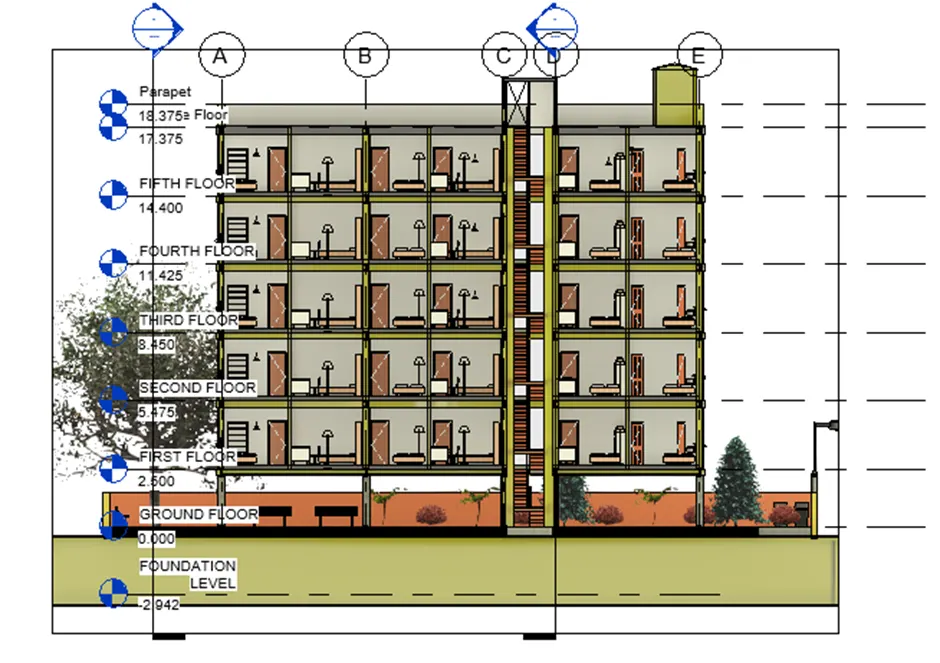
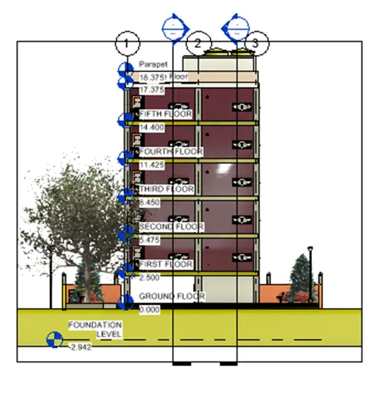
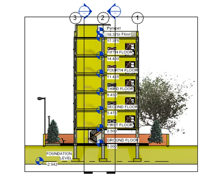
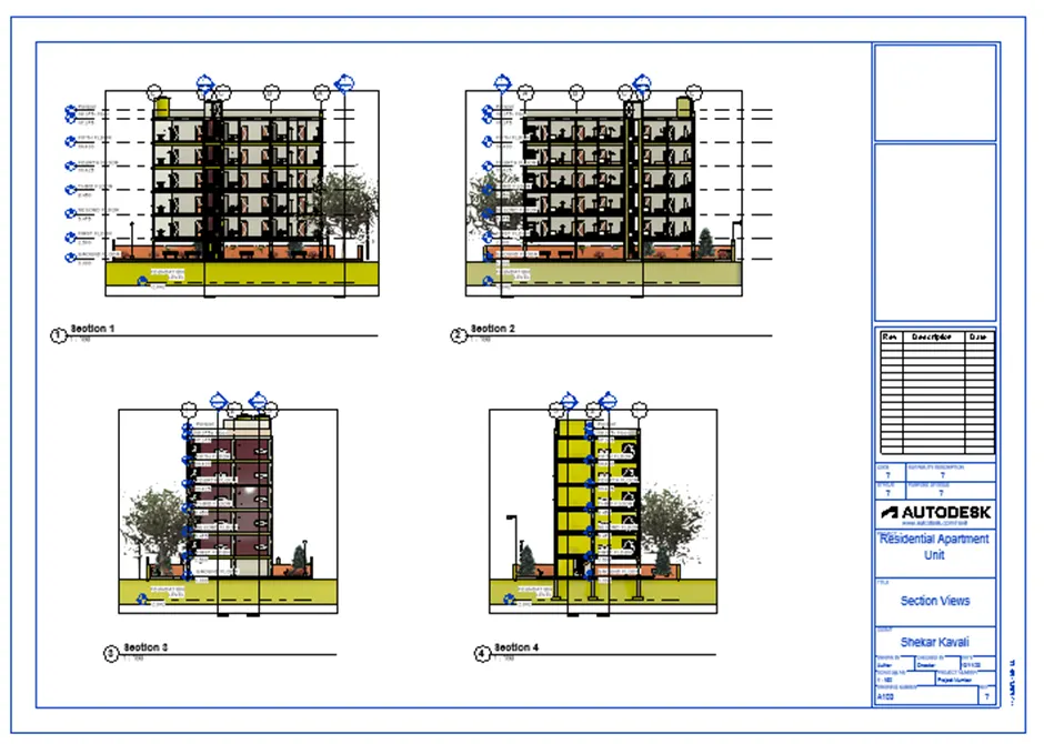
Now create new sheet and place the section views in it.
Result:
A set of drawings of architectural and structural model are created through sheet templates.
6.Answer:
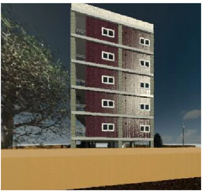
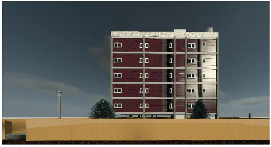
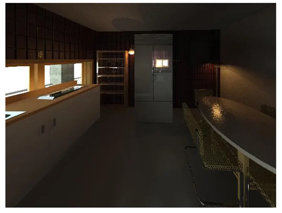
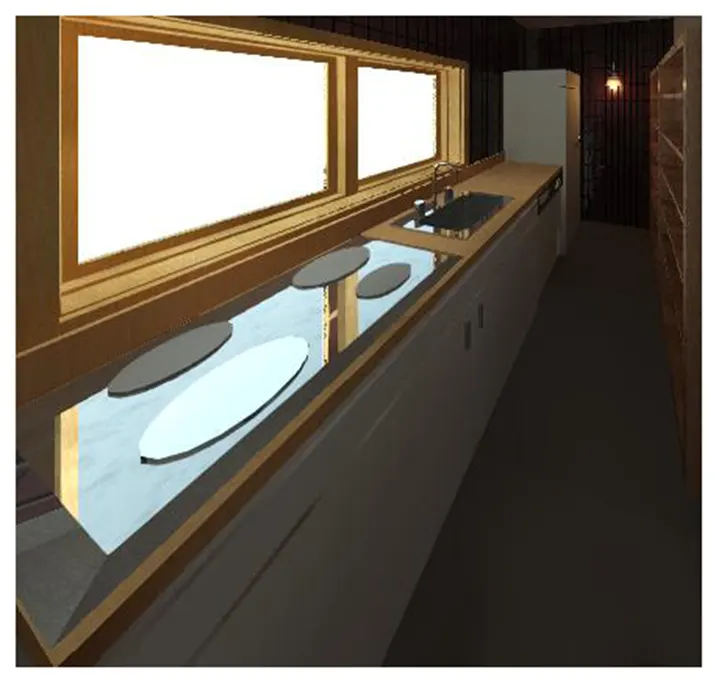
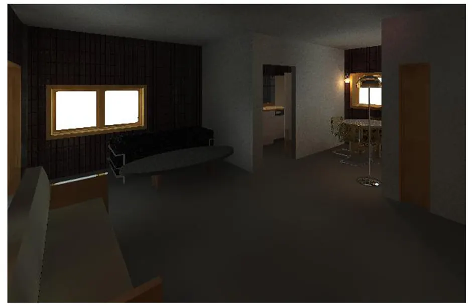
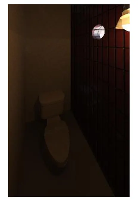
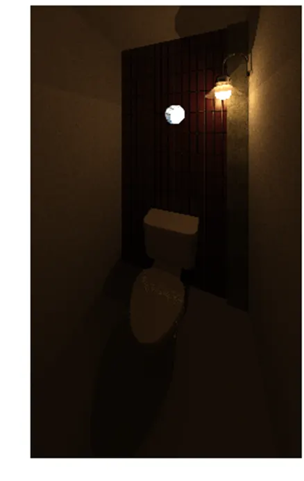
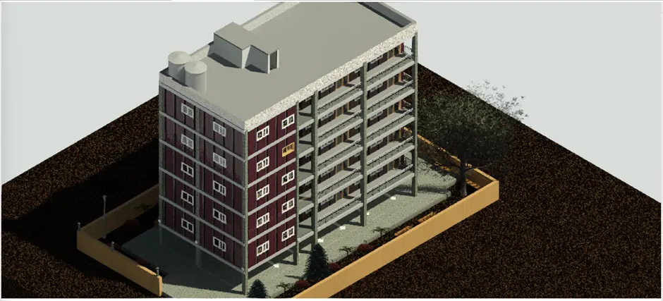
Aim: To create rendered images of the 3D model using rendering settings and including them to the sheets.
Introduction:
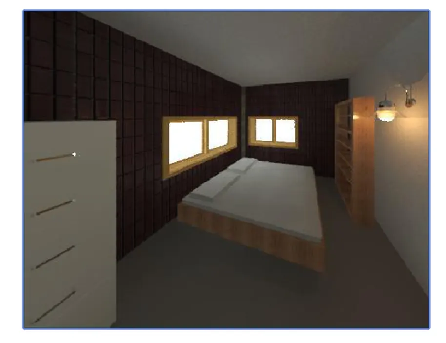
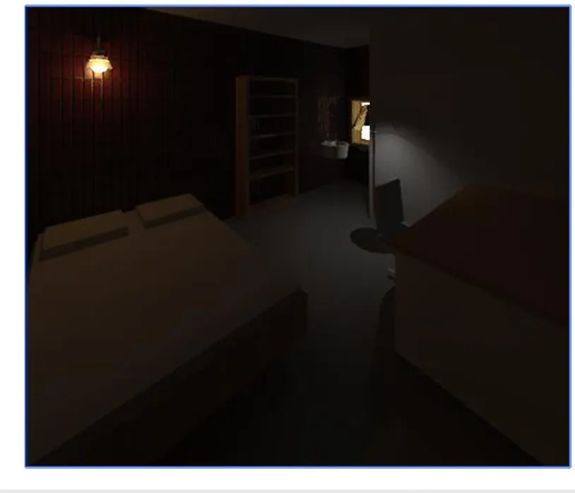
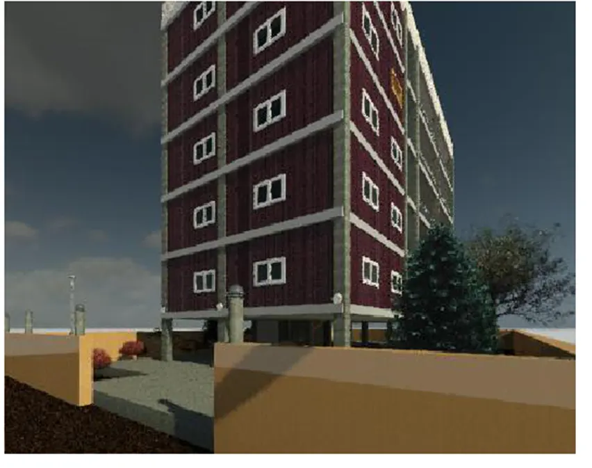
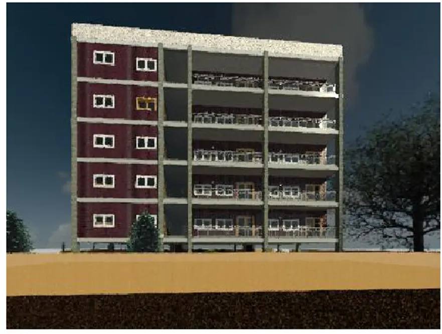
Creating rendered images of the following:
Rendering from interior rooms
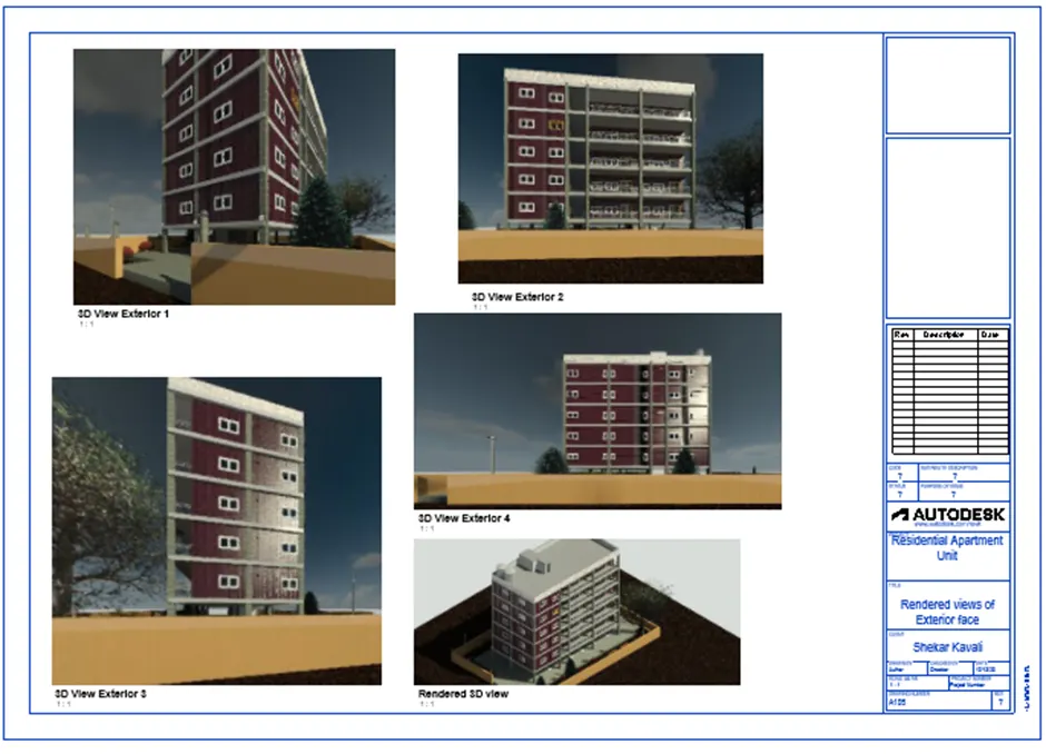
Rendering from out showing topographic features
Rendering through structural framing
Procedure:
Open the Revit software.
Open previously created project model.
For rendering process to be done, camera tool is used.
Go to view tab and drop down the 3D view option then select camera option.
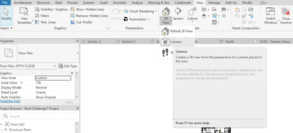 Place the camera in position in interior rooms and 3D create views.
Different 3D views:
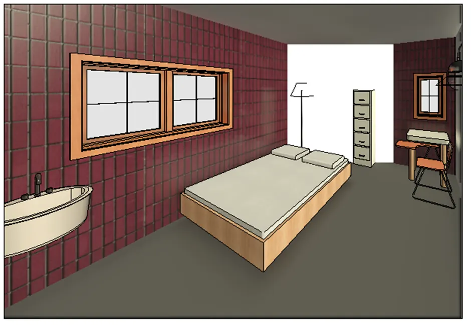
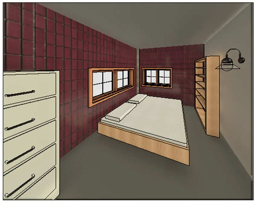
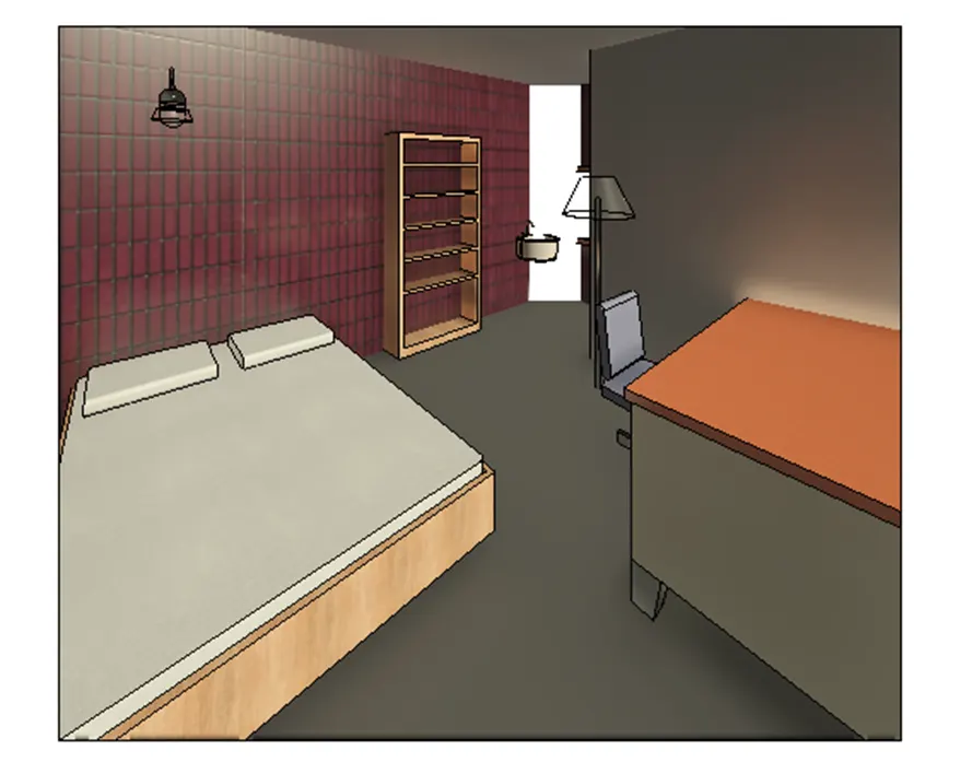
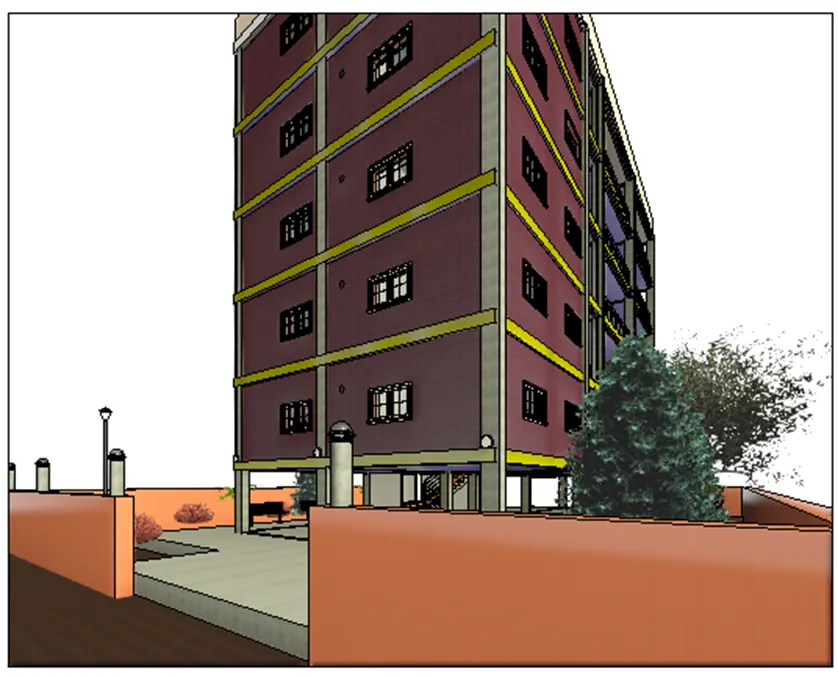
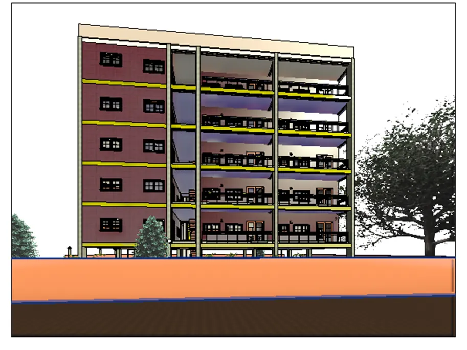
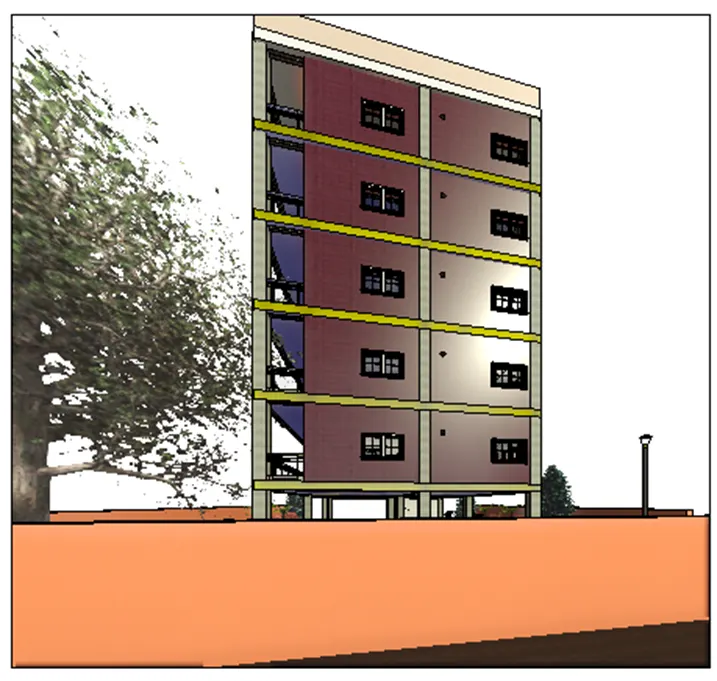
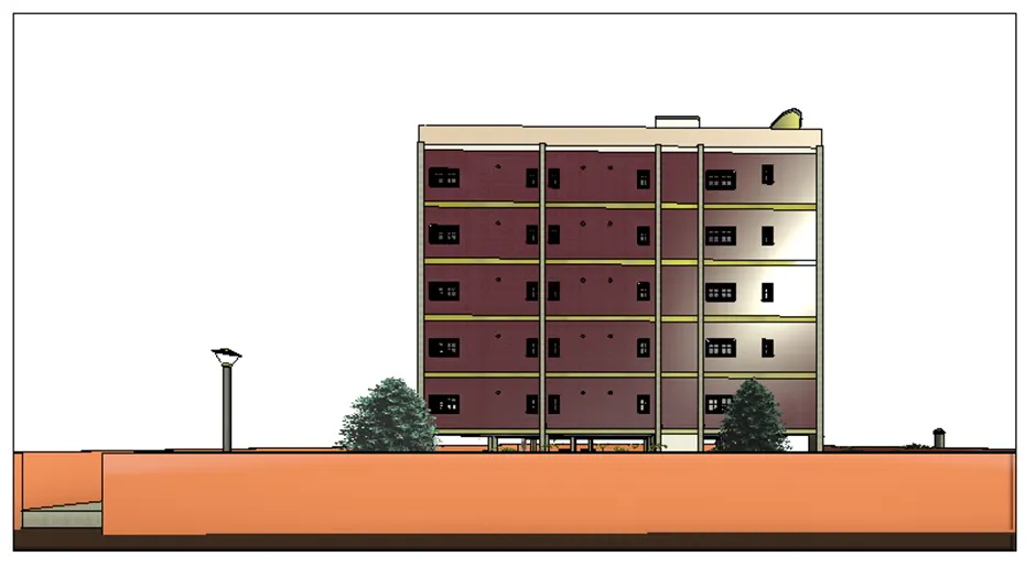
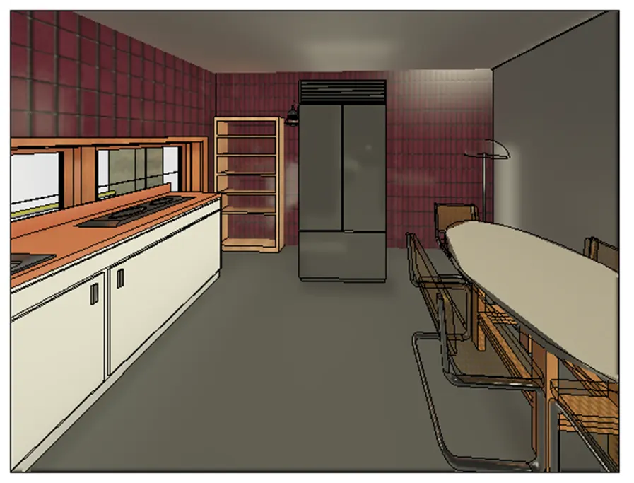
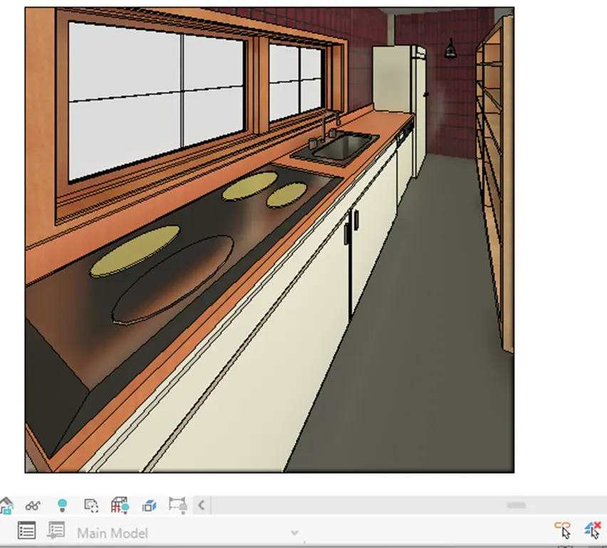
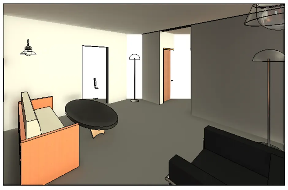
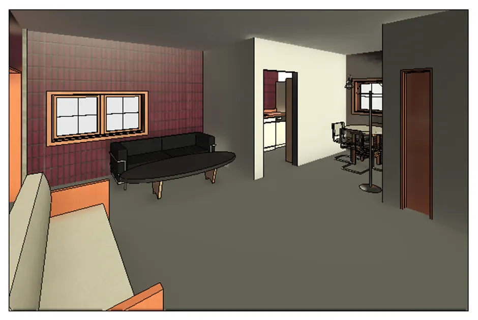
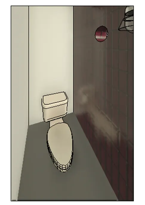
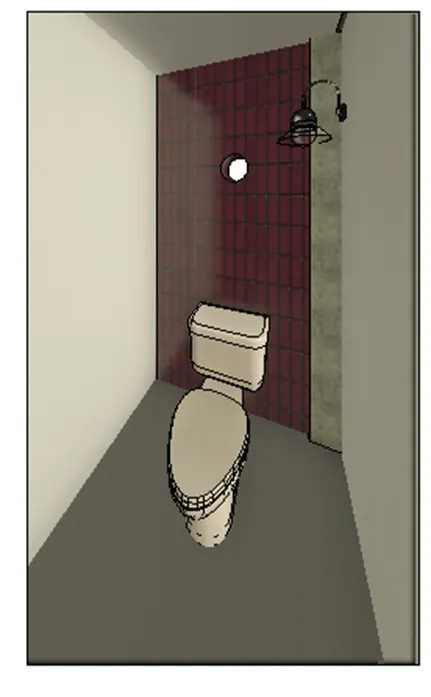
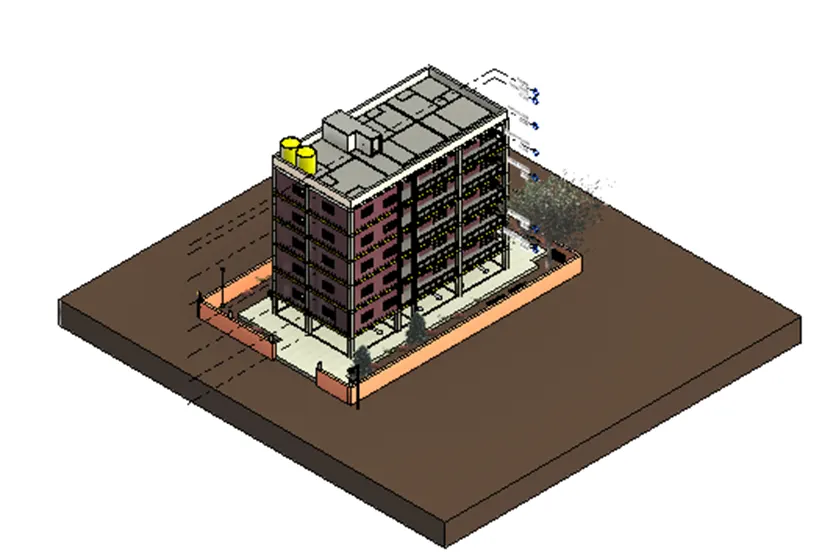
Now select the view and then go to view tab.
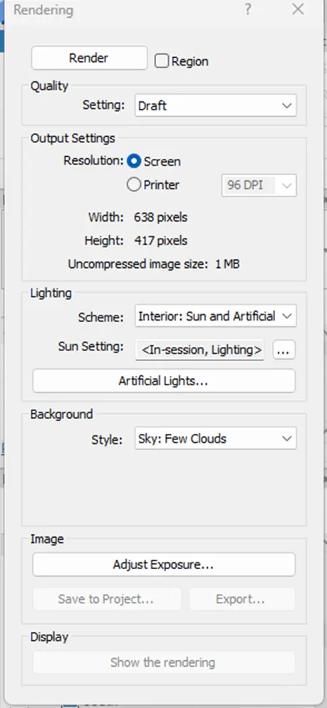
Choose render option from presentation panel.

Now the following dialog box appears.
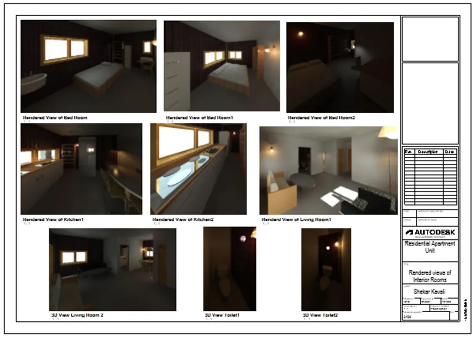
Rendered views:
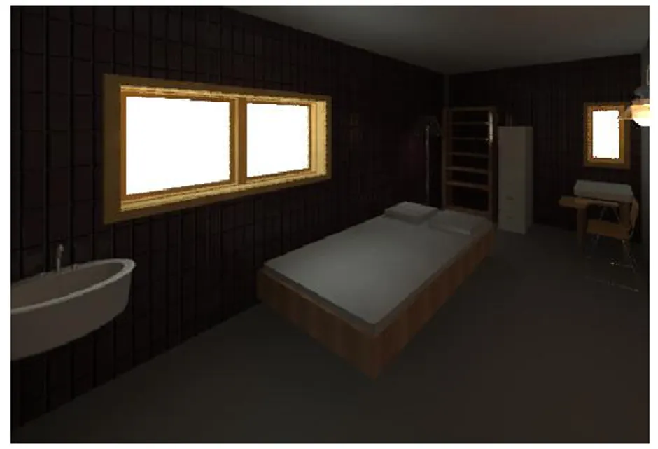
 Go to view tab and select sheet option.
Create new sheet.
Place the rendered views in the sheet.
Rendered views of Interior Rooms are placed in sheet.
Result:
The rendered images of the 3D model using rendering settings are created and included them to the sheets.
7. Answer:
Aim: To print the set of drawing sheets created from the architecture and structure model.
Procedure:
Open Revit software.
Open previously created project file.
Go to project browser and open a sheet template.
Now choose the print option.
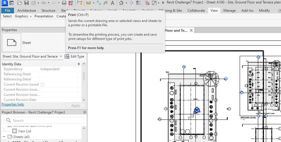
Print dialog box appears:
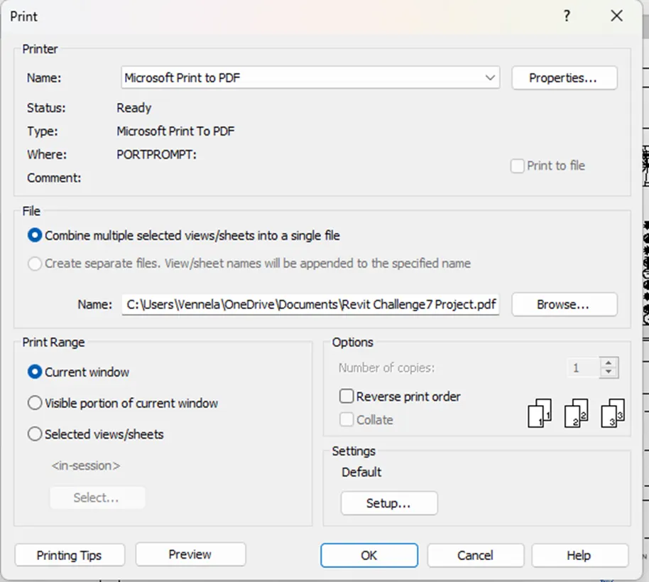
Adjust the settings and click on OK.
Now save the print output dialog box appears.
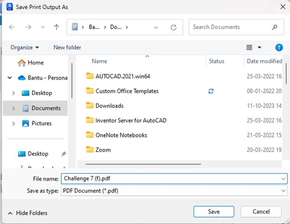
Add file name, select the destination folder and then click on save.
Similarly print all the sheets created in the project.
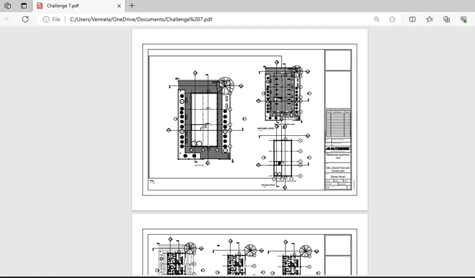
Result:
The set of drawing sheets from the architecture and structure model are created as a pdf file using print option.