3D Creation of Ceiling, Roof, Architectural plan, Structural plan, Sectional view, Elevation view and Camera specific view for a house plan using REVIT
1.Answer:
Aim: To model a ceiling from the architecture tab above the walls at the first-floor level of a residential unit.
Introduction:
The Ceiling is the surface which covers the room and hides the floor and roof. In Revit there is a dedicated Ceiling tool to model a ceiling element. Before creating a ceiling, it is necessary to model the walls so that an enclosed boundary will be developed. By choosing wall boundaries ceilings are modelled.
Procedure:
Open Revit software.
Open the previously created file.
Choose first floor option from floor plans in the project browser.
Go to Architecture tab and select ceiling option.
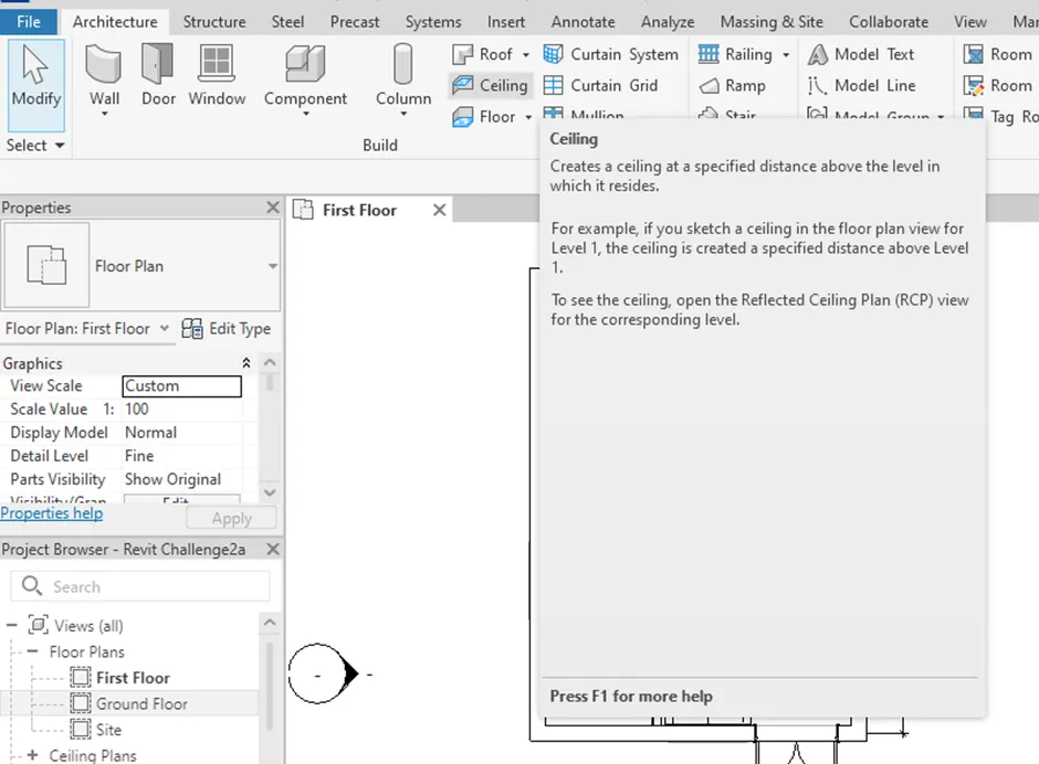
Now select Sketch Ceiling option.
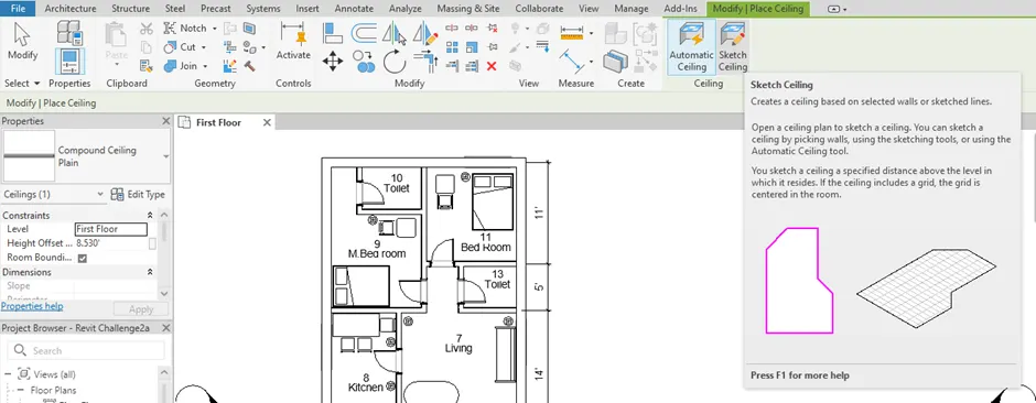
Choose pick line option from draw panel.

Now choose the boundaries of the walls in the layout.
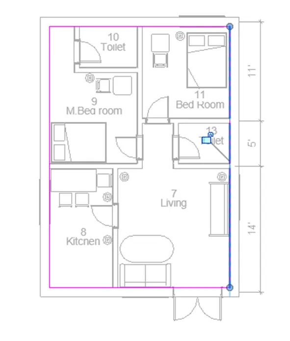
Click on finish edit mode option.
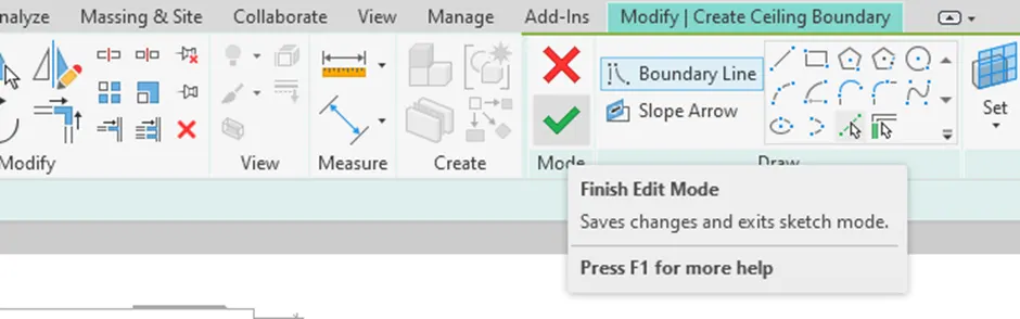
The ceiling has created. To view created ceiling, go to 3D view option.
Result:
A ceiling is created above the walls at the first-floor level of a residential unit by using Architecture tab.
2.Answer:
Aim: To model a roof above the ceiling by selecting the footprints of the ceiling and adjusting the roof slope to 10 degrees.
Introduction:
Revit has a dedicated Roof tool to create a roof over the floor. We can access the tool through the Architecture tab and we can modify the properties of the roof using properties browser.
Procedure:
Open the Revit software.
Open the previously created file.
Choose first floor option from floor plans in the project browser.
Go to Architecture tab and select Roof option.
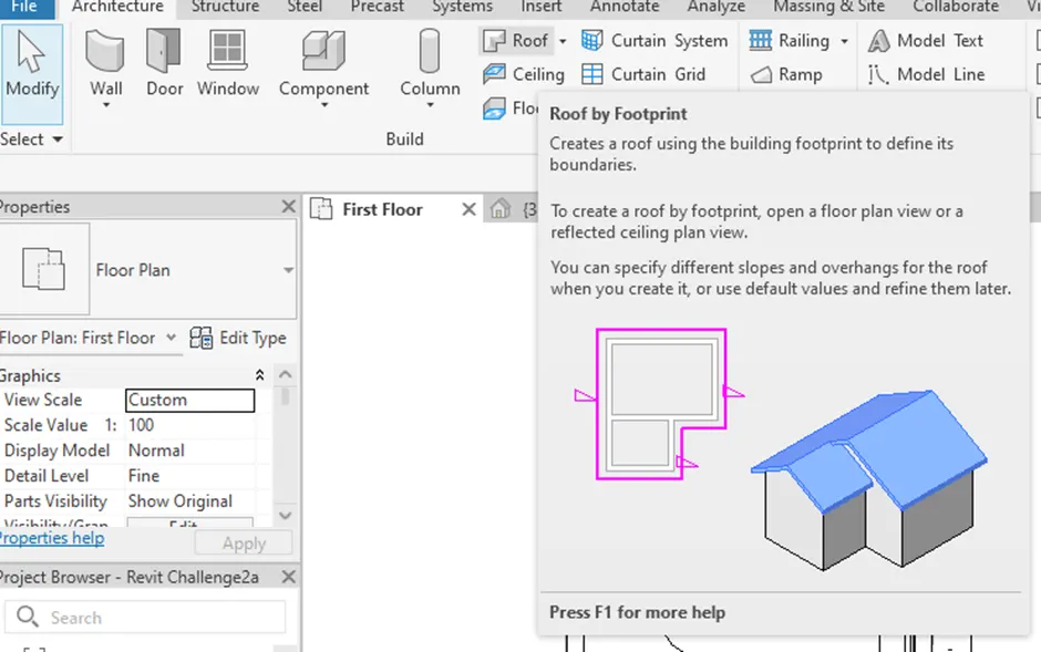
Drop down the Roof option.
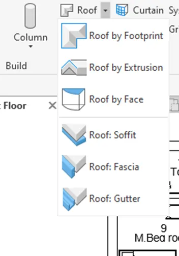
Select Roof by Footprint option.
Now select pick line option from the draw panel.
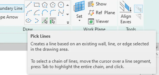
Select the edges of walls by using pick line option.
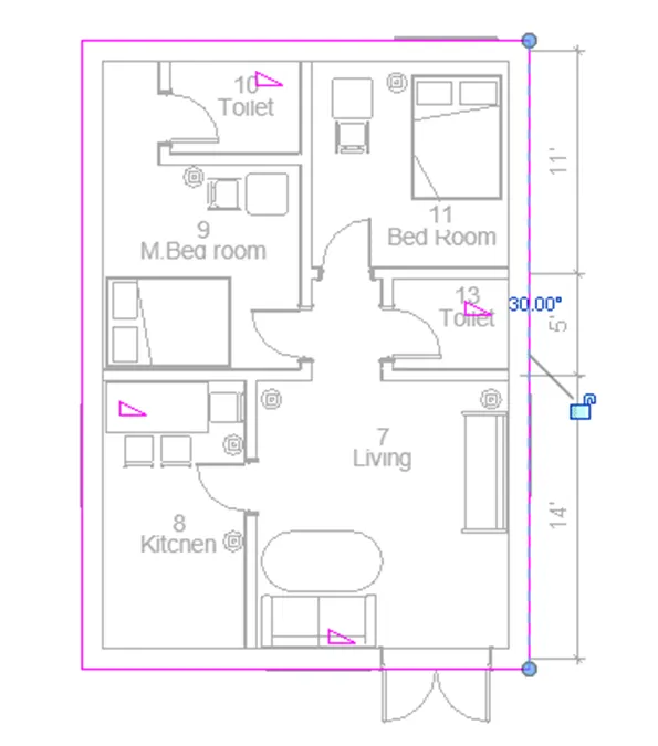
Click on finish edit mode option.
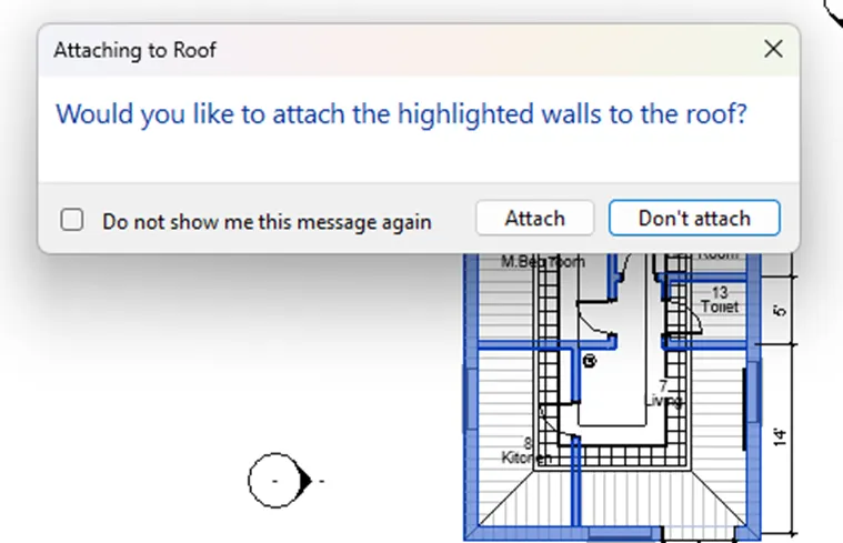
The following dialog box appears, now click on Attach option.
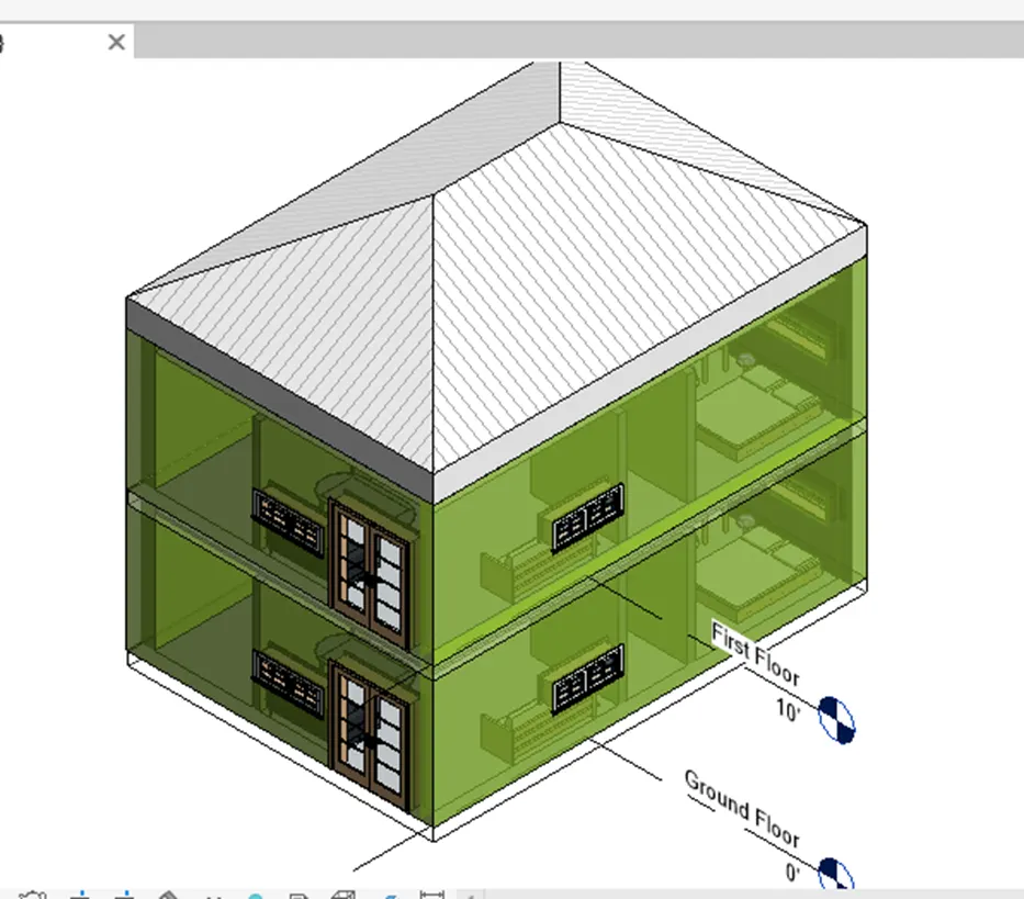
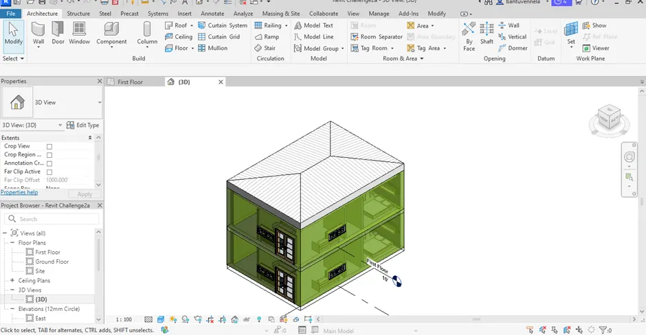
The roof has created. To view created ceiling, go to 3D view option.
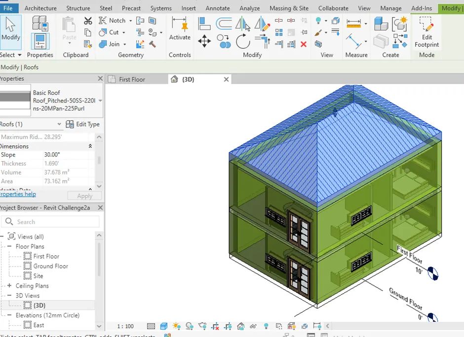
To change the slope of the roof, click on the created roof.
Now go to properties browser and change the slope value.
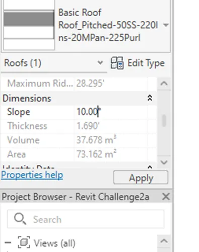
Enter the slope value as 10 degrees and click on apply.
The slope of roof has changed.
Result:
A roof above the ceiling has been created by selecting the footprints of the ceiling and adjusting the roof slope to 10 degrees.
3.Answer:
Aim: To create plan views for ground floor level and first-floor level including all the walls, floors, components and separating the architectural and structural plans of the residential unit.
Procedure:
Open the Revit software.
Open the previously created file.
Go to view tab and click on plan views.
Drop down the plan views option and click on floor plan.
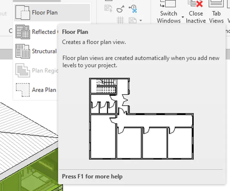
The following dialog box appears, now click on edit type option.
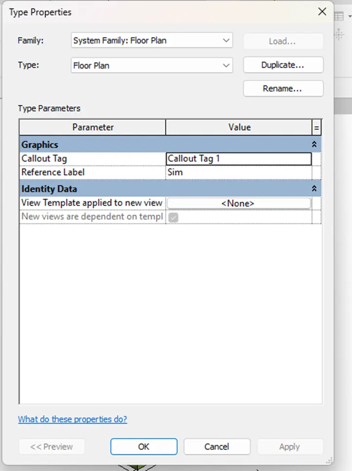
Click on ok.
Architectural plan of First floor:
< alt>
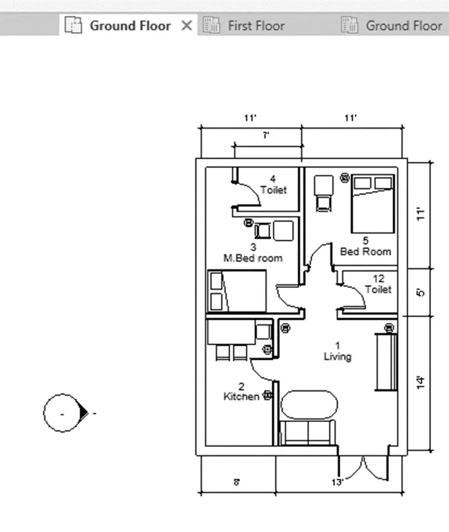
Architectural plan of Ground floor:
Now to view structural plan, again go to view tab and select plan views option.
Drop down the plan views and select structural plan option.
The following dialog box appears.
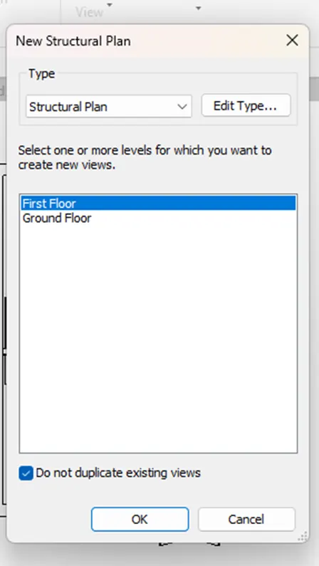
Select the floor level and click on ok.
Structural plan view of First floor:
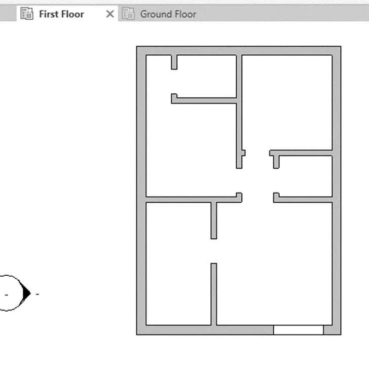
Structural plans of first floor and ground floor are created.
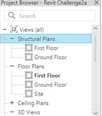
Result:
The plan views for ground floor level and first-floor level including all the walls, floors, and components are created. Architectural and structural plans of the residential unit are separated.
4.Answer:
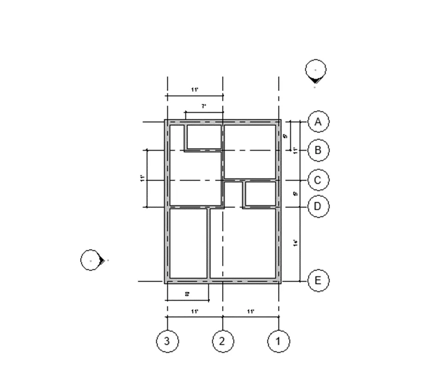
Aim: To add dimensions using annotate toolbar to all the walls and floors with reference to the longitudinal and transverse grids.
Procedure:
Open the Revit software.
Open the previously created file.
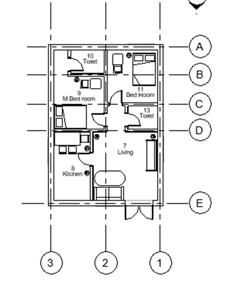
Open the Architectural plan.
</>
< class>To add dimensions, go to the Annotate tab and select linear or aligned dimension option.
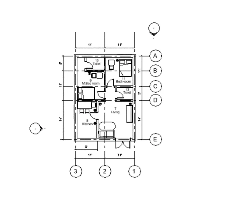
Now open the structural plan.
Go to the Annotate tab and select linear or aligned dimension option.
Place the dimensions in the structural plan with reference to longitudinal and transverse grids.
Result:
Dimensions are added to all the walls and floors with reference to the longitudinal and transverse grids using annotate toolbar.
5.Answer:
Aim: To create a sheet template from the view tab and adding appropriate views by adjusting the parameters on the sheet.
Procedure:
Open the Revit software.
Open the previously created file.
Go to view tab and click on sheet icon in the sheet composition panel.
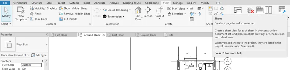
New sheet dialog box appears.
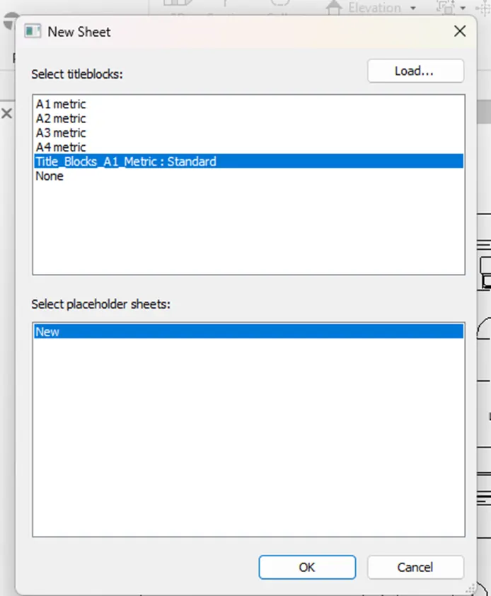
Select the sheet size and click on ok.
A new sheet will be created.
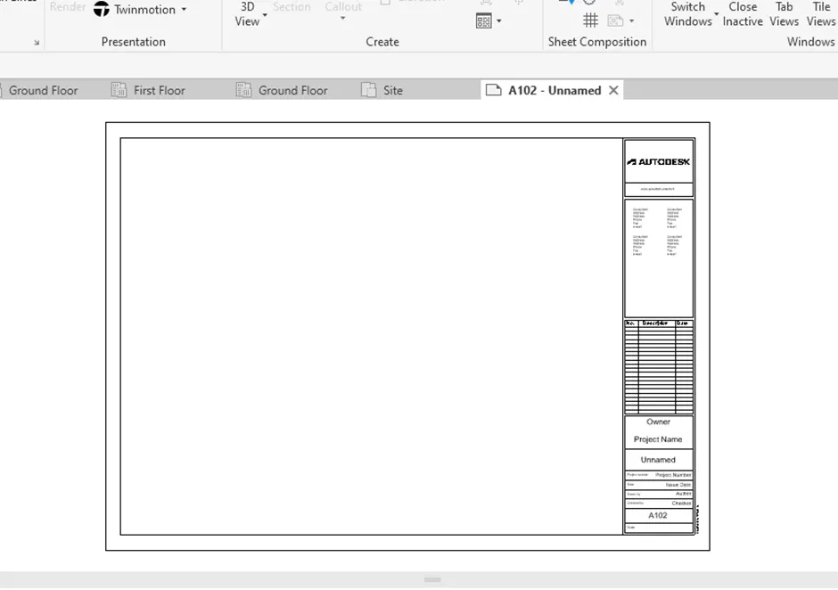
Now from the project browser drag the view to the sheet.
Adjust the view in the sheet by changing the scale of the view from the properties browser.
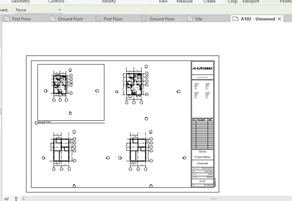
Rename the sheet with appropriate name.
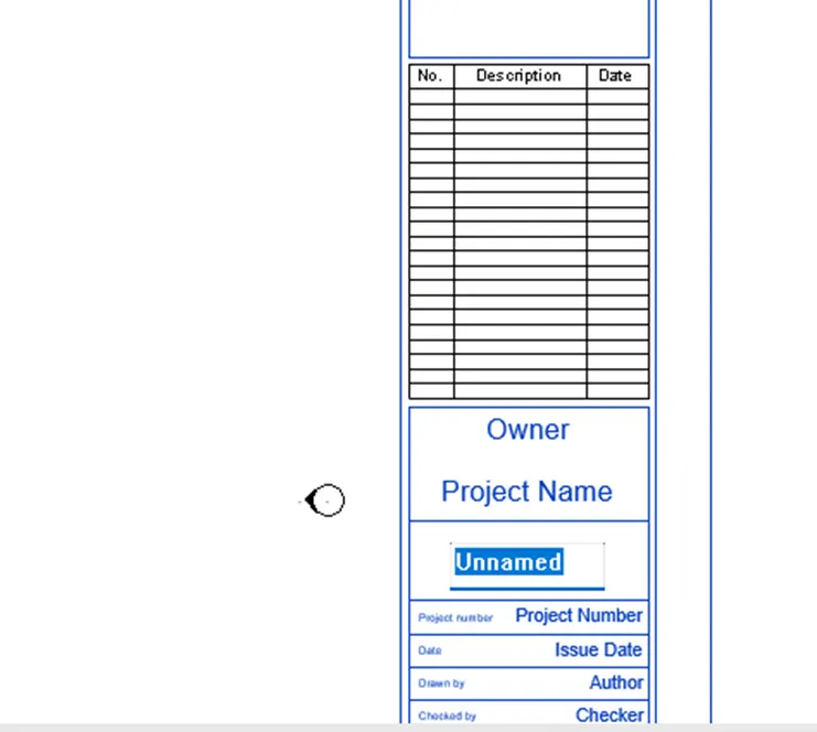
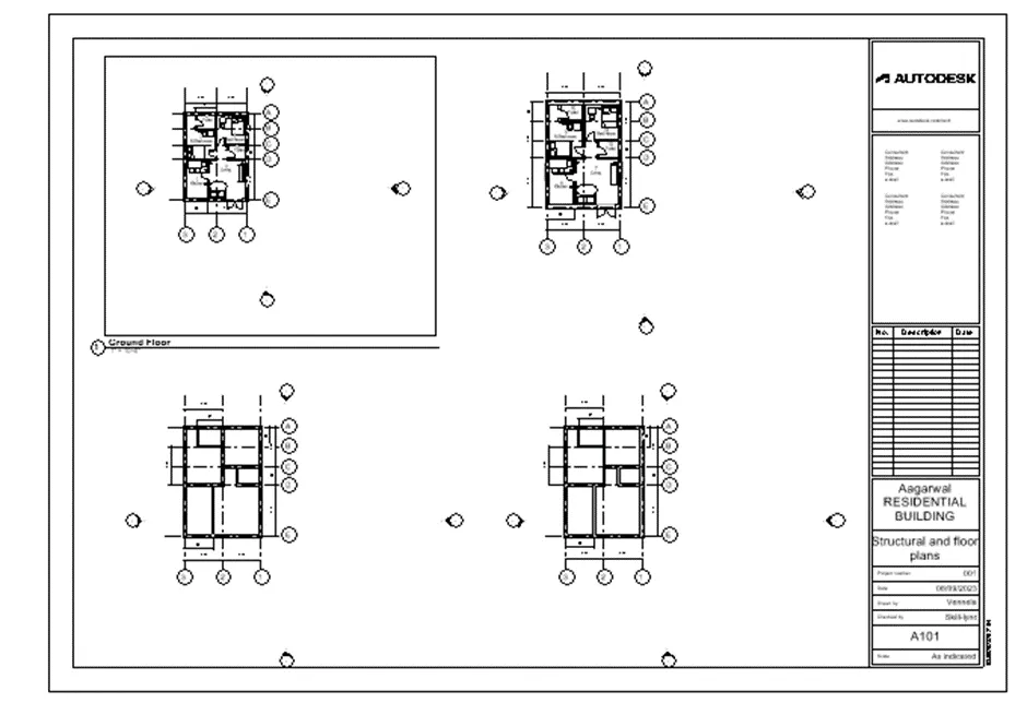
Add the details in the title block of the created sheet.
Result:
A sheet template from the view tab is created and appropriate views are added by adjusting the parameters on the sheet.
6.Answer:
Aim: To create the elevation views of the building from East, West, North and South direction by using Elevation tab.
Procedure:
Open the Revit software.
Open the previously created file.
Go to view tab and click on elevation.
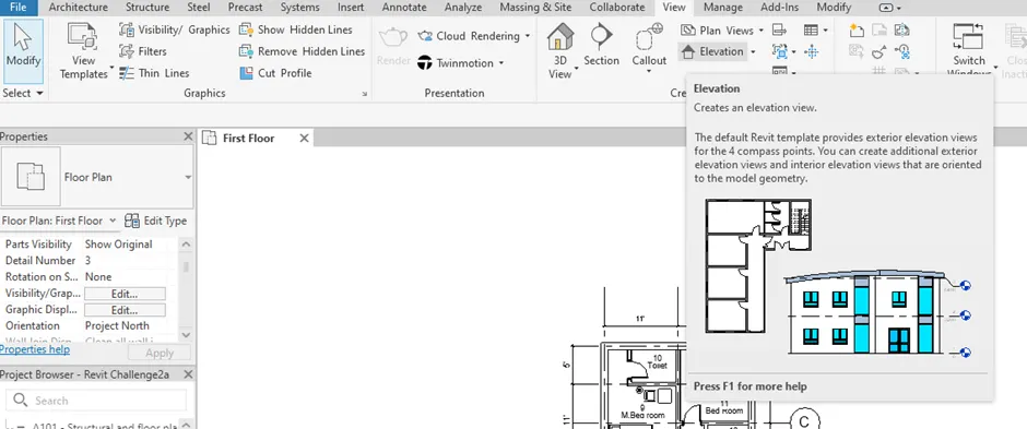
Drop down the option and click on elevation.
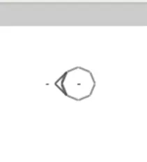
Place the elevation symbol towards the required direction.
Now rename the elevation as its direction for eg East.
Similarly place the symbol and rename the elevation views as West, North and South.
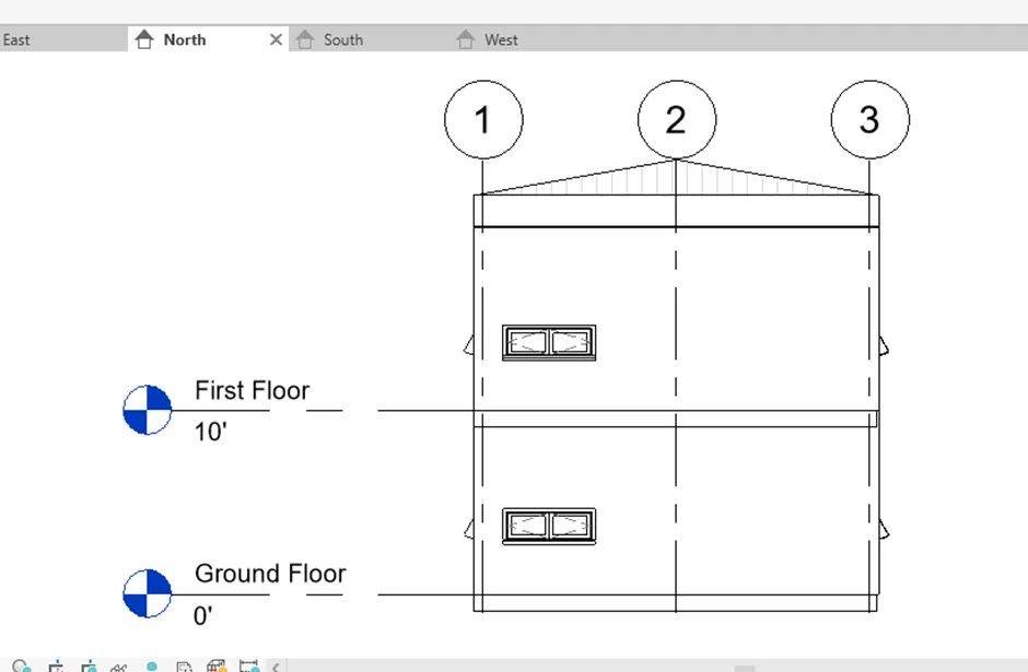
North elevation view:
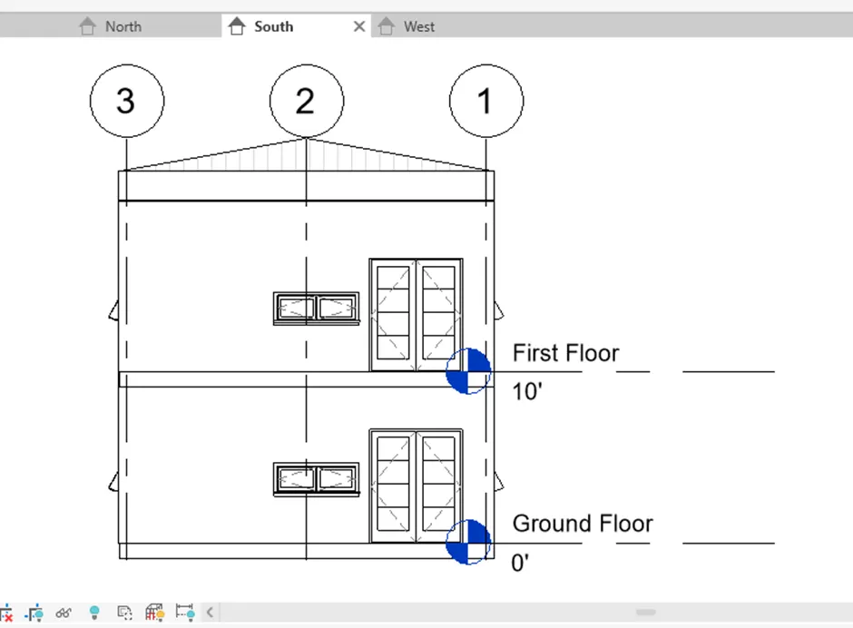
South elevation view:
Result:
The elevation views of the building from East, West, North and South direction are created by using Elevation tab.
7.Answer:
Aim: To produce the section cut through each room by cutting across longitudinally or in a transverse direction.
Procedure:
Open the Revit software.
Open the previously created file.
Go to view tab and select section option.
Cut the room in longitudinal or transverse direction.
Section is created and we can view it from the project browser.
Rename it as the name of the room for example kitchen.
To view the section, double click on created section in the project browser.>
< class>
Similarly create section views of each room.
Section view of living room:
Section view of bed room:
< />< />Section view of master bed room:
Section view of Toilet:
</>
< class>Result:
The section cut is created by cutting each room across longitudinal and in a transverse direction.
8.Answer:
Aim: To classify the views, Plan views, Section views, and Elevation views to Design or Document category using Properties browser.
Procedure:
Open the Revit software.
Open the previously created file.
Go to the project browser.
To classify the views click on each category in the project browser.
Classifying the Structural Plans:
>
< class>
Classifying the Ceiling plans:
Classifying the 3D Views:
Classifying the Elevation Views:
Classifying the Section Views:
Result:
Plan views, Section views, and Elevation views are classified to Design or Document category using Properties browser.
9.Answer:
Aim: To create multiple sheets using the produced sheet template.
Procedure:
Open the Revit software.
Open the previously created file.
Go to view tab. Click on sheet icon.
New sheet dialog box appears.
Choose the sheet and click on ok.
New sheet will be created.
Select the Ground floor Architectural plan view and drag the view on to the sheet.
Place and adjust the view properly.
>
< class>
Similarly, creating sheet A102- First Floor Architectural plan.
>
< class>
Creating sheet S 101- Ground Floor Structural Plan:
Creating sheet S 102- First Floor Structural Plan:
Creating sheet A 201- North-South Elevations:
>
< class>
Creating sheet S 201- Section views:
Creating sheet S 202- 3D views:
Result:
Multiple sheets are created by placing different views using sheet template.
< />< />
10.Answer:
Aim: 1. To create a 3D view in living room, dining room, and bed room by placing a camera.
2. To create a new set of sheets to place the 3D view images based on the created views.
Procedure:
Open the Revit software.
Open the previously created file.
Creating 3D views of different rooms by placing camera:
Go to View tab and drop down the 3D view.
Choose camera option.
Place the camera in a position such that the components in the room are visible.
< />< />The camera view will be created.
Camera view of Living Room:
>
< class>Rename the camera view in project browser.
Camera view of Dining room:
Camera view of Master Bed Room:
< />< /> Camera view of Bed Room:
</>
< class>Creating a new set of sheets to place the 3D view images:
Go to view tab. Click on sheet icon.
New sheet dialog box appears.
Choose the sheet and click on ok.
New sheet will be created.
Place the 3D images created by camera on the sheet.
Sheet S 203- 3D image of Living room:
</>
< class>Sheet S 204- 3D image of Dining room:
</>
< class>
Sheet S 205- 3D image of Bed room:
Result:
The 3D view in living room, dining room, and bed room are created by placing a camera and the views/images are placed in new set of sheets.