Week 1 Challenge
1.1 Answer:
Aim: To write the steps involved to upload a .std file through web mail.
Procedure:
Open STAAD Pro software and locate the share option available on the introduction screen.
After clicking on the share button, select send mail option.
Then, browse the .std file on your machine and send it.
1.2 Answer:
Aim: To list out the different materials that can be designed using STAAD Pro.
Procedure:
Open Staad Pro software.
Create a new project and add name and location for the project.
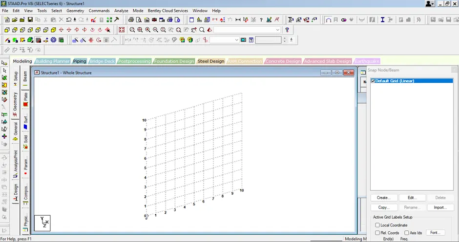
Go to commands tab and select material constants option from the list.
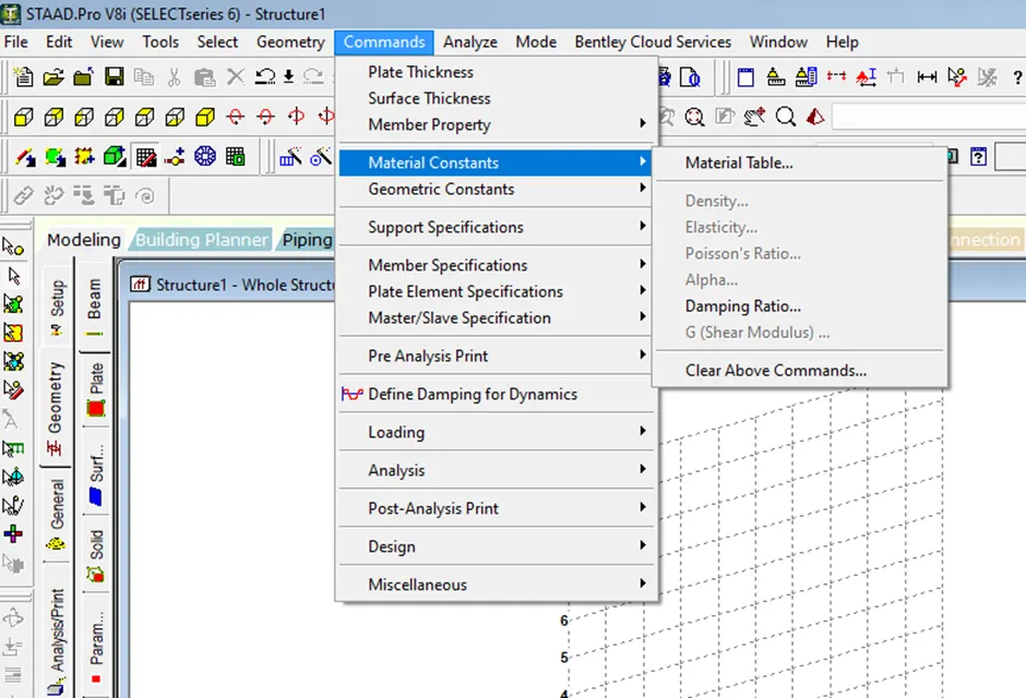
Now select Material table option to view the list of materials available in Staad.Pro.
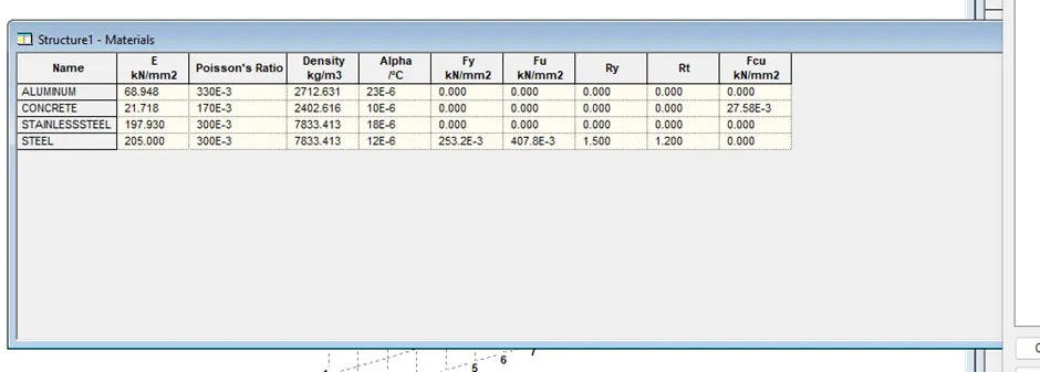
Result: Different materials available in Staad.Pro are listed successfully.
1.3 Answer:
Aim: To know about capturing images in SAAAD Pro.
Procedure:
Yes, it is possible to capture images in STAADPRO by the following way.
Open Staad Pro software.
Create a new project and add name and location for the project.
Go to Edit tab and choose take a picture option.
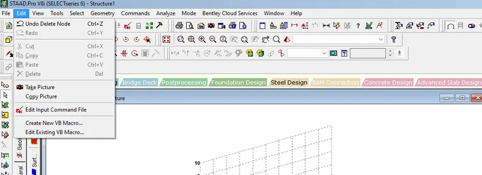
The following dialog box appears.
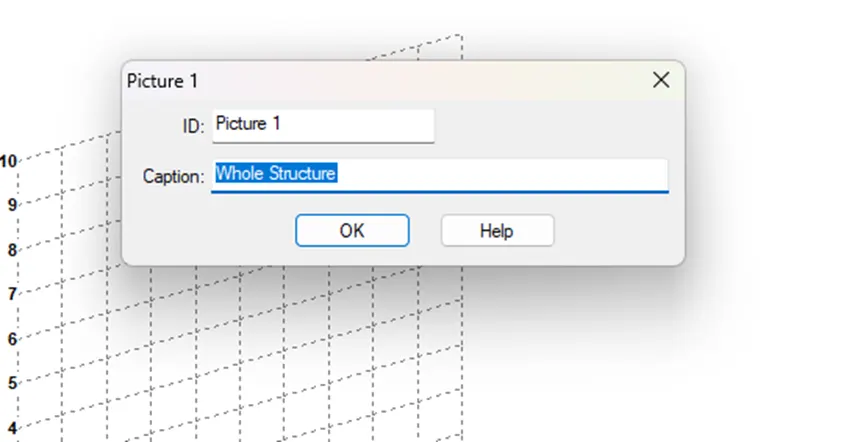
Click on ok to save the picture.
Result: We can take the pictures of model or structure created in Staad.Pro.
1.4 Answer:
Aim: To list the three ways by which we can create a model.
Procedure:
Three ways of creating a model are:
· Creating the model by using the STAAD.Pro Physical Modeler Interface.
· Creating the model using the traditional STAAD.Pro analytical modelling Interface.
· Creating the model by using the command file.
STAAD Pro comes with accurate, speedy, error free, and graphical methods to accomplish the creation of Geometry.
· Using snap grid method
· Using copy/cut with paste method
· Using run structure wizard
· Using DXF import file import function
Result: Three ways of creating a model are listed.
1.5 Answer:
Aim: To write the steps followed to assign properties in a model.
Procedure:
Assigning the properties means defining the members material and size.
For assigning properties:
Open Staad Pro software.
Create a new project and add name and location for the project.
Go to property page in Ribbon tab.

The following dialog box appears.
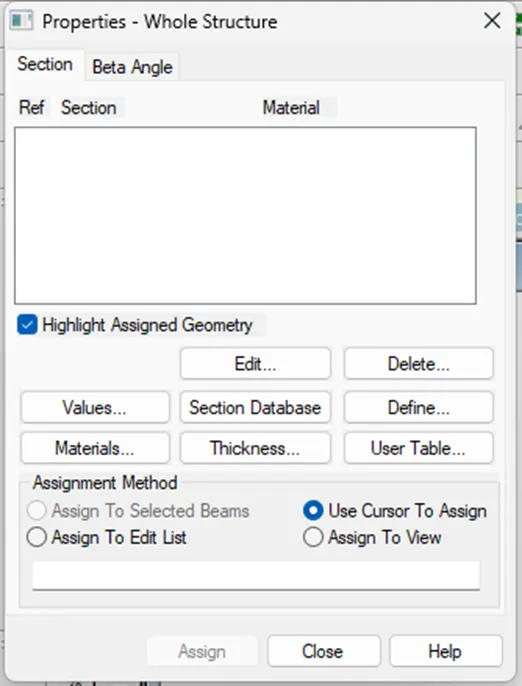
Click on Define option.
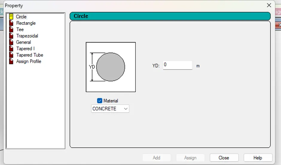
Choose the property and then click on Assign.
Similarly, select materials option and select one material.
To add thickness to the member, click on thickness option.
After selecting all the properties, choose any one assigning method and then click on Assign and then close.
Result: Steps followed to assign properties in a model are mentioned.
2.1 Answer:
Aim: To list any six design parameters involved in RCC design.
Procedure:
Six design parameters involved in RCC design are:
· Clear cover for reinforcement
· Depth of cross section
· Compressive strength of concrete (FC)
· Yield strength for main and secondary reinforcement (FY)
· Maximum and minimum main reinforcement bar size
· Width of cross section
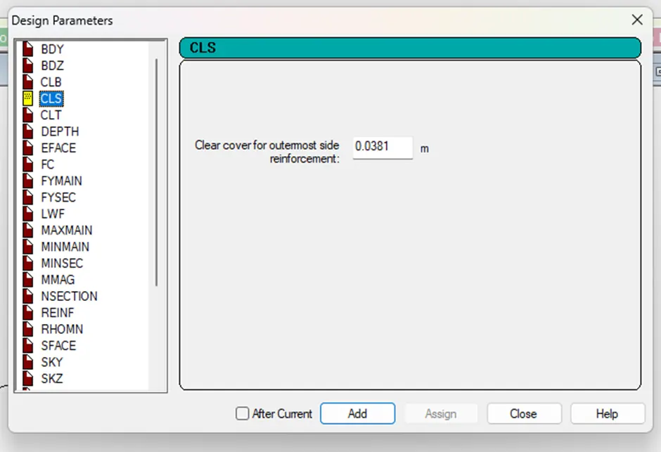
Result: Six design parameters involved in RCC design are listed.
2.2 Answer:
Aim: To know about the different cursor types available in STAAD Pro.
Procedure:
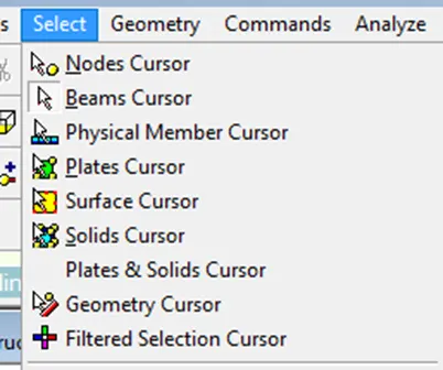
Different cursor types available in STAAD Pro are:
· Nodes Cursor
· Beams Cursor
· Plates Cursor
· Surface Cursor
· Solids Cursor
· Geometry Cursor
· Filtered Selection Cursor
All cursor types are available in Select Menu in the menu bar. These cursors are also available in the page control bar on the left side of the window
Result: Different cursors available in STAAD Pro are listed.
2.3 Answer:
Aim: To know about generating different views for a model and the steps involved in generating.
Procedure:
In STAAD Pro total 7 views are available and these can be accessed from view cubes available in the rotate toolbar.
· + Z View (Front)
· - Z View (Back)
· - X View (Left)
· + X View (Right)
· + Y View (Top)
· - Y View (Bottom)
Isometric View
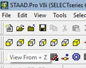
Result: Different views are generated by clicking on the views available in Rotate tool bar.
2.4 Answer:
Aim: To know the procedure to define a “Simply Supported” condition in STAAD Pro.
Introduction:
Without defining supports, STAAD.Pro will not analyze a structure. So defining a support system is essential and proper definition of support is utmost important to have actual response (moments, shear, axial loads and torsions etc.) to provide proper resistance against the response in designing or proportioning members sizes.
Procedure:
Open Staad Pro software.
Create a new project and add name and location for the project.
Create two nodes at a distance by using node cursor and create a beam by joining the two nodes using beam cursor.
Select the beam and then go to supports page in tool bar.

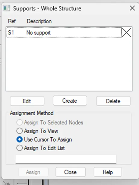
Click on create option. Create Support dialog box appears.
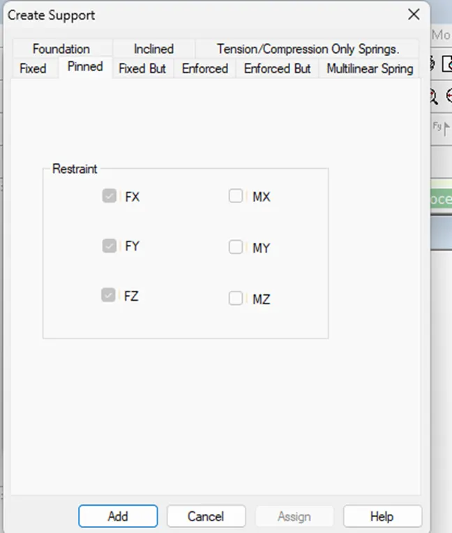
Choose pinned support and click on Add.
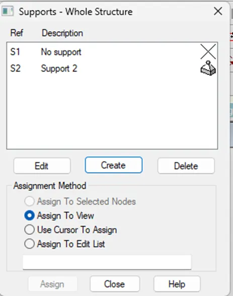
Support is added in the supports dialog box. Now, choose Assignment method and click on close.
Result: The procedure to define simply supported condition in Staad Pro is found.
2.5 Answer:
Aim: To list any five topics that we will include while creating DBR.
Procedure:
The topics that we can include while creating DBR are:
· Project name and location
· Information on the project scope
· Design Criteria
· Methodology
· Material and Equipment specifications
· Assumption, considerations and calculations
Result: Five topics that will be included while creating Design Basis Report are listed.
2.6 Answer:
Aim: To know about the term “Multi material design” of STAAD Pro.
Procedure:
STAAD Pro supports multi-material design codes such as timber, steel, cold-formed steel, concrete and aluminium.
3.1 Answer:
Aim: To know in detail about the structure systems in STAAD Pro.
Procedure:
Structure systems in STAAD Pro:
Truss: A Truss structure consists of truss members which can have only axial number forces and no bending in the members.
Plane: A plane structure is bound by a global X-Y coordinate system with loads in the same plane.
Space: A space structure, which is a three dimensional framed structure with loads applied in any plane, is the most general.
Floor: A floor structure is a two or three dimensional structure having no horizontal movement (global X or Z) of the structure. The floor framing (in global X-Z plane) of a building is an ideal example of a FLOOR structure.
Result: Structure systems in STAAD Pro are defined.
3.2 Answer:
Aim: To know about the coordinate systems adopted in STAAD Pro software.
Procedure:
There is a single Global Coordinate System in STAAD Pro, which we define the Node coordinates using it. The Global Coordinate System, appear at the lower left corner of the main window.
We use GX, GY, and GZ, to differentiate them from the Local Coordinate System X, Y and Z.
For each Beam, there is a Local Coordinate system as follows:
X, is always from Start to End along the member.
Y, is the direction of Minor principle axis.
Z, is the direction of Major principle axis.
Result: The coordinate systems adopted in Staad Pro are explained.
3.3 Answer:
Aim: To know about DBR and its uses.
Procedure:
DBR: Design Basis Report is a document that outlines the design criteria and requirements for an engineering project. It is often used as a reference during the design, construction, and commissioning phases of a project. The report includes information on the project scope, design criteria, materials, and equipment specifications, as well as other important information that guides the project’s design and implementation.
3.4 Answer:
Aim: To know about the different types of analysis options in STAAD Pro.
Procedure:
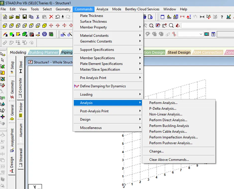
STAAD Pro Analysis can be:
· The first analysis command is Perform Analysis.
· P-Delta Analysis
· Non- Linear Analysis
· Perform Direct Analysis
· Perform Buckling Analysis
· Perform Cable Analysis
· Perform Imperfection Analysis
· Perform Pushover Analysis
From the Page Control select Analysis/Print, the following dialog box appears.
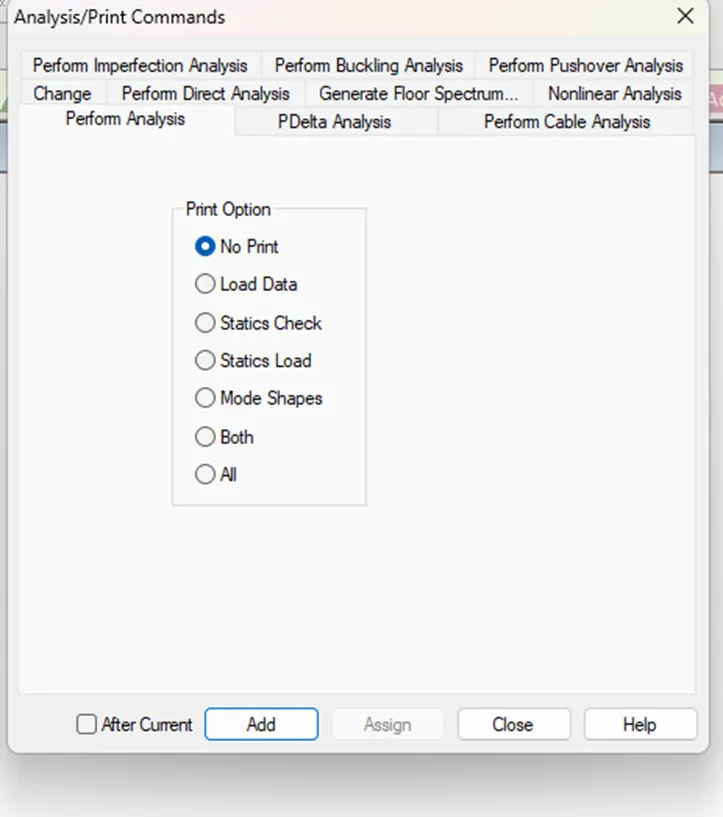
Select the type of analysis and choose any print option and then click on Add.
Result: Different types of Analysis in Staad Pro are listed.
3.5 Answer:
Aim: To know the difference between Fixed and Fixed But condition.
Procedure:
Fixed condition: Fixed support is the most rigid type of support or connection. It constraints the member in all translations and rotations. (Fixed supports are restrained in all six degrees of freedom)
Fixed But condition: The fixed but support condition is used to allow the user to define which degrees of freedom of a node are free and which are fixed.
Practical:
Aim: To create a STAAD Model with the following Specifications
a. A beam of span 16 m
b. Support: Fixed on one end and Roller support (Horizontal) on the other end
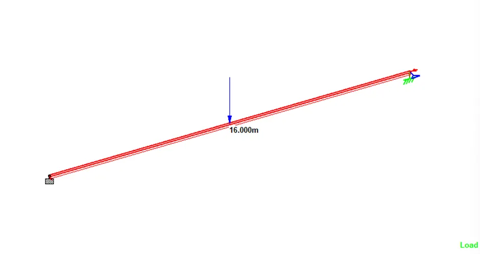
c. A point load of 50 kN at the mid-point.
d. Draw SFD and BMD using software.
Procedure:
Open Staad Pro software.
Create a new project and add name and location for the project.
Click on Edit option in Snap Node/Beam dialog box.
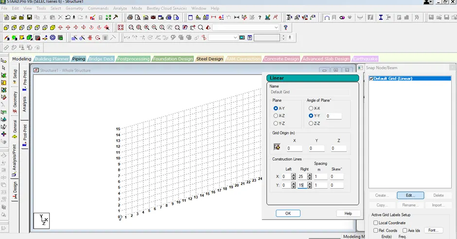
Change the settings if needed and click on OK.
Creating beam
Insert two nodes at a distance of 16 m between them.
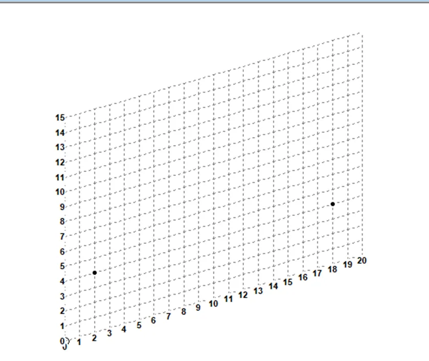
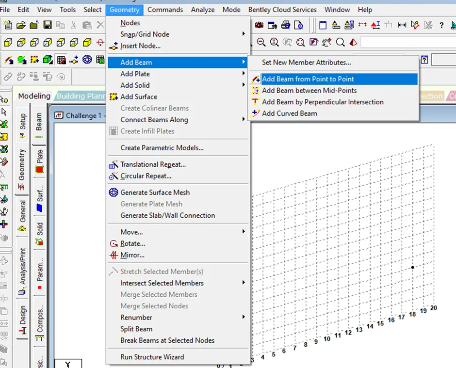
Go to Geometry tab and select add beam.
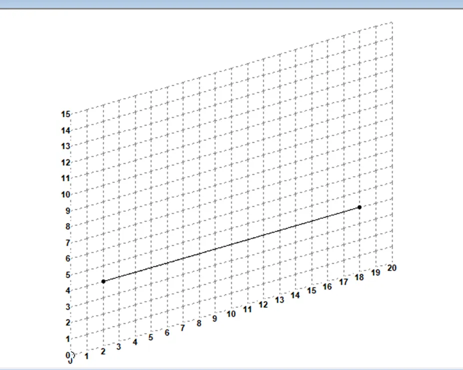
Now join the two nodes.
Adding supports to the beam
Select one node using node cursor.
Go to support page in the toolbar.
Supports dialog box appears.
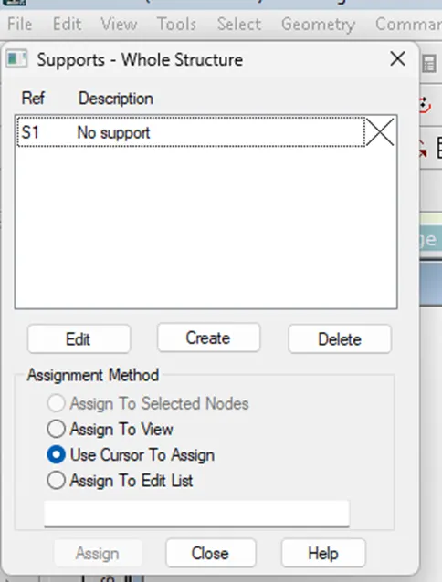
Click on Create option.
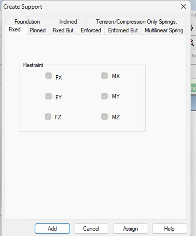
Select fixed condition and click on add.
Similarly select another node and add fixed but condition.
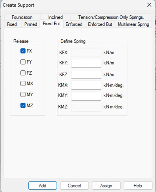
Click on add.
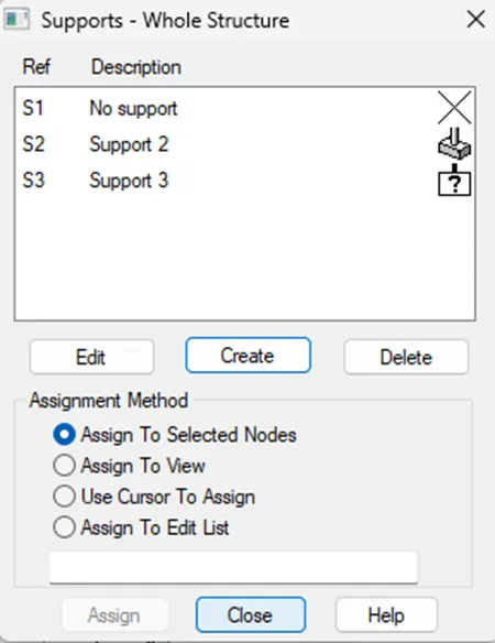
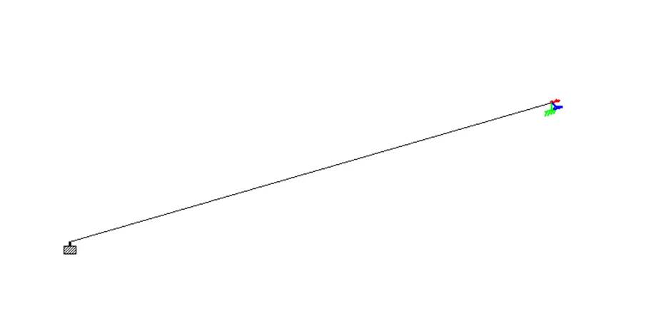
Choose the support created and Select assignment method and then select the node to assign.
Applying point load to the beam:
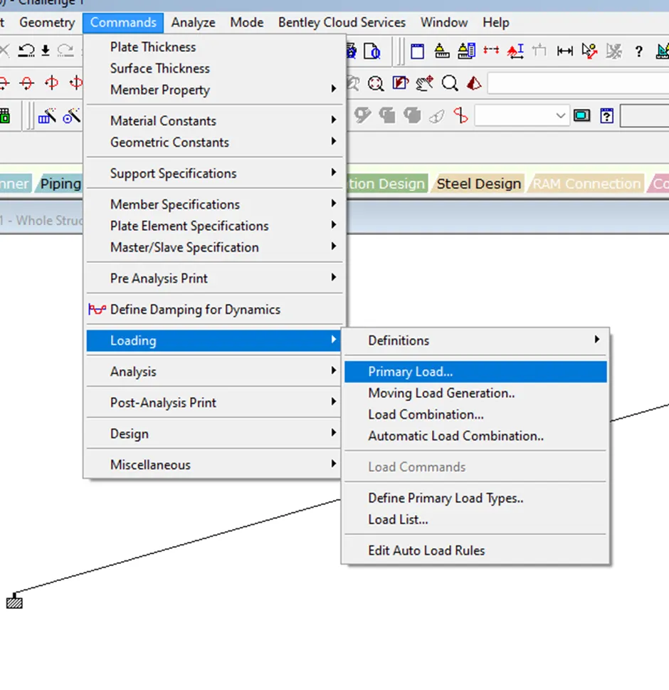
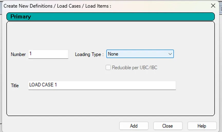
Select loading type as dead load. Add title if needed.
Click on Add and close.
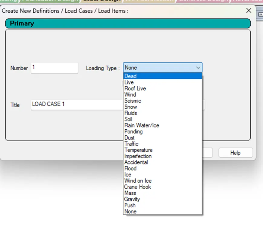
Select the dead load in load case details and then click on Add.
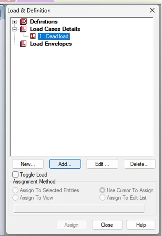
The following dialog box appears.
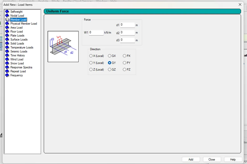
Select member load from the list.
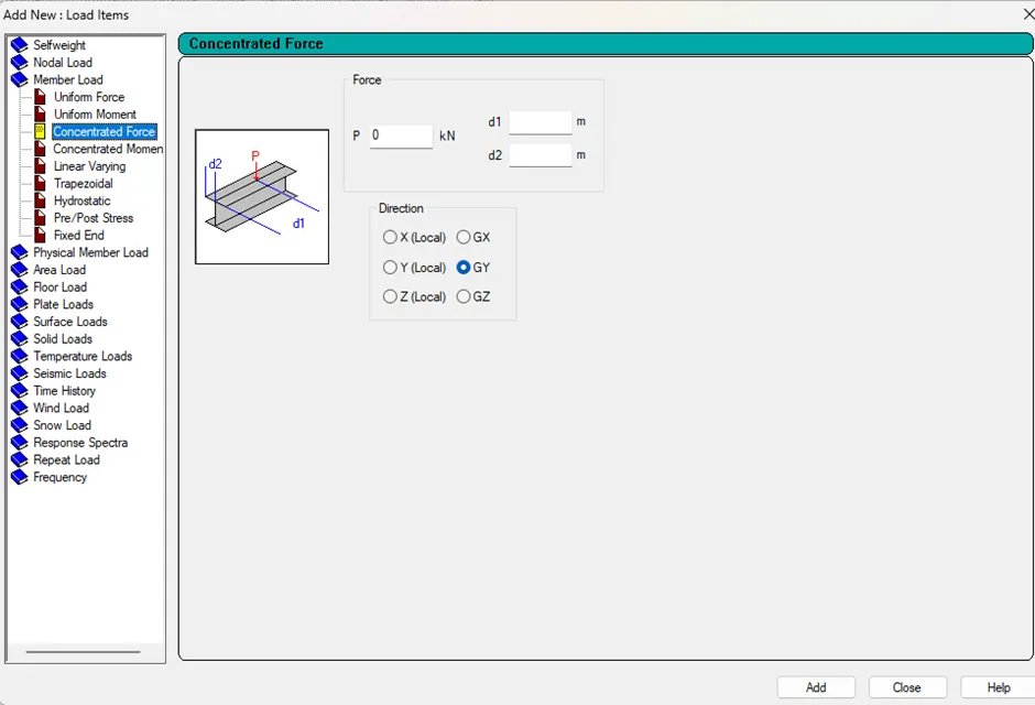
Select concentrated force and give the parameters for P, d1, and d2.
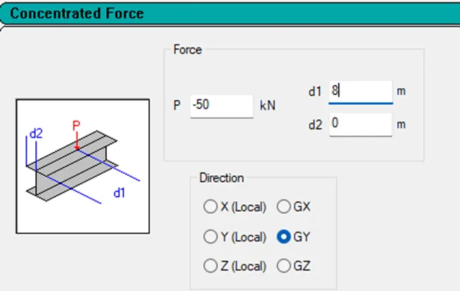
Click on Add and then Close.
Now select the load in load case details.
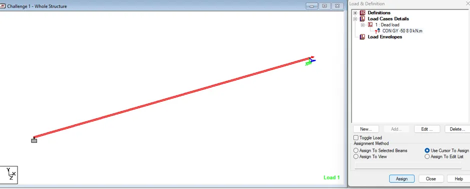
By using assignment method select the beam and then click on Assign.
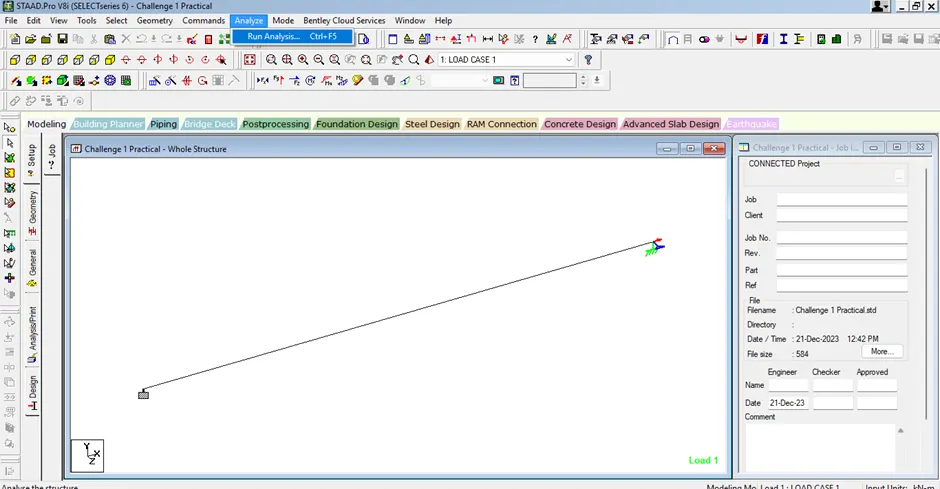
Now, go to Analyze tab and click on Run Analysis or press Ctrl+F5.
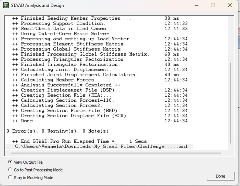
STAAD Analysis and Design window open. It shows the errors and warning if something is wrong.
Rectify the errors and perform the analysis again.
Drawing SFD and BMD:
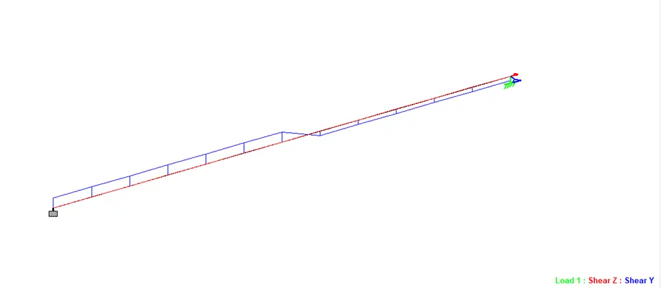
Click on analysis results to view shear force, bending moment and displacement diagrams.

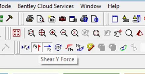
Shear force diagram:
Click on shear force icon.
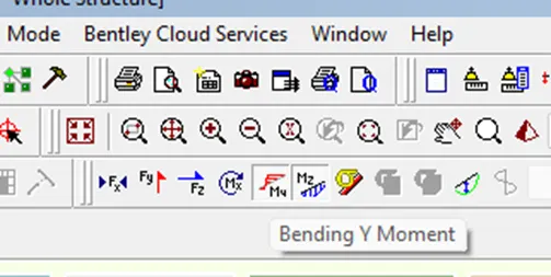
Bending moment diagram:
Click on the bending moment icon.
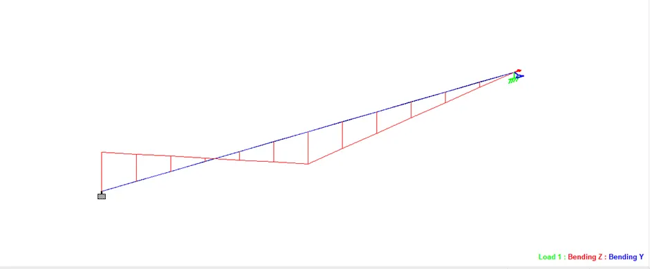
Result: STAAD model is created with the given specifications.