Creating Conceptual mass in REVIT and Creation of Sinusoidal curve and a Parametric stadium using Dynamo
1. Answer:
Aim: To create a set of sinusoidal points and to create a curve and to create a surface out of the curve by using Dynamo.
Introduction:
Dynamo is an open source visual programming platform for designing. It is installed as part of Revit along with Revit specific programming nodes. Revit Dynamo allows to type lines of code as well as an algorithm that consists of nodes. It has several advantages that helps improvise the project design process and its operations. The software has an intuitive interface and many premade scripting libraries available as well.
The simplest geometrical object in the Dynamo standard library is a point. All geometry is created using special functions called constructors, which each return a new instance of that particular geometry type. In Dynamo, constructors begin with the name of the object’s type, in this case Point, followed by the method of construction.
To create a three-dimensional point specified by x, y, and z Cartesian coordinate, use the ByCoordinates constructor.
Points can be used to construct higher dimensional geometry such as lines. We can use the ByStartPointEndPoint constructor to create a Line object between two points.
Similarly, lines can be used to create higher dimensional surface geometry.
Loft constructor: which takes a series of lines or curves and interpolates a surface between them.
Tools used:
Integer Slider - Produces integer value.
Range - Creates a sequence of numbers or letters in the given range.
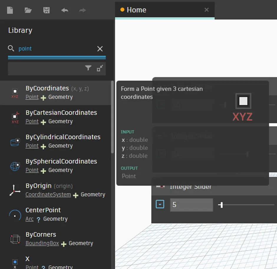
Point.Bycoordinates – Form a Point given 3 cartesian coordinates.
Code Block – Allows for DesignScript code to be authored directly.
Math.Sin – Finds the sine of an angle.
Product – Returns multiplication of x times y.
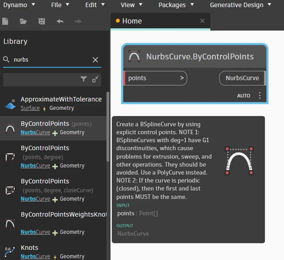
Nurbscurve.ByControlPoints – Create a Spline Curve by using explicit control points.
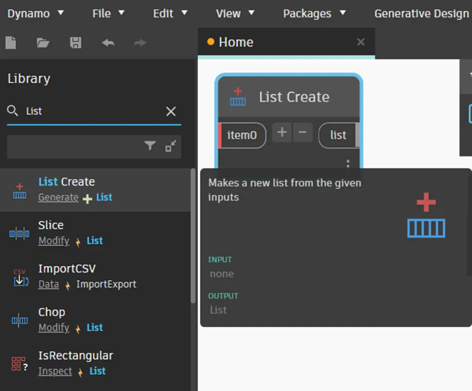
List Create – Makes a new list from the given inputs.
Surface.ByLoft – Create a Surface by lofting between input cross section Curves.
Procedure:
Open New Architectural template in Revit.
Click Manage tab > Visual Programming Panel > Dynamo.
Creating points in Dynamo:
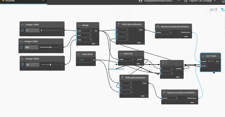
In search tab, type ‘Integer Slider’.
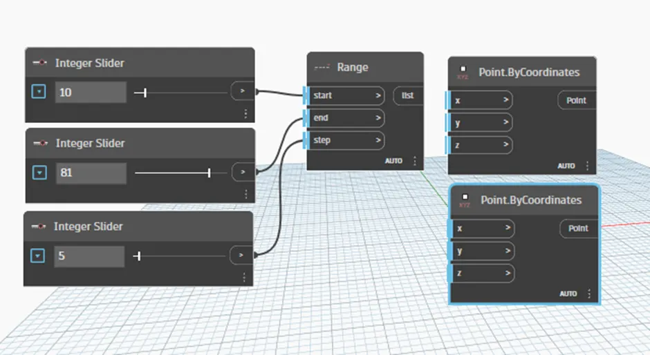
Insert 3 ‘Integer Slider’ in workspace.
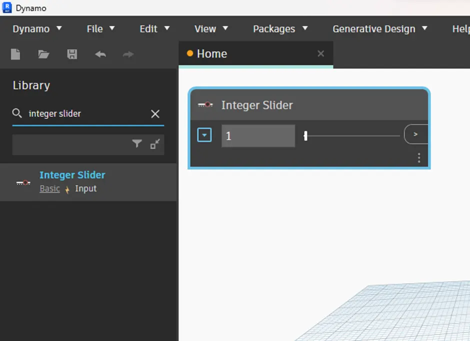
Add minimum and maximum values and then adjust the sliders to the required value.
Search for ‘Range’ node in library and insert in workspace.
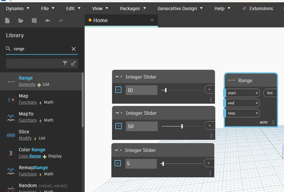
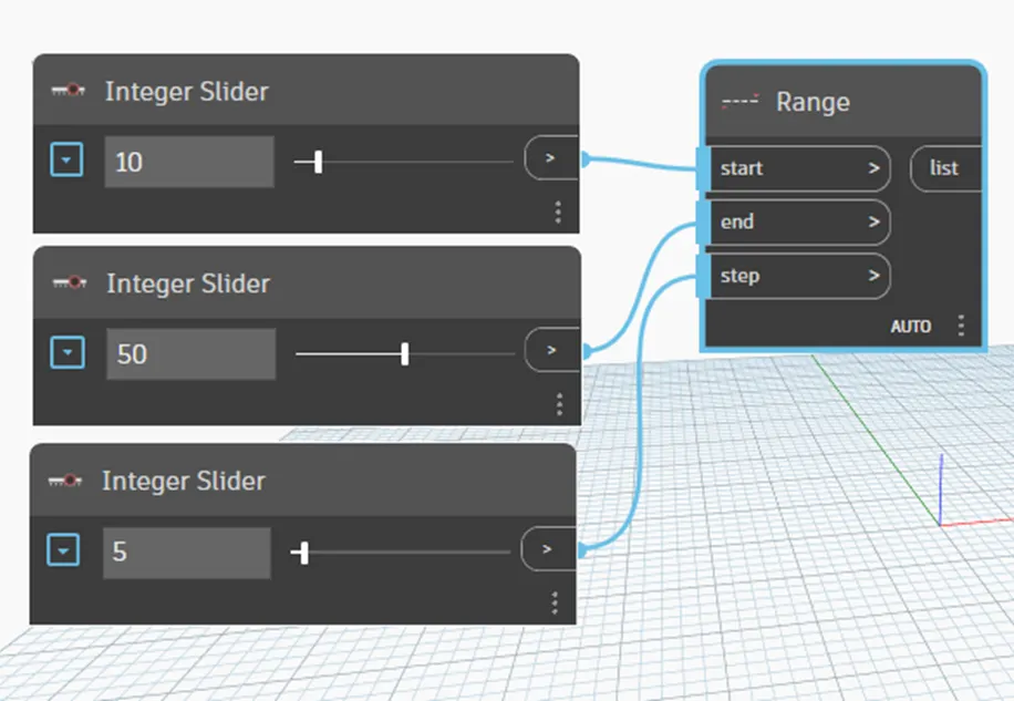
Connect each ‘Integer Slider’ to start, end and step in the range.
Search for ‘Point.Bycoordinates’ node in library, insert 2 nodes in workspace.
Search for ‘Code Block’ tool, and insert it in workspace.
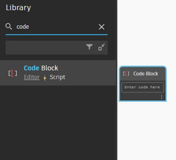
Add value to the Code Block.
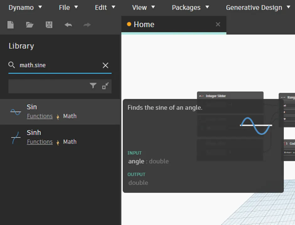
Search for ‘Math.Sin’ node in library and insert the node in workspace.
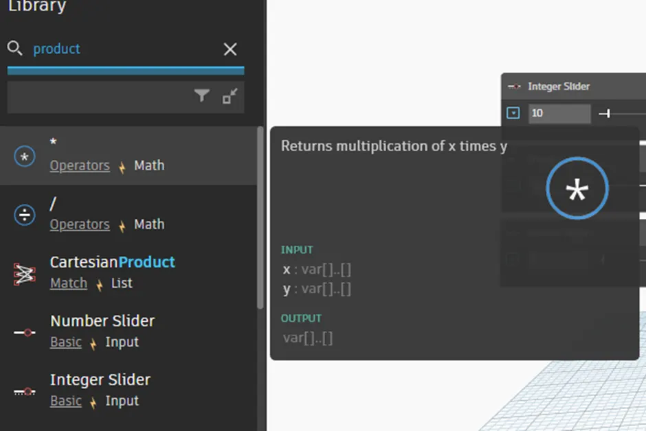
Insert ‘Product’ node in workspace.
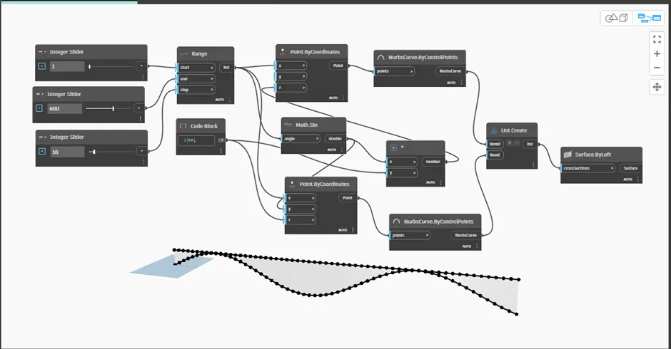
Connect the output of 'Range' to the first x coordinate, to ‘Math.Sin’ angle and to the second x coordinate separately.
Connect ‘Math.Sin’ output to second y coordinate and ‘Code Block’ to second z coordinate. Connect ‘Math.Sin’ output to x of ‘Product’, and ‘Code Block’ to y of ‘Product’.
Connect the ‘Product’ output to first z coordinate.
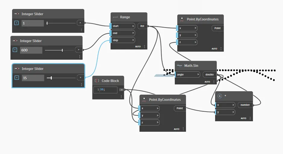
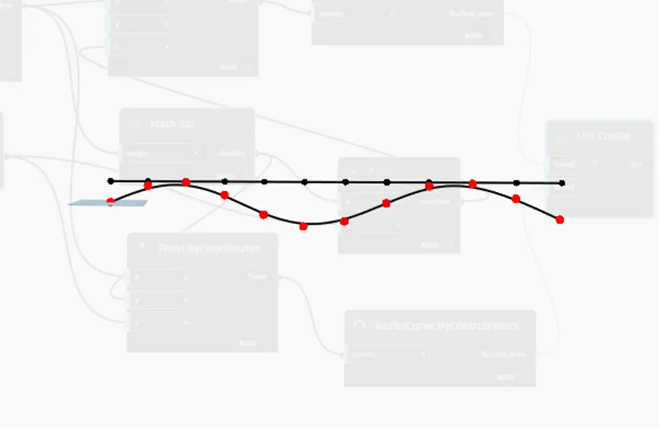
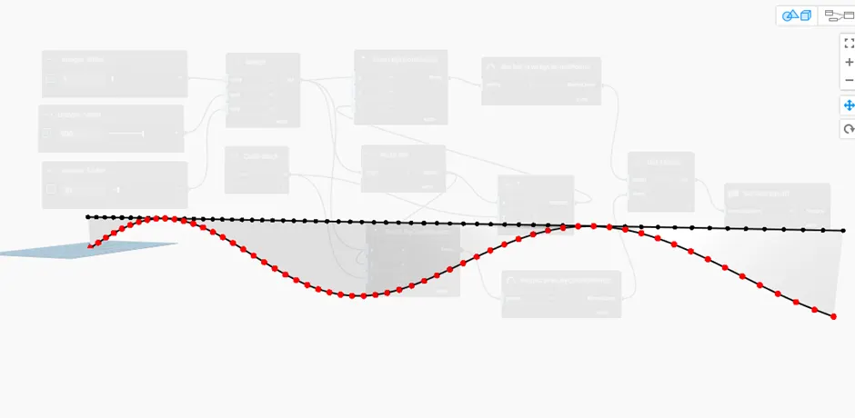
Sinusoidal points are created.
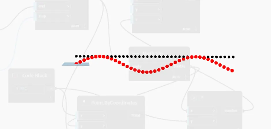
Creating curve in Dynamo:
Search for ‘Nurbscurve.ByControlPoints’vin library and insert 2 nodes in workspace.
Search for ‘List Create’ node in library and insert it in workspace.
Connect output of first ‘Point.ByCoordinates’ to points in first ‘Nurbscurve.ByControlPoints’ and output of second ‘Point.ByCoordinates’ to points in the second ‘Nurbscurve.ByControlPoints’
Now add items to the ‘List Create’ by clicking on addition symbol and then connect outputs of first and second ‘NurbsCurve.ByControlPoints’ to the item0 and item1 in the list respectively.
Curve is created by joining the points.
Creating Surface in Dynamo:
Search for ‘Surface.ByLoft’ node in library and insert it in workspace.
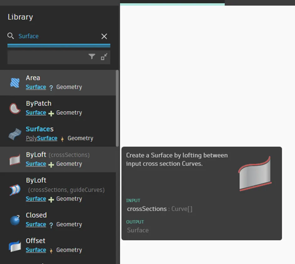
Connect output of ‘List Create’ to the cross-sections of ‘Surface.ByLoft’.
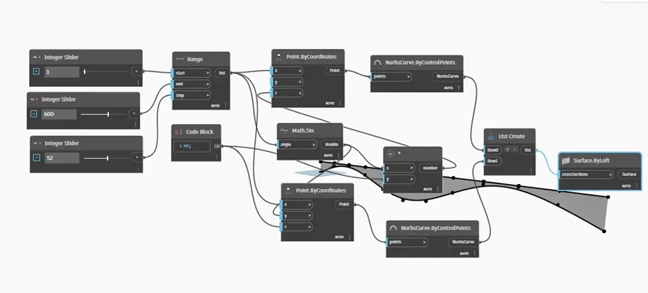
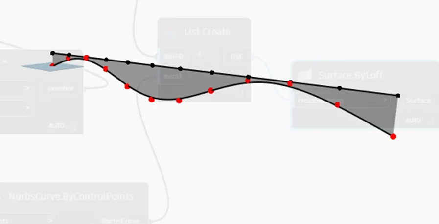
The surface is created.
Result:
Sinusoidal points, curve and surface are created in Dynamo.
2. Answer:
Aim: To create a conceptual layout of floor plan in Dynamo. Using the tools available in dynamo for linking the lines to appropriate model elements in Revit by choosing the wall types and wall parameters. Using the sliders to slide through the height of the wall and length of the wall.
Tools used:
Integer Slider - Produces integer value.
Point.ByCoordinates - Form a Point given 3 cartesian coordinates.
Line.ByStartPointEndPoint – Creates a straight line between two input points.
List Create - Makes a new list from the given inputs.
Levels – Select a level in the active document.
Wall Types – All wall types available in the document.
WalByCurveAndHeight – Create a Revit Wall from a guiding Curve, Height, Level and Wall type.
Floor.ByOutlineTypeAndLevel – Create a Revit Floor given its curve outline and Level.
Floor Types – All floor types available in the document.
Procedure:
Open New Architectural template in Revit.
Click Manage tab > Visual Programming Panel > Dynamo.
Search for ‘Integer Slider’ in library, insert 2 ‘Integer Slider’ in workspace.
Add minimum and maximum values and adjust the value by using slider.
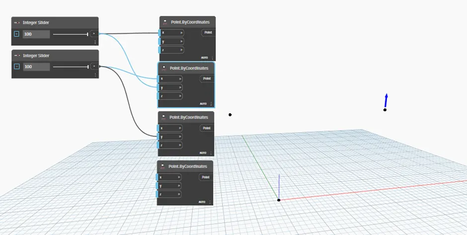
Search for ‘Point.ByCoordinates’ node in library, and insert 4 nodes in workspace.
Connect first ‘Integer Slider’ to first x coordinate, first ‘Integer Slider’ to the second y coordinate.
Connect second ‘Integer Slider’ to second x coordinate, second ‘Integer Slider’ to the third y coordinate.
Search for ‘Line.ByStartPointEndPoint’ node in library, insert 4 nodes in workspace.
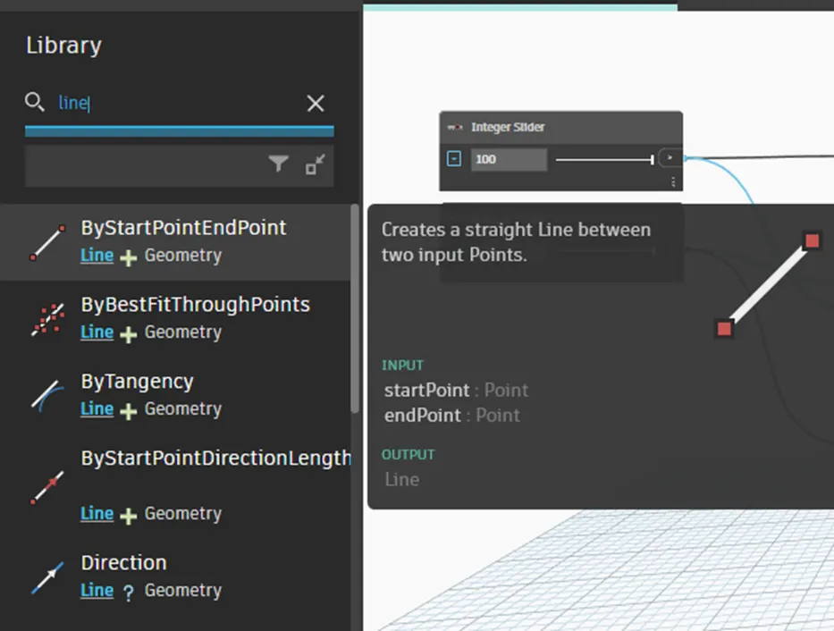
Now, connect first ‘Point.ByCoordinate’ to the startPoint of first ‘Line.ByStartPointEndPoint’ and to the end point of fourth ‘Line.ByStartPointEndPoint’.
Connect second ‘Point.ByCoordinate’ to the end point of first ‘Line.ByStartPointEndPoint’ and to the start point of second ‘Line.ByStartPointEndPoint’.
Connect third ‘Point.ByCoordinate’ to the end point of second ‘Line.ByStartPointEndPoint’ and to the start point of third ‘Line.ByStartPointEndPoint’.
Connect fourth ‘Point.ByCoordinate’ to the end point of third ‘Line.ByStartPointEndPoint’ and to the start point of fourth ‘Line.ByStartPointEndPoint’.
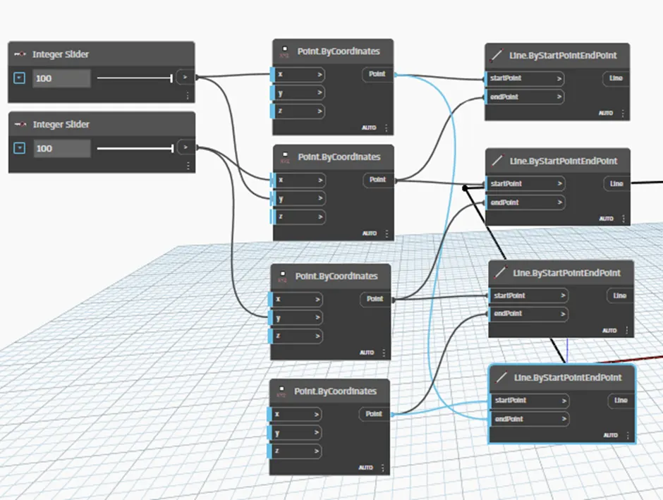
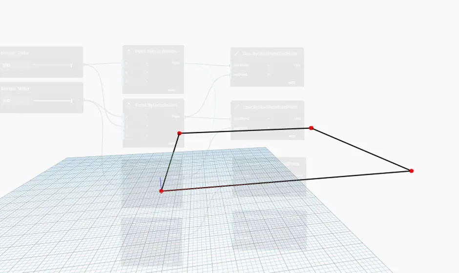
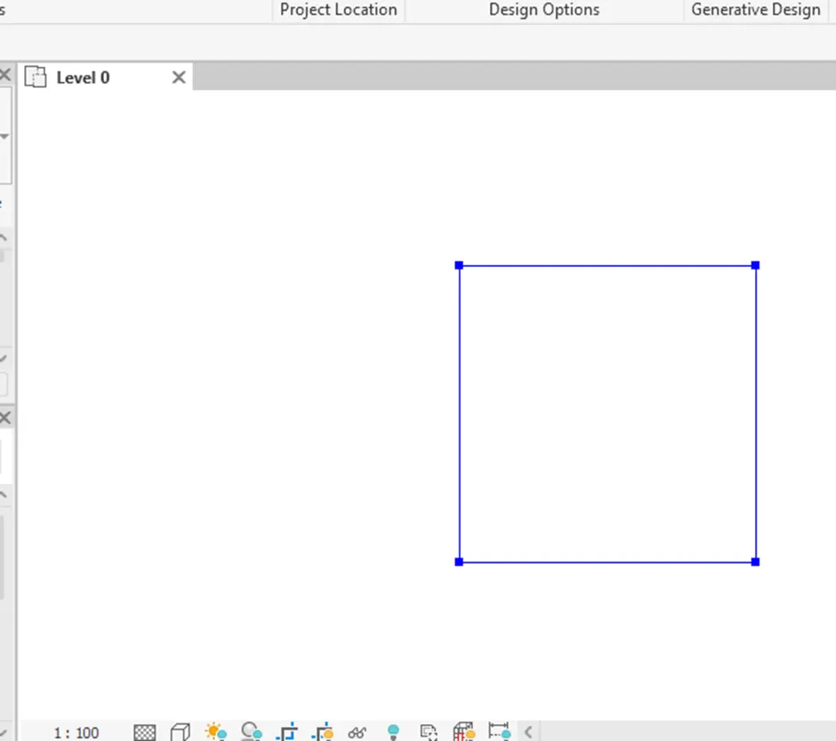
Search and insert ‘List Create’. Add 3 items to the list by clicking on addition symbol.
Connect outputs of 4 ‘Line.ByStartPointEndPoint’ to each item in the list.
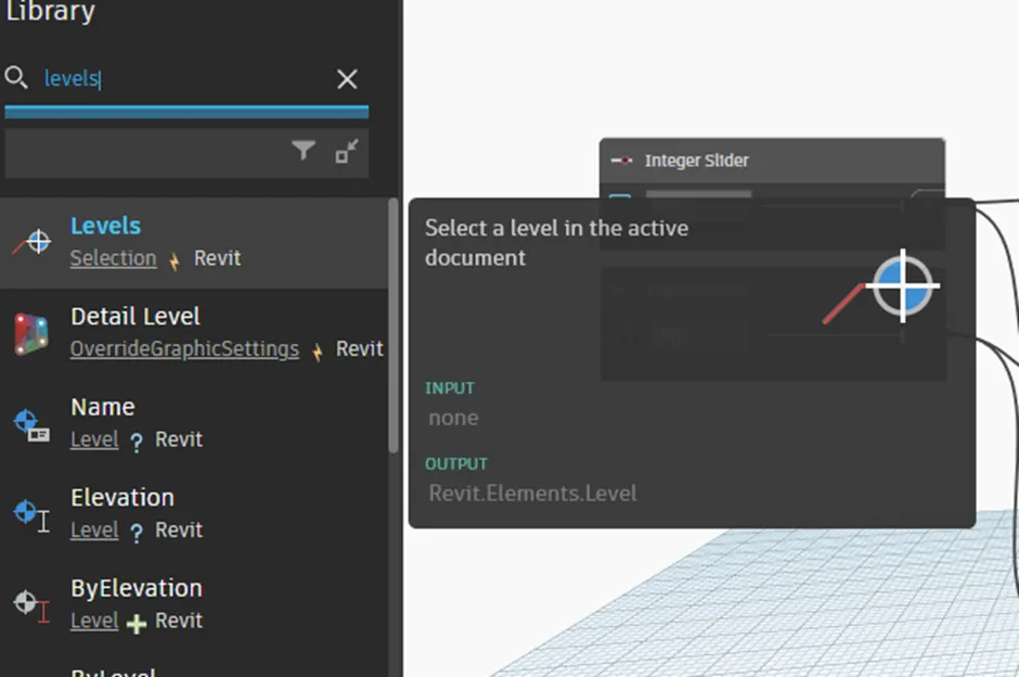
Search for ‘Levels’ in library, and insert in workspace.
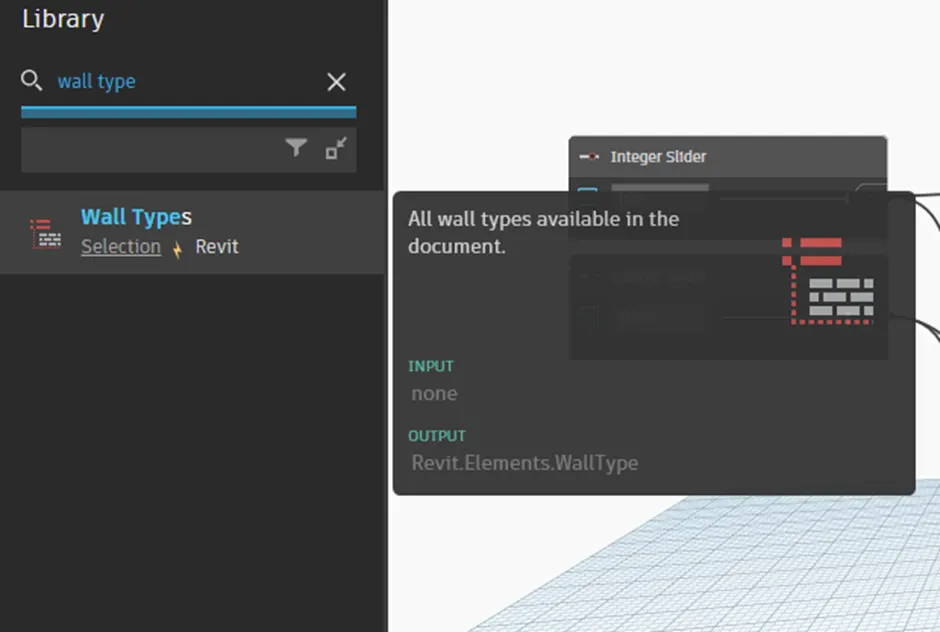
Search ‘Wall Types’ in library, insert in workspace.
Insert one ‘Integer Slider’.
Add minimum and maximum value and adjust the integer slider.
Choose level in ‘Levels’ and wall type in ‘Wall Types’.
Search ‘Wall.ByCurveAndHeight’ node in library, and insert it in workspace.
I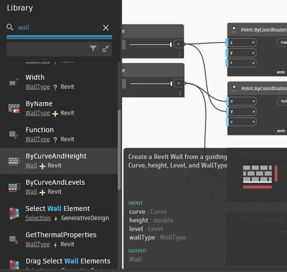
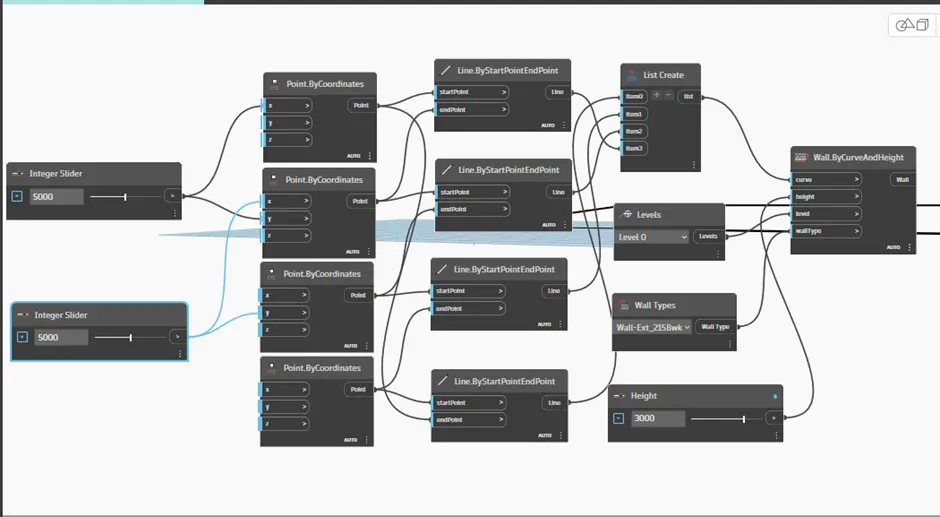
Now, connect output of ‘List Create’ to curve, ‘Integer Slider’ to height, levels to level and ‘Wall Types’ to wall type in ‘Wall.ByCurveAndHeight’.
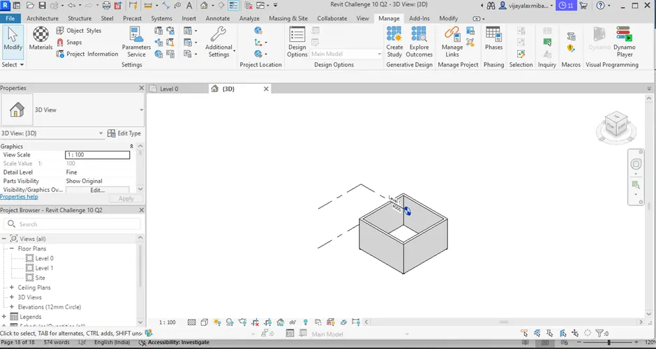
Search for ‘Floor.ByOutlineTypeAndLevel’ node in library, insert the node in workspace.
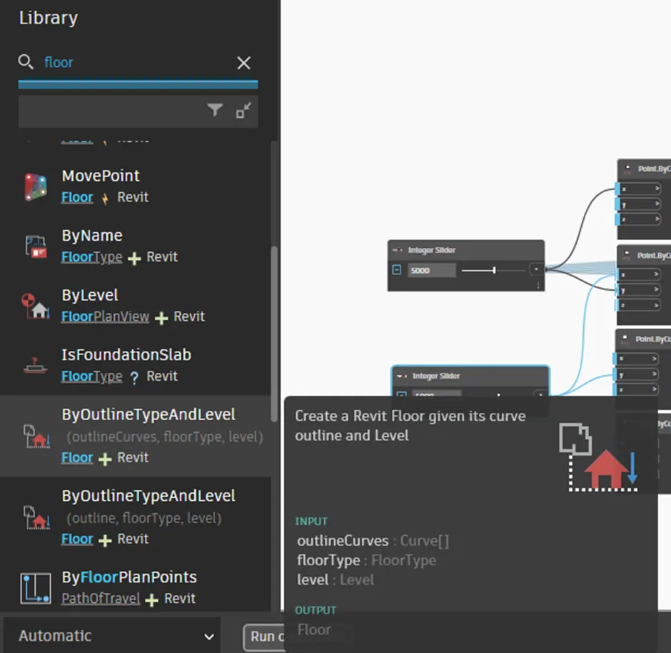
Search for ‘Floor types’ in library, insert it in workspace. Choose floor type.
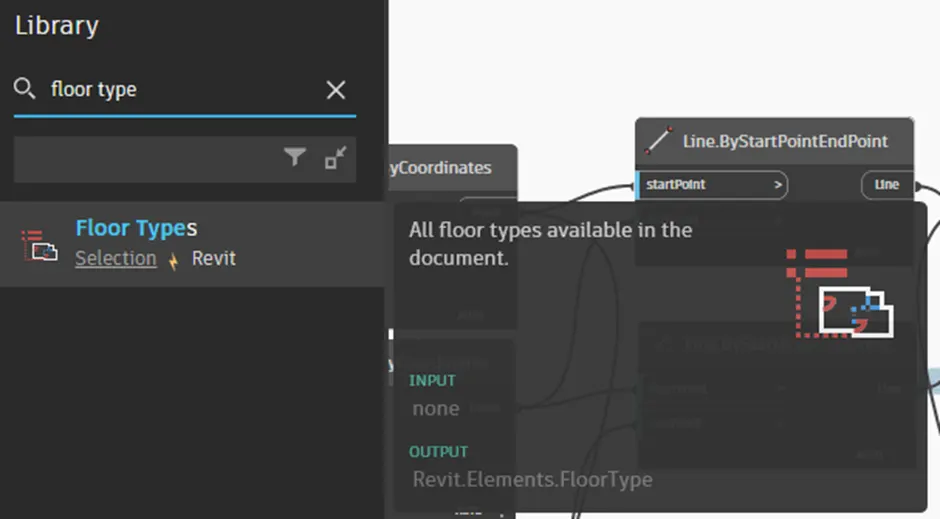
Connect output of ‘List Create’ to outlineCurves, ‘Floor type’ to floor type and ‘Levels’ to level in ‘Floor.ByOutlineTypeAndLevel’.
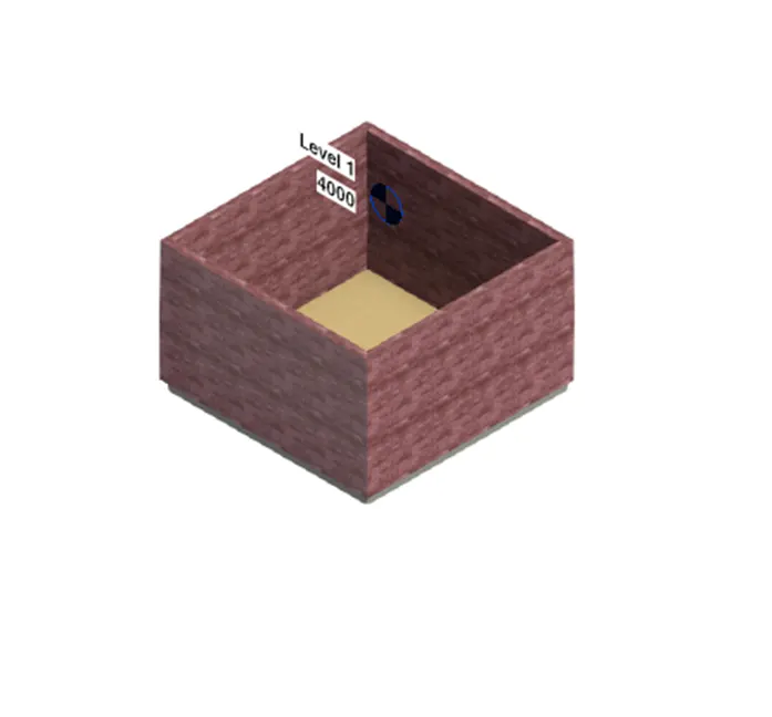
Floor is created using Dynamo.
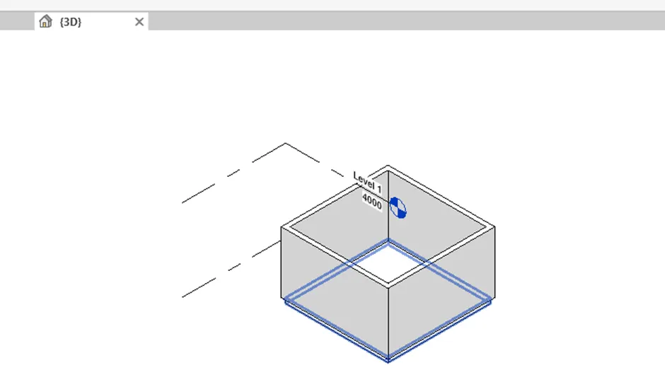
Result: Conceptual layout of floor plan is created in Dynamo. Tools available in dynamo are used for linking the lines to appropriate model elements in Revit by choosing the wall types and wall parameters. Sliders are used to slide through the height of the wall and length of the wall.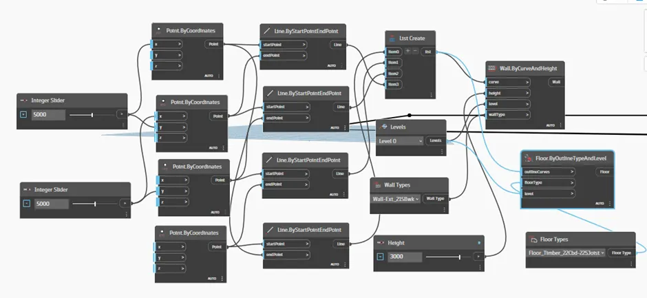
3. Answer:
Aim: To create an array of model elements in Revit and to use dynamo to vary the properties of model elements by using the slider or code block.
Tools used:
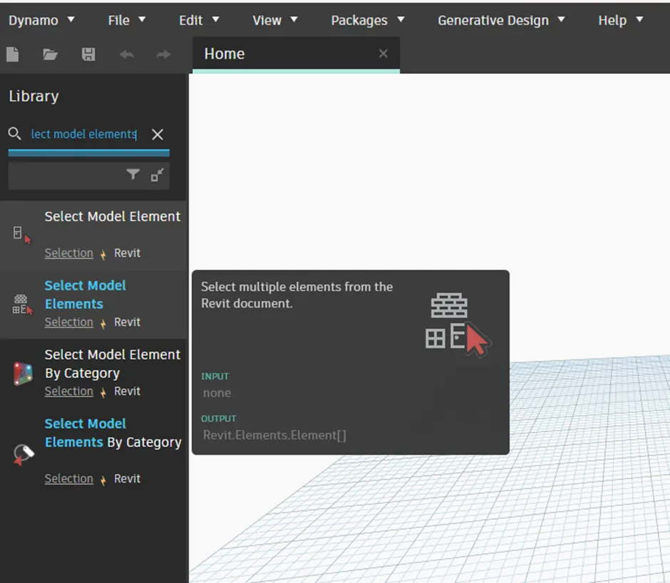
Select Model Elements – Select multiple elements from the Revit document.
Integer Slider - Produces integer value.
FamilyInstance.SetRotation - Rotates an object around an origin and an axis by a specified degree.
Procedure:
Open Revit software.Create new architectural template.
Go to Architecture tab and select architectural column.
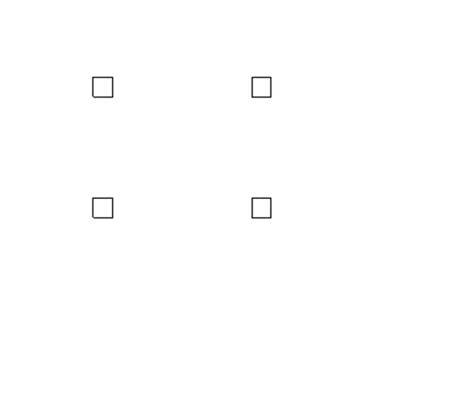
Place a column in the model. Using Array tool place 3 more columns.
Click Manage tab > Visual Programming Panel > Dynamo.
Open new file in dynamo.
Search for ‘Select Model Elements’ tool and insert it in workspace.
Go to Revit and select previously created columns.
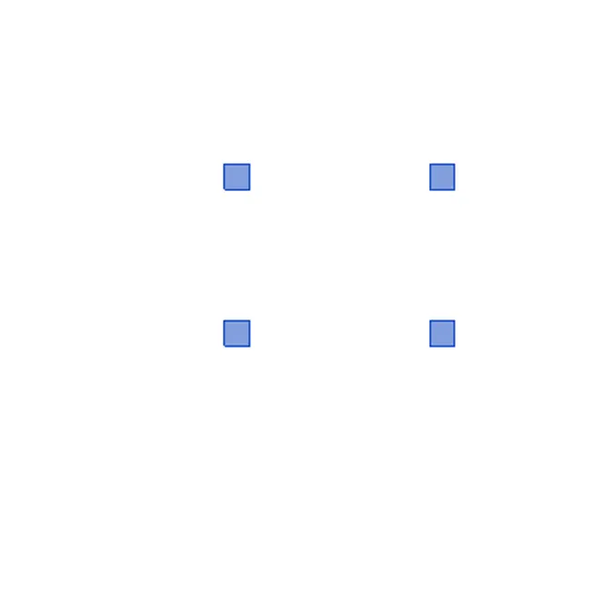
Model elements are selected.
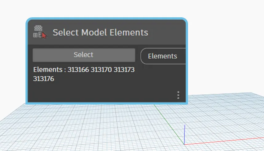
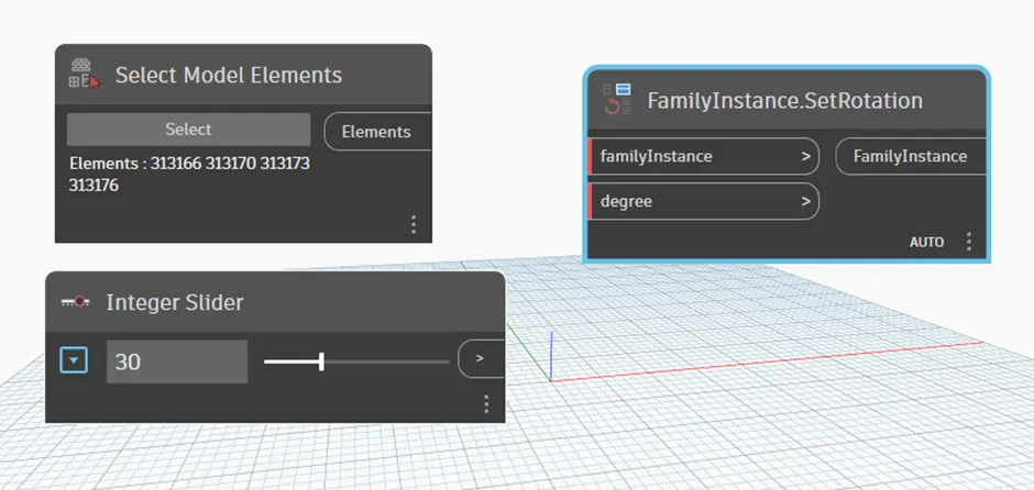
Search for ‘Integer Slider’, insert it in workspace. Add minimum and maximum values and adjust the slider (Here value represents angle).
Search for ‘FamilyInstance.SetRotation’ node, insert the node in workspace.
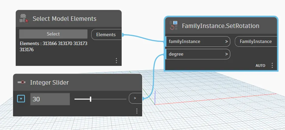
Now, connect ‘Select Model Elements’ to familyInstance and ‘Integer Slider’ to degree in ‘FamilyInstance.SetRotation’.
Open the Revit file in background, check whether selected elements are rotated or not.
Result: An array of model elements are created in Revit and dynamo is used to vary the properties of model elements by using the slider or code block.
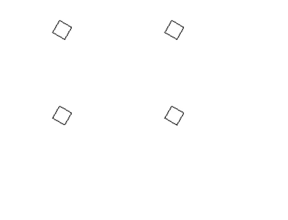
Elements are rotated in 30 degrees.
4. Answer:
Aim: To create a conceptual mass in Revit and develop a parametric column by dividing the surfaces and apply the concepts similar to use in parametric walkway modelling. To use triangular bent or square shaped panels to add finish to the parametric column.
Procedure:
Open a new architectural template in Revit.
Go to File tab and choose New option, then select Conceptual Mass.
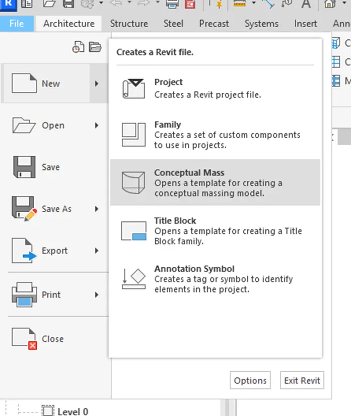
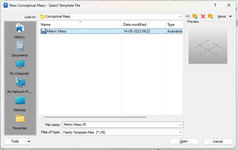
Choose 'Metric mass' option and click on open.
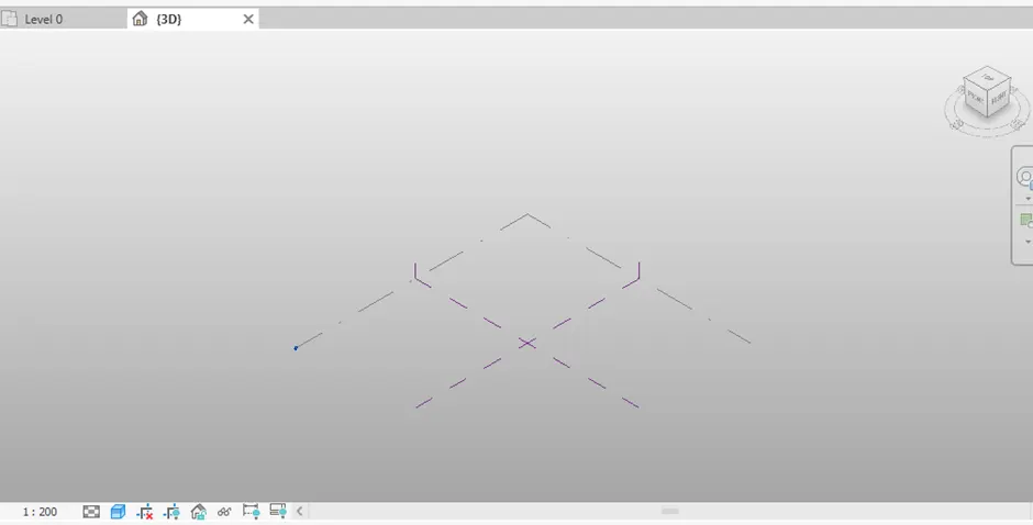
Open Elevation view and create level.
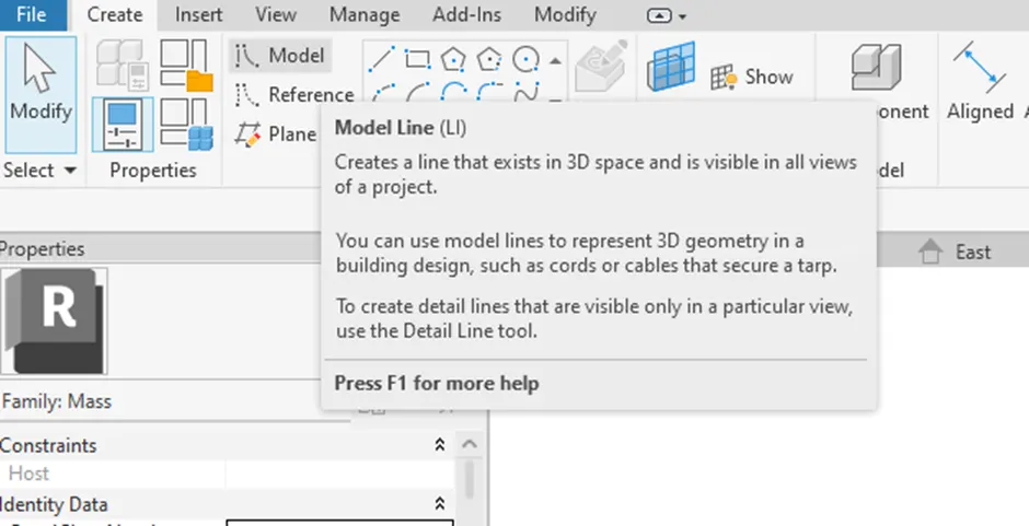
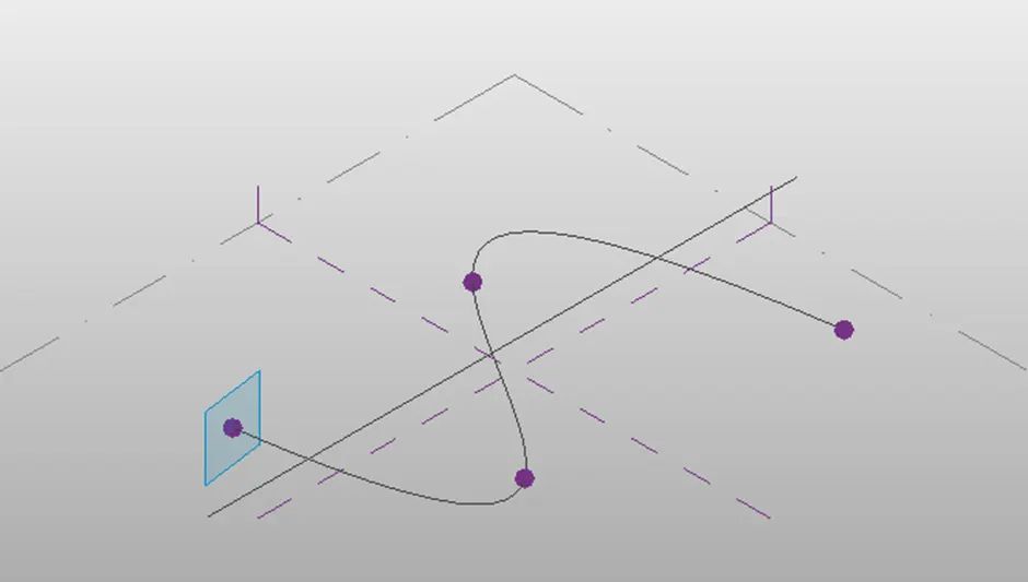
Open Floor Plan, go to ‘Create’ tab and choose ‘Model Line’ tool.
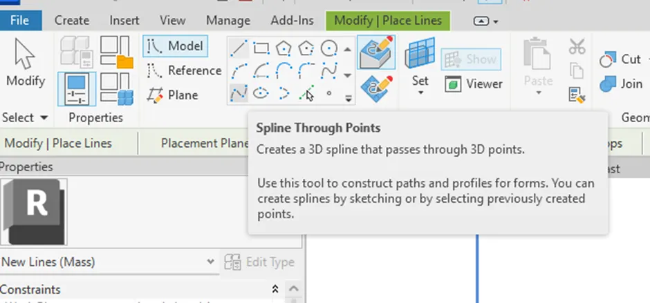
Now, choose ‘Spline Through Points’ option.
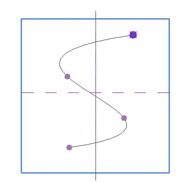
Create curve by placing points.
Open 3D View.
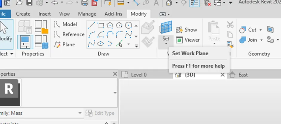
By using Set work plane tool in Modify tab create plane at every point.
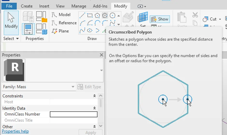
Use circumscribed polygon tool in modify tab and create polygon at each plane.
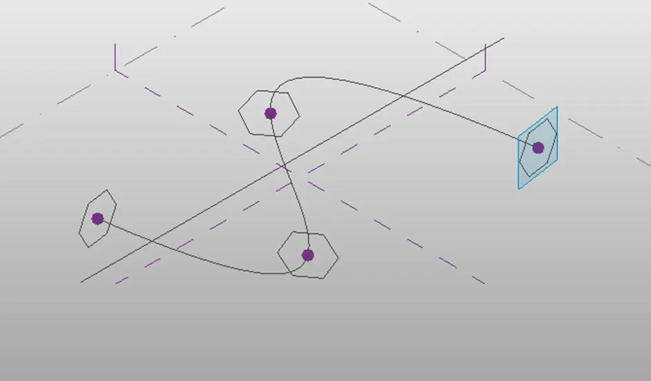
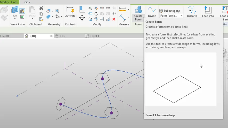
Now, select the curve and polygons.
In Ribbon tab, select the ‘Create Form’ option.
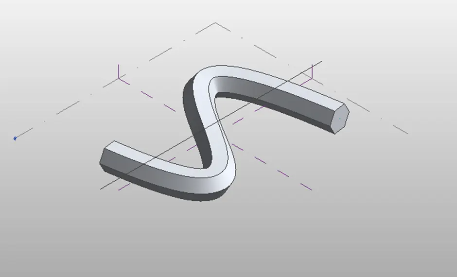
Now, select the created solid.
Choose filter option from the ribbon tab.

Choose form option and click on OK.
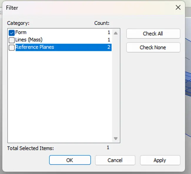
Now select all and then choose 'Divide Surface' option.
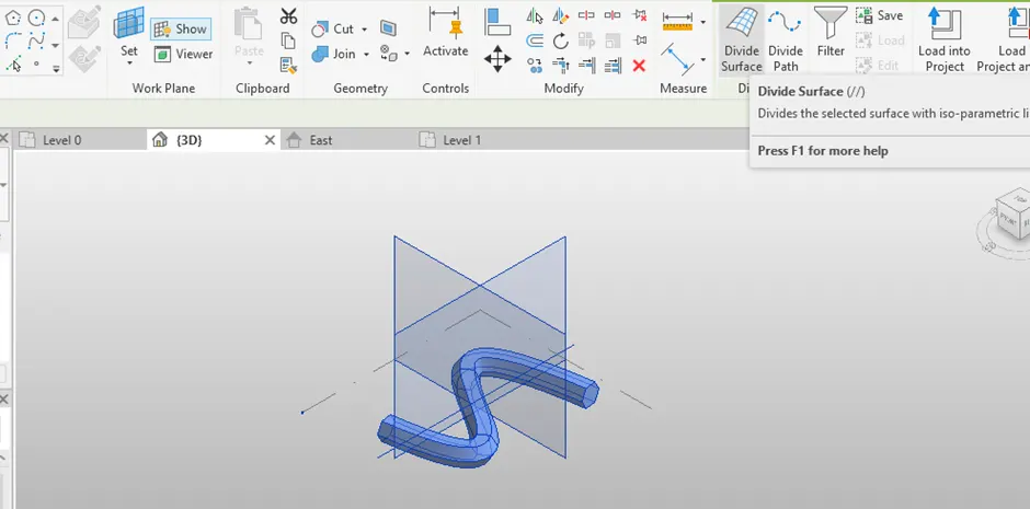
Now, choose 'Triangular (bent)' option in property browser.
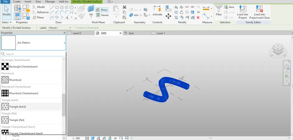
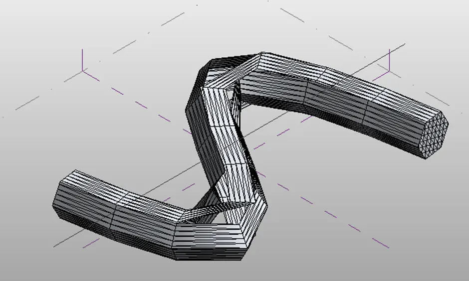
Triangular bent is applied to the solid.
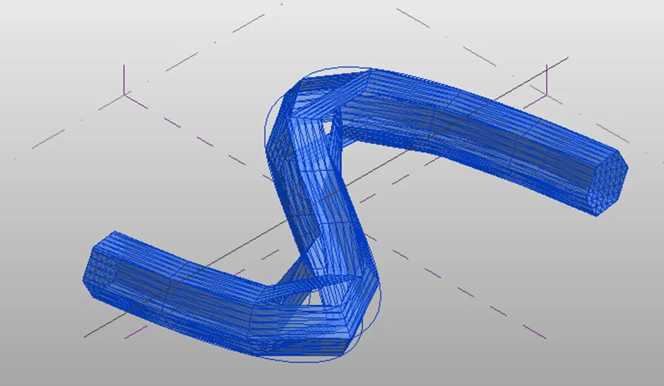
Result: A conceptual mass is created in Revit and developed a parametric column by dividing the surfaces and applied the concepts similar to use in parametric walkway modelling. Triangular bent panels are added to the parametric column.
5. Answer:
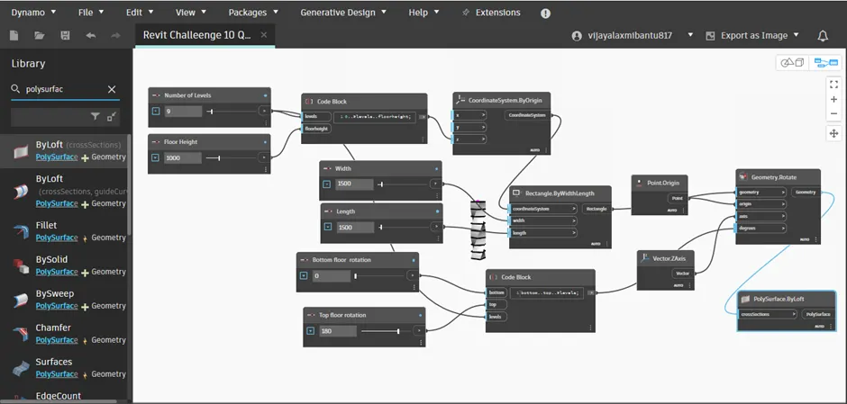
Aim: To use Dynamo for developing a Parametric Stadium and to list the parameters and to use the visual programming approach to complete the modelling.
Tools used:
Integer Slider - Produces integer value.
Code Block - Allows for DesignScript code to be authored directly.
CoordinateSystem.ByOrigin - Creates a Poimt representing the CoordinateSystem origin.
RectangleByWidthLength - Create a Rectangle centered at the input origin in the CoordinateSystem XY Plane, with specified width and length.
Point.Origin - Get the Origin point (0,0,0).
Vector.ZAxis - Get the canonical Z axis Vector (0,0,1)
Geometry.Rotate - Rotates an object around an origin and an axis by a specified degree.
PolySurface.ByLoft - Makes PolySurface by Loft through Curves.
Procedure:
Open New Architectural template in Revit.
Click Manage tab > Visual Programming Panel > Dynamo.
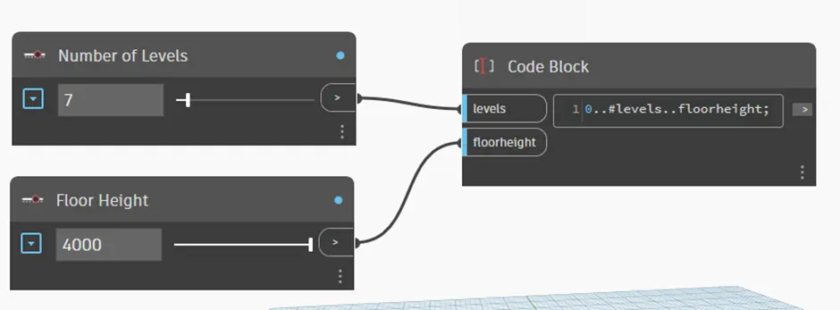
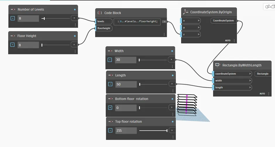
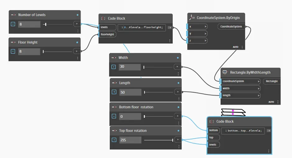
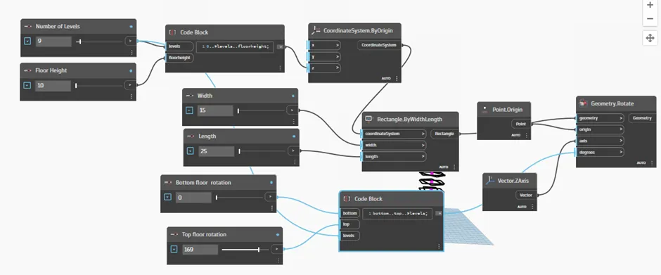
Search for ‘Integer Slider’ in library, and insert two two nodes in workspace. Rename them as ‘Number of Levels’ and ‘Floor Height’.
Search for ‘Code Block’ in library, insert it in Dynamo.
Connect ‘Number of Levels’ to levels and ‘Floor Heigh’t to floorheight in ‘Code Block’.
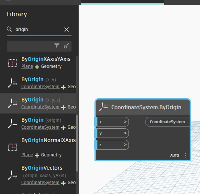
Search for ‘CoordinateSystem.ByOrigin’ node in library, insert it in workspace.
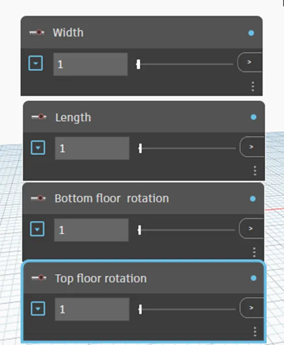
Search and insert four ‘Integer Slider’ in workspace.
Rename them as Width, Length, Bottom floor rotation and top floor rotation.
Add minimum and maximum values and adjust sliders to give value for the parameter by sliding.
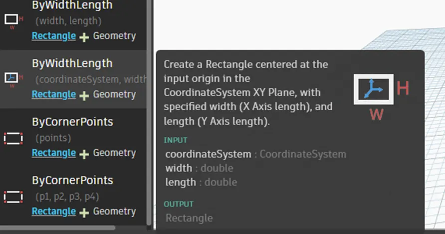
Search for ‘RectangleByWidthLength’ node in library, insert it in workspace.
Now, connect ‘Code block’ to the z coordinate of ‘CoordinateSystemByOrigin’.
Connect output of ‘CoordinateSystemByOrigin’ to coordinateSystem , ‘Width’ to width and ‘Length’ to length of ‘Rectangle.ByWidthAndLength’.
Search ‘Code Block’, insert it in workspace.
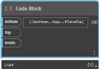
Connect ‘Bottom floor rotation’ to bottom, ‘Top floor rotation’ to top and ‘Number of Levels’ to levels in ‘Code Block’.
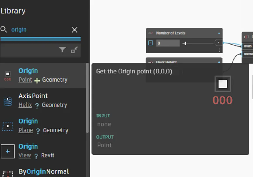
Search for ‘Point.Origin’ node in library, insert it in workspace.
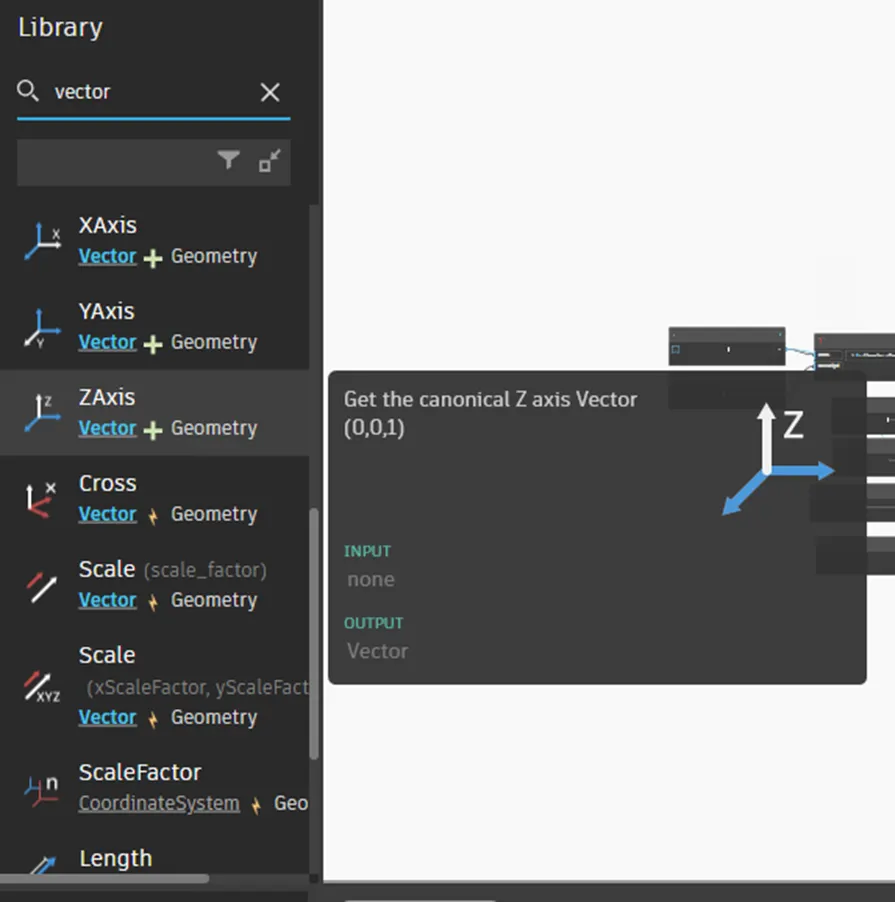
Search for ‘Vector.ZAxis’ in library, insert it in workspace.
Search for ‘Geometry.Rotate’ tool in library, insert it in workspace.
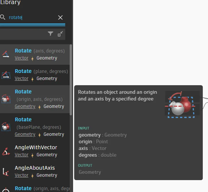
Connect output of ‘Rectangle.ByWidthLength’ to geometry, ‘Point.Origin’ to origin, ‘Vector.ZAxis’ to axis and ‘Code Block’ to degrees in ‘Geometry.Rotate’.
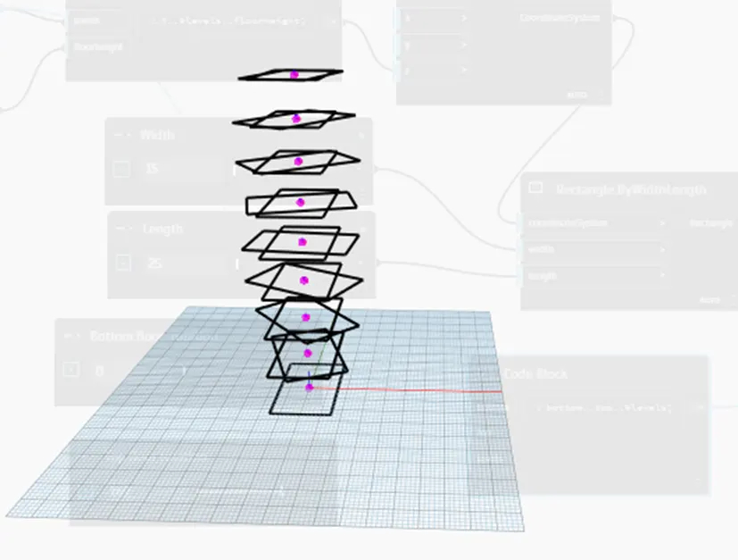
Search for ‘PolySurface.ByLoft’ node in library, insert it in workspace.
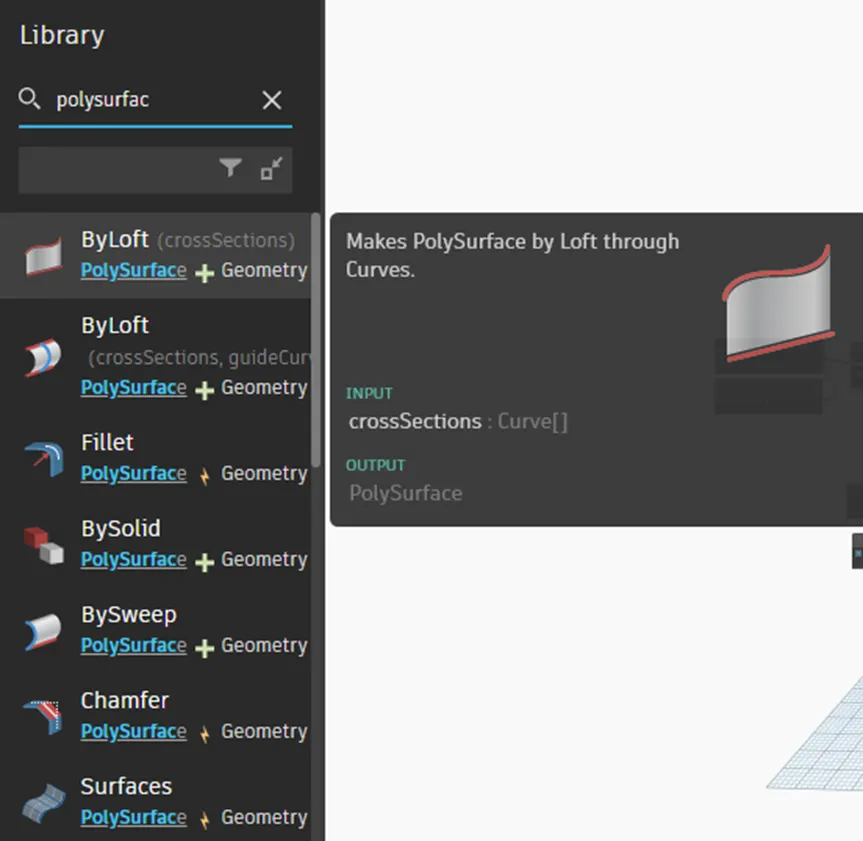
Connect output of ‘Geometry.Rotate’ to crossSection of ‘Polysurface.ByLoft’.
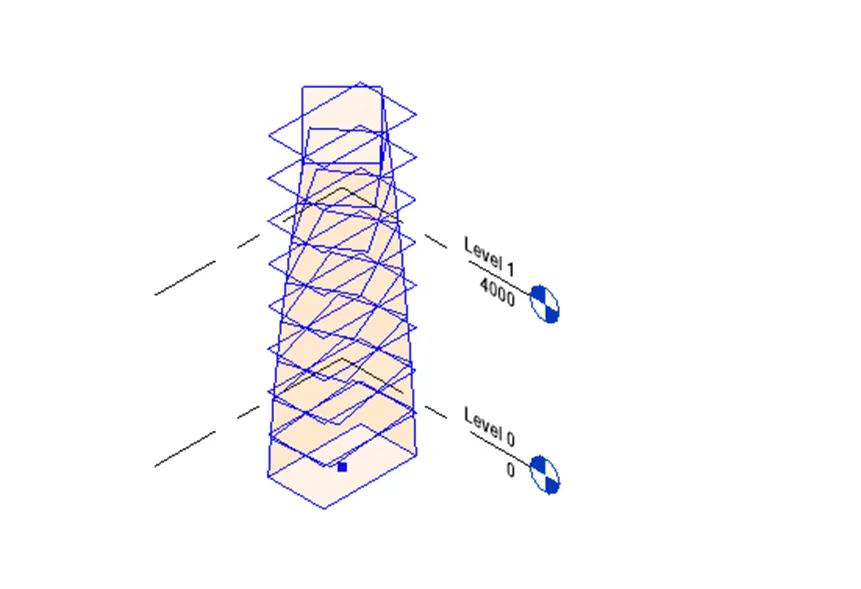
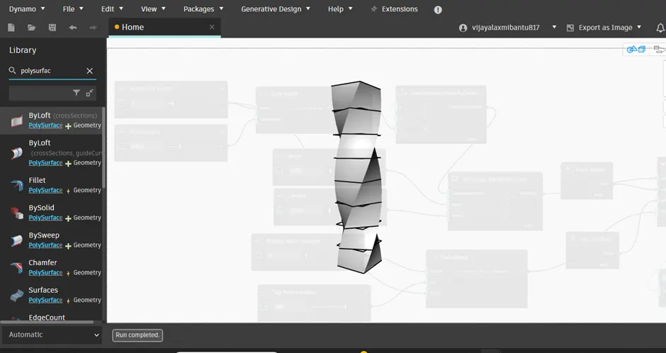
When angle is 45 degrees:
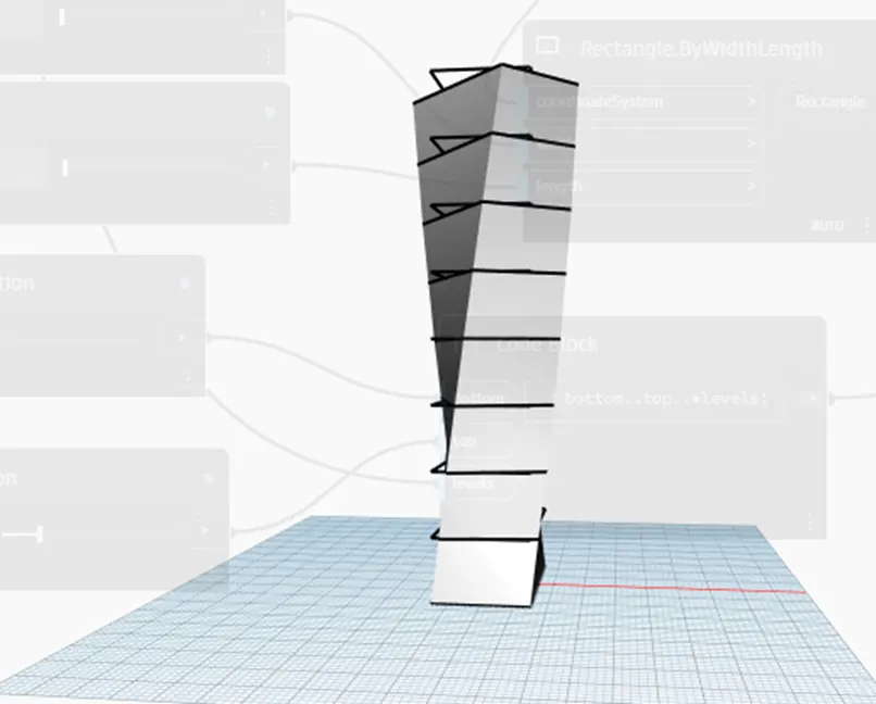
When angle is 90 degrees:
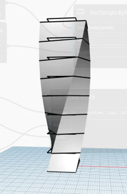
When angle is 180 degrees:
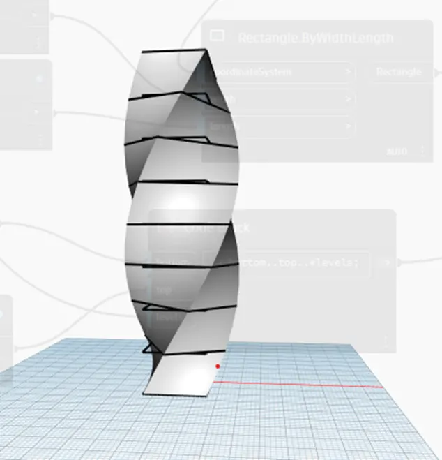
When angle is 240 degrees:
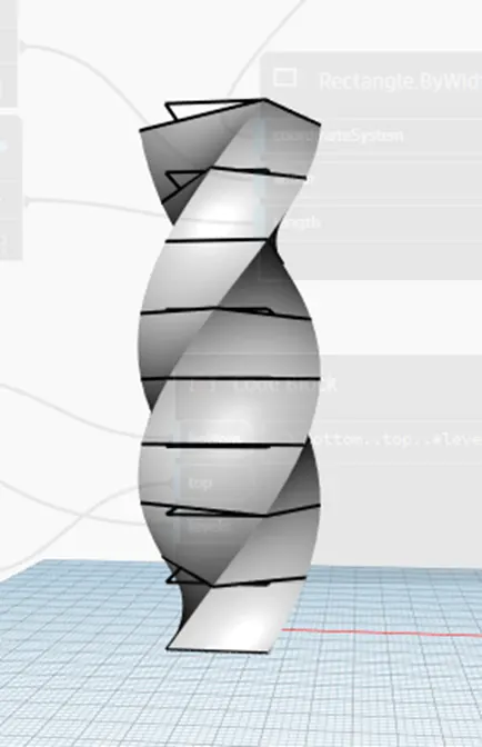
Result: A Parametric Stadium is developed in Dynamo.