Week 3 Challenge
Introduction :-
In this week we studies differents components which effect to deside the shallow foundation as well as how these components help to select the shallow foundation. Here some components which studies here are such as
A.Material strength
B.Hydrology and Geotechnical studies
C.Scour depth
D.Liquefaction
E.Shear failure
F.Bearing capacity
G.Factor of safety
Aim:-
Here we find out how to help these components effect the shallow foundation with an example
here we find out such as
1.How to hydrology and geotechnical studies helps to select the type of bridge
2.IRC Clause for select the type of bridge
3.Determination of scour depth
4.Measures to avoid scour at bridge
5.Drawing for up stream and down stream
6.What is uplift and how it effect the foundation
7.Calculate the uplift in u through
8.Measures to avoid uplift
Procedure :-
1.How to hydrology and geotechnical studies helps to select the type of bridge :-
Before select any type of foundation hydrology and geotechnical studies will effect it. If soil strata is hard strata then we select the shallow foundation. Geotechnical studeis will define the soil bearing capacity then accordinglly we select the type of foundation. After that if structure on water way then the second hydrology will effect the type of foundation such as how to find out the capacity of water ,scouring of river will get in studies of hydrology.
2.IRC Clause for select the type of bridge :-
According to IRC -05
101.15 Effective Linear Waterway Effective linear waterway is the total width of waterway of bridge at Highest Flood Level (HFL) minus the effective width of obstruction.
101.23 Highest Flood Level (HFL) Highest flood level is the level of highest flood recorded/observed or calculated from the design discharge, whichever is higher.
101.44 Submersible Bridge Submersible bridge is a bridge designed to be overtopped during floods.
105.2.3 Protection to Structure Against Barge Impact For bridges on streams where barges are plying, the bridge structure shall be protected against vessel collision forces by fenders, protection islands or any other means.
According to Clause 106 of IRC -05 are such as
106 Hydrology and Hydraulic Design
106.2 Determination of Design Highest Flood Level
106.2.1 The design flood level shall be decided on the basis of data collected during reconnaissance survey, aerial survey, satellite maps, detailed survey and hydrological and hydraulic studies and analyses made.
106.2.2 Design Highest Flood Level shall be the Highest of the following :
a) The highest of flood levels as obtained from local enquiries from aged persons. Such local enquiries should be made at 3 different locations at site.
b) Level of the highest watermarks, left on different old structures or the erosion marks on the banks
c) Highest flood level that will be able to pass the design discharge as determined from other sources as per clause 106.3
d) The highest of the levels after considering the effects of confluence, backwater and HFL because of merger of or into any other river in the influence zone upstream or downstream of site.
e) The highest level as corroborated from the records of HFL available for existing bridges, other structures like dams and spillways and gauge stations etc. on the river in upstream or downstream direction.
f) Effect of any new structure planned for future in the influence zone of the stream.
106.3 Determination of Design Discharge
106.3.1 The design discharge for which the waterway of the bridge is to be provided, shall be based on maximum flood discharge of return period of 100 years. In case where the requisite information is not available, the design discharge shall be the maximum estimated discharge determined by consideration of the following or any other rational method.
106.3.1.1 From the records of discharge observed in the stream at the site of the bridge, or at any other site in its vicinity i.e., the discharge taken for design at any other bridge site and any other irrigation structures like dam or spillway or Gauge Station on this river in the upstream direction.
106.3.1.2 From the rainfall and other characteristics of the catchment:
i) By the use of an empirical formula, applicable to that region, provided that empirical formula can predict the maximum discharge for given return period.
ii) By a recognized method, provided it is possible to evaluate, for the region concerned, the various factors employed in that method.
106.3.1.3 From stage discharge curves, if available
106.3.1.4 By the area velocity method with the help of hydraulic characteristics of the channel. In case of the river not confined within banks and flowing in larger widths, the flow width should be divided into suitable zones i.e., main flow channel, side flow channel, slow channel and stagnant or no flow channel depending upon the characteristics and various parameters which should also be considered accordingly for calculation of discharge from that zone.
106.3.1.5 By unit hydrograph method (see appendix-1) Flood estimation reports in respect of total 21 climatic sub-zones (Appendix-1(a)) in the country have been prepared based on the hydro-meteorological data collected for selected catchments of areas varying from 25 to 1500 sq.km. and are available with the Director,
Hydrology (small catchments), Central Water Commission. The methodology recommended in the relevant sub-zone report pertaining to a particular region may be followed for assessment of maximum discharge for the design of bridges.
106.3.2 Where possible, more than one method shall be adopted, results compared, and the maximum discharge fixed by judgment by the engineer responsible for the design. The bridge shall be designed for this maximum discharge. However, for catchment areas covered by sub-zones mentioned in Appendix 1(a), the maximum discharge shall be assessed on the basis of the flood estimation report for the said sub-zone.
106.3.3 Various limitations of the methods for computing the Maximum Design Discharge correctly under different flow, bed and site conditions and for a given return period, should be kept in mind and accounted for adequately while deciding the same.
106.3.4 For minor bridges, where catchment area cannot be defined, reliance may be kept on Area Velocity Method.
106.3.5 The maximum estimated discharge from the catchment area as calculated above or normal peak flood discharge from the dam/spillway if existing or being proposed in the upstream of the bridge (to be ascertained from the Irrigation Authorities), whichever is more, shall be considered for design of the bridge. Freak flood discharges or exceptional discharge of high intensity due to the failure of a dam or tank constructed upstream of the bridge need not be catered for.
106.3.6 In cases where the design discharge cannot be properly quantified and in spill zones of rivers known for flash floods, the abutments may also be designed and detailed as ‘piers’ for possible future extension.
106.4 Discharge for Design of Foundation and Protection Works To provide for an adequate margin of safety, the foundation and protection works shall be designed for a larger discharge than the design discharge given in Clause 106.3, for which reference may be made to the provisions contained in relevant IRC Codes.
106.5 Determination of Waterway
106.5.1 Linear Waterway
106.5.1.1 For natural channels in alluvial beds but with well defined banks and for all natural channels in beds with rigid in-erodible boundaries, the linear waterway shall be distance between banks at HFL, at which the designed maximum discharge determined in accordance with Clause 106.3, can be passed.
106.5.1.2 For natural channels in alluvial beds and having undefined banks, the linear waterway shall be determined from the design discharge using some accepted rational formula at the discretion of the engineer responsible for the design. One such formula for regime conditions is:
W = C√(Q)
Where,
W = regime width in meters (equal to effective linear waterway under regime condition)
Q = the maximum design discharge in m3/sec;
C = a constant usually taken as 4.8 for regime channels but it may vary from 4.5 to 6.3 according to local conditions.
106.5.1.3 The formula which is applicable for alluvial soils in regime conditions, should not be applied for clayey, bouldery or such strata. The waterway in such cases should be decided on the basis of study and analysis of site and flow conditions by adopting some rational approach (like performance of existing bridge nearby, on the same river).
106.5.1.4 In meandering flood plains and in deltaic regions, the waterway proposed may be as in above clauses, but guide bunds, flood embankments or other river training works should be provided to train the river to flow through the bridge. Hydraulic or Mathematical model studies may be required to ascertain the flow conditions, and design parameters for the training works and the required waterway.
106.5.1.5 If the river is of a flashy nature and the bed does not submit readily to the scouring effects of the flood, the linear waterway should be determined by the area velocity method, taking into account the design flood level and its water spread, the characteristics of the bed materials and the water surface slope.
106.5.1.6 In a hilly terrain, the minimum waterway under the bridge should be kept same as the linear waterway at HFL.
106.5.1.7 In sub-hilly terrain/trough terrain, waterway should be decided after carefully studying the past history of river behavior and flow conditions, as river is usually unstable and changing course periodically resulting in a fan shaped delta type formations, requiring more waterway than normally required by formula.
106.5.1.8 In case a new bridge is to be constructed, close to an existing bridge for the purpose of widening or providing extra carriageway, the waterway provided in the new bridge should usually be kept the same as in the old bridge unless there are specific reasons. If the waterway is to be kept different, then bridges should be provided with smooth inlet and outlet transitions.
106.5.1.9 For artificial channels (irrigation, navigation and drainage), the linear waterway should be adequate to pass the full discharge at designed velocity, but concurrence shall invariably be obtained from the authority controlling the channel. If it is proposed to flume the channel at the site of the bridge, this fluming shall be subject to the consent of the same authority and in accordance with the essential requirements.
106.5.1.10 The waterway, as worked out from the formula or decided otherwise, should be compared with linear waterway at HFL corresponding to the design flood discharge and the difference in the two should be analyzed and reconciled before finally deciding the waterway to be provided.
106.5.2 Restricted Waterway
106.5.2.1 The linear waterway as calculated above can be restricted by careful consideration of the resulting effects on flow conditions, scour, afflux and other site condition in the individual cases. No restriction in waterway should be considered for well defined and confined flow.
106.5.2.2 In hilly terrain the linear waterway at HFL should not be restricted because that will cause undesirable hydraulic jumps as the flow in such a terrain is usually super critical.
106.5.2.3 For unstable meandering rivers flowing through a number of sub channels separated by land or shallow section of nearly stagnant water and having width much in excess of the regime width, or channels flowing over large widths with small depths, the restriction of waterway may be considered. In such cases, it may be necessary to constrict the channel by providing training and protection works to prevent the main channel from wandering about freely and for minimizing the resultant oblique attack on bridge foundations
and approaches. The extent of constriction and the design of training works in such cases should, preferably, be decided on the basis of model studies, keeping in view the ultimate economy, safety, durability and aiming at optimal recurring maintenance needs of structure as well as river training works.
106.5.2.4 In case of bridge being located at bends, curves or oblique to flow, the waterway gets restricted. The available waterway normal to the flow should be worked out and this should be accounted for in the design.
106.5.2.5 The restriction of waterway will result in afflux on the upstream of bridge. The effect of this afflux on the velocity, scour and submergence of surrounding area should be considered in the design. The consideration of these effect and comparison of consequent costs in the two cases, will decide the limit of restriction in the linear waterway.
106.5.2.6 If the waterway has to be restricted to such an extent that the resultant afflux will cause the channel to discharge at erosive velocities, protection against damage by scour shall be afforded by providing deep foundations, curtain or cutoff walls, rip-rap, bed pavement or other suitable means.
106.5.3 Effective Linear Waterway
106.5.3.1 The linear waterway or restricted waterway worked out as above shall be reduced because of the obstruction caused by piers or obliquity of flow in the river at the bridge site.
106.5.3.2 For calculating the effective linear waterway the width of obstruction due to each pier shall be taken as the mean submerged width of the pier and its foundation up to the normal scour level. The obstruction at the ends due to the abutments or pitched slopes duly protected shall be ignored. For other flow conditions, actual obstruction due to pier and foundation normal to the flow should be worked out and considered in design.
106.5.3.3 Effect of presence of Dams, Barrages, Weirs, Sluice Gates etc. on the hydraulic characteristics like causing obliquity and concentration of flow, scour, silting of bed, change in flow levels, bed levels etc. should be studied and analysed while deciding the waterway.
These should invariably be decided after collection of data from the concerned regulatory authorities and after discussions with them.
106.5.3.4 The effect on linear waterway and hydraulic particulars should be taken care of in the design of a bridge, if constructed in the close proximity of an existing bridge.
106.5.3.5 In case of tidal zones, where it is decided to adopt measures likely to affect the volume of the tidal flow and other characteristics of the tide, it shall be ensured that no port or harbor or other installations in the proximity of the bridge are adversely affected.106.6 Determination of Afflux
106.6.1 If the waterway is restricted as per Clause 106.5.2, it will cause afflux at the bridge and design HFL will accordingly be raised.
106.6.2 The afflux shall be calculated by using any suitable method based on conservation of energy or momentum. In absence of any rigorous method, the afflux may be calculated by using Molesworth formula as given below :
h = (V2/17.88 + 0.015) x ((A/a)2– 1), where :
h = afflux (in meters)
V = average velocity of the water in the river prior to constriction (in m/sec)
A = unobstructed sectional area of the river at proposed site (in sq. m)
a = constricted area of the river at proposed site (in sq. m)
106.6.3 The effect of afflux on the velocity, submergence area and scour etc shall be worked out and accounted for in the design.
106.7 Freeboard
106.7.1 The freeboard for the approaches to high level bridges, where water spreads along the approaches, shall not be less than the minimum values specified in relevant IRC code for road designs.
106.7.2 For the aggrading rivers in Himalayan foot-hills and flood-prone areas or NorthEastern States, North Bengal etc. and where ever required for some specific reason, the freeboard shall be suitably increased.
106.8 Vertical Clearance over HFL
106.8.1 The vertical clearance shall ordinarily be provided as given in the following clauses.
106.8.2 For openings of high level bridges, which have a flat soffit or soffit with a very flat curve, the minimum clearance shall be in accordance with the following table. The minimum clearance shall be measured from the lowest point of the deck structure inclusive of main girder in the central half of the clear opening unless otherwise specified.
Discharge in Cumecs Minimum Vertical Clearance in mm.
Upto 0.3 150
Above 0.3 & upto 3.0 450
Above 3.0 & upto 30.0 600
Above 30.0 & upto 300 900
Above 300 & upto 3000 1200
Above 3000 1500
106.8.3 For arched openings of high level bridges having overhead decking, the clearance below the crown of the arch shall not be less than one tenth of the maximum depth of water plus one-third of the rise of the arch intrados.
106.8.4 No part of the bearings shall be at a height less than 500 mm above the design highest flood level, taking into account afflux.
106.8.5 In the case of artificial channels having controlled flows and carrying no floating debris, vertical clearances lesser than that specified in Clause 106.8.2 & 106.8.3 above may be provided.
106.8.6 In the case of bridges in sub-mountainous region and across aggrading rivers, silting of the bed of the river should also be taken into consideration while fixing the vertical clearance.
106.8.7 In case of bridges across tidal rivers, creeks, sea, the vertical clearance shall be provided keeping in view the HTL and normal wave/splash effects.
106.9 Determination of the Maximum Depth of Scour
106.9.1 The probable maximum depth of scour to be taken for the purpose of designing foundations for piers, abutments and river training works shall be estimated after considering all local conditions over a reasonable period of time.
106.9.2 Wherever possible, soundings for the purpose of determining the depth of scour shall be taken in the vicinity of the site proposed for the bridge. Such soundings are best taken during or immediately after a flood before the scour holes have had time to silt up appreciably. Allowance shall be made in the observed depth for increased scour resulting from:
i) The design discharge being greater than the flood discharge.
ii) The increase in velocity due to obstruction in flow caused by construction of the bridge.
iii) The increase in scour in the proximity of piers and guide bunds.
106.9.3 Scour
106.9.3.1 The following theoretical method may be adopted when dealing with the natural channels flowing over scourable beds for the estimation of mean depth of scour ‘dsm’ in meters.
dsm=1.34[Db^2/Ksf]^1/3
Where :
Db = The discharge in Cumecs per meter width. The value of “Db ” shall be the
maximum of the following:
i) The total design discharge divided by lower of the effective linear waterway between abutments or guide bunds, and theoretical linear waterway.
ii) The value obtained taking into account any concentration of flow through a portion of the waterway assessed from the study of the cross-section of the river. Such modification of the value may not be deemed applicable to minor bridges of length upto 60 m.
iii) Actual observations, if any.
Ksf = the silt factor for a representative sample of the bed materials obtained
down to the maximum anticipated scour level and is given by the expression 1.76√dm in case of sandy soils (having particle size between 0.04 mm to 2.00 mm), where “dm” is the weighted mean diameter of the
bed material in mm. Clayey beds having weighted diameter less than 0.04 mm offers more resistance to scour than sand. In absence of any accepted rational formula or any data of scour at the site of the proposed bridge, the following theoretical calculations may be adopted :
i) In case of soil having f< 15o and c (cohesion of soil) > 0.2 Kg/cm2,‘Ksf’ shall be calculated as follows :
Ksf = F(1+√c), where ‘c’ is in Kg/cm2
Where,
F = 1.50 for f> 10º and < 15º
= 1.75 for f > 5º and < 10º
= 2.00 for f < 5º
ii) Soils having f > 15º will be treated as sandy soil even if ‘c’ is more than 0.2 Kg/cm2 , and silt factor will be as per provision for sandy soil.
Note:
i) The effective linear waterway shall be determined in accordance with Clause 106.5.3, and in no case shall exceed the value assessed as per Clause 106.5.1.2.
ii) A typical method of determining “dm” is set forth in Appendix-2.
iii) The value of Ksf to be adopted for the purpose of design should be determined after laboratory testing of the representative samples of bed materials collected during the sub-soil exploration.
106.9.3.2 If there is any predominant concentration of flow in any part of waterway due to bend of the stream in immediate upstream or downstream or for any other reason, like wide variation in type of bed material across the width of channel, then mean scour depth may be calculated dividing the waterway into compartments as per the concentration of flow.
106.9.3.3 Maximum scour depth The maximum scour depth below the highest flood level (HFL), which is to be considered for the purpose of design of foundations, protection works, river training works etc. shall be in
accordance with relevant IRC Standards, duly taking into account the mean scour depth dsm and obstructions due to piers and abutments.
106.9.3.4 If a river is of flashy nature and the bed does not lend itself readily to the scouring effect of floods, the formula for dsm given in the Clause 106.9.3.1 shall not apply. In such cases the maximum depth of scour shall be assessed from actual observations.
106.9.3.5 Bridge located across streams having gravel or boulder beds (normally having weighted diameter more than 2.00 mm), there is yet no rational formula for determining scour depth. However, the formula given in Clause 106.9.3.1 may be applied with a judicious choice of value of Db and Ksf and the results compared with the actual observations at the site or from experiences on similar structure nearby and their performance and decision taken based on sound engineering judgment.
106.9.3.6 Obstruction in the channel bed, likely to divert the current or cause undue disturbed flow or scour and thereby endanger the safety of the bridge, shall be removed as far as practicable from within a distance upstream and downstream of the bridge not less than the length of the bridge subject to a minimum of 100 meters in each direction. Attention shall be given to river training and protection of banks over such lengths of the river as required. In case it is not possible to remove such obstructions, its effect on scour shall be considered.
106.10 River Training and Protection Works
106.10.1 The slopes, in front of abutments and the portion of bridge approaches falling in the flood zone, shall be provided with suitably designed pitching and launching apron.
106.10.2 In case of the uncertain and changing flow conditions, adequate river training works shall be provided for protection of banks, embankments and directing the river to flow under the bridge.
106.10.3 After collecting the required data, studying and analyzing the river flow conditions etc. and necessary model studies, wherever required, the protection works shall be designed as per provisions of IRC:89 or other specialist literature.
106.11 Hydraulic and Mathematical Model Studies
106.11.1 These Studies should be Carried Out Wherever Necessary, such as :
● in case of big rivers with large discharge having uncertain and complex flow conditions and for other abnormal situations
● when the linear waterway and scour cannot be accurately calculated or
● when the protection and river training works cannot be designed reliably because of the uncertain or complex conditions.
106.11.2 The studies should be carried out at the reputed, reliable and accredited institutions only where requisite facilities are available.
106.11.3 The Site and Contour surveys for these studies should be done very carefully, with precision and it should be ensured that these along with bed materials are correctly represented in the Model.
3.Determination of scour depth :-
As per IRC 78, Clause no-703.2 the mean scour depth can be calculated as
The mean scour depth below Highest Flood Level (HFL) for natural channels flowing over scourable bed can be calculated theoretically from the following equation:
dsm=1.34(Db^2/ksf)^1/3
where ,
Db = The design discharge for foundation per metre width of effective waterway.
K sf = Silt factor for a representative sample of bed material obtained upto the level of anticipated deepest scour.
703.2.1 The value of Db may be determined by dividing the design discharge for foundation by lower of theoretical and actual effective linear waterway as given in IRC:5.
703.2.2 'Ksf ' is given by the expression 1.76(dm)^0.5,dm being the weighted mean diameter in millimetre.
703.2.2.1 The value of K sf for various grades of sandy bed are given below forready reference and adoption:
Type of bed material dm Ksf
Coarse silt 0.04 0.35
Silt/fine sand 0.081 to 0.158 0.5 to 0.7
Medium sand 0.223 to 0.505 0.85 to 1.25
Coarse sand 0.725 1.5
Fine bajri and sand 0.988 1.75
Heavy sand 1.29 to 2.00 2.0 to 2.42
703.2.2.2 No rational formula or data for determining scour depth for bed material consisting of gravels and boulders (normally having weighted diameter more than 2.00 mm) and clayey bed is available. In absence of any data on scour for such material, the mean scour depth may be calculated following the guidelines given in Appendix-1.
703.2.3 If there is any predominant concentration of flow in any part of waterway due to bend of the stream in immediate upstream or downstream or for any other reason, like, wide variation of type of bed materia! across the width of channel, then mean scour depth may be calculated by dividing the waterway into compartments as per the concentration of flow.
703.2.4 In case of bridge mainly adopted as balancer, the mean scour depth 'd sm ' may be taken as (Highest Flood Level-Lowest Bed Level) divided by 1.27.
703.2.5 Scour depth may be determined by actual observations wherever possible. This is particularly required for clayey and bouldery strata. Soundings, wherever possible, shall be taken in the vicinity of the site for the proposed bridge and for any structures nearby. Such soundings are best during or immediately after a flood before the scour holes have had time to be silted up. The mean scour depth may be fixed based on such observations and theoretical calculation.
703.3 Maximum Depth of Scour for Design of Foundation
703.3.1 The maximum depth of scour below the Highest Flood Level (HFL) for the design of piers and abutments having individual foundations without any floor protection may be considered as follows.
703 .3.7.7 Flood without seismic combination
i) For piers - 2.0 d sm
ii) For abutments - a) 1 .27 d sm with approach retained or lowest bed level whichever is deeper.
b) 2.00 d with scour all around.
703.3.7.2 Flood with seismic combination
For considering load combination of flood and seismic loads (together with other appropriate combinations given elsewhere) the maximum depth of scour given in Clause 703.3.1 .1 may be reduced by multiplying factor of 0.9.
703.3.1.3 For low water level (withoutflood conditions) combined with seismiccombination maximum level of scour below high flood level can be assumed as 0.8 times scour given in Clause 703.3.1.
NOTE : In respect of viaduct/ROB having no possibility of scour, resistance of soil may be considered below depth of excavation for services construction, or 2.0 m below ground level whichever is greater.
703.3.2 For the design of floor protection works for raft or open foundations, the following values of maximum scour depth may be adopted:
i) In a straight reach 1 .27 d sm
ii) In a bend 1.50 d sm or on the basis of concentration of flow The length of apron on upstream may be 0.7 times of the same on downstream.
703.4 Special studies should be undertaken for determining the maximum scour depth for the design of foundations in all situations where abnormal conditions, such as, the following are encountered:
i) a bridge being located on a bend of the river involving a curvilinear flow, or excessive shoal formation, or
ii) a bridge being located at a site where the deep channel in the river hugs to one side, or
iii) a bridge having very thick piers inducing heavy local scours, or
iv) where the obliquity of flow in the river is considerable, or
v) where a bridge is required to be constructed across a canal, or across a river downstream of storage works, with the possibility of the relatively clear water inducing greater scours, or
vi) a bridge in the vicinity of a dam, weir, barrage or other irrigation structures where concentration of flow, aggradations/degradation of bed, etc. are likely to affect the behavior of the structures.
vii) An additional tow-lane bridge when located near to the existing bridge, on major rivers.
NOTE: These studies shall be conducted for the increase discharge calculated vide Clause 703.1.1.
703.5 If a river is of a flashy nature and bed does not lend itself readily to the scouring effect of floods, the theoretical formula for dsm and maximum depth of scour as recommended shall not apply. In such cases, the maximum depth shall be assessed from actual observations.
4.Measures to avoid scour at bridge :-
there are some ponit where we need to focus so we can avoid the scouring at foundation
1.proper investigation of soil for properties of soil
2.Actual discharge and HFL calculation
3.Protection of foundation against scouring
4.Proper depth of foundation
these some point should be in mind for scouring
5.Drawing for up stream and down stream :-
According to IRC 89 clause no 10 protection of floor are such as
10. FLOOR PROTECTION
10.1 For bridges where adoption of shallow foundations becomes economical by restricting the scour, floor protection to bridges must be provided. The floor protection will comprise of rigid flooring with curtain walls and flexible apron to check scour, washing away or disturbance by piping action, etc. Usually performance of similar existing works is the best guide for finalizing the design of new works.
10.2 Suggested Specifications
10.2.1 Excavation for laying foundation and protection works shall be carried out as per specifications under proper supervision. Before laying the foundation and protection works the excavated trench shall be thoroughly inspected by the Engineer-in-charge to ensure that:
(i) There are no loose pockets, unfilled depressions left in the trench.
(ii) The soil at the founding level is properly compacted to true lines and level.
(iii) All concrete and other elements are laid in dry bed.
10.2.2 Rigid flooring: The rigid flooring shall be provided under the bridge and it shall extend for a distance of at least 3 m on upstream side and 6 m on downstream side of the bridge. However, in case the splayed wing walls of the structure are likely to be longer, the flooring shall extend up to the line connecting the end of wing walls on either side of the bridge.
10.2.2.1 The top of flooring shall be kept 300 mm below the lowest bed level.
10.2.2.2 Flooring shall consist of 150 mm thick flat stone or bricks on edge, with cement mortar 1:3 laid over 300 mm thick cement concrete M-30 grade laid over a layer of 150 mm thick cement concrete M-15 grade. Joints at suitable spacings (say 20 m) may be provided.
10.2.3 Curtain walls: The rigid flooring shall be enclosed by curtain walls (tied to the wing walls) with a minimum depth below floor level of 1.27 times of depth of scour on upstream side and 1.27 times the depth of scour + 0.5 m on downstream side. The curtain wall shall be in cement concrete M-30 grade/brick/stone masonry in cement mortar 1:3. The curtain off wall can be attached with raft slab and should not be less than 300 mm thick with M 30 grade concrete. It should be designed as normally reinforced PCC wall with 0.12%
steel of Fe 500 grade in each direction on both faces, with clear cover of 75 mm. These walls should not have structural continuity or moment connection with RCC slab, but the joint should be leak tight. The cutoff wall should be taken at lease 300 mm below the mean depth of scour calculated as per IRC:5. However, the total minimum depth below floor shall not be less than 2 m on upstream side and 2.5 m on the downstream side below the top of the floor. In case the substratum with continuous layer of stiff non-securable clay in the
neighborhood of downstream of cut-offs a judicious adjustment in the depth of upstream and downstream cut-offs shall be made to avoid building up pressure under the raft (refer clause 15.1.1 of IS:6966).
10.2.4 Flexible apron
10.2.4.1 The thickness of flexible apron shall be 0.6 m for Manning’s velocity up to 3 m/s at raft top and for velocity more than 3 m/s the same shall be 1.0 m comprising loose stone boulders (weighing not less than 40 Kg). Flexible apron shall be provided beyond the curtain walls for a minimum distance of 3 m on upstream side and 5 m on downstream side. Where required size stones are not economically available, cement concrete blocks or stones in mechanically woven double twisted wire mesh gabion or mattress with rockfill properties as per Table 6 of IRC:SP:116 shall be used in place of isolated stones.
10.2.5 Wherever scour is restricted by provision of flooring/flexible apron, the work of flooring/apron etc., should be simultaneously completed along with the work on foundations so that the foundation work completed and left to itself is not endangered.
10.2.6 One dimensional mathematical model like water routing and backwater models to solve problems such as dam break, flood wave transmission, effect of bridge constriction etc. were commonly in use before the introduction of computers. Now with the easy access to mainframe computer and personal computers with large memories, it has become possible to develop software and study the morphological changes of short and long duration by simulation models. Institutes such as Central Water Commission, Central Water and Power
Research Station, Pune, National Institute of Hydrology, Roorkee, and some of the State Irrigation Research Institutes and Indian Institute of Technology at Delhi, Bombay etc. have developed suitable software to study these aspects in river engineering.
6.What is uplift and how it effect the foundation :-
Uplift pressure:-
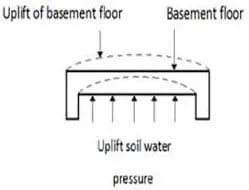
Uplift pressure, which is also known as hydrostatic uplift, is an upward pressure applied to a structure that has the potential to raise it relative to its surroundings. It is the condition of greater pore water pressure than the overburden pressure of the structure.The uplift pressure can be problematic if it is greater than the weight of the structure exerted downwards.
The structure must be designed properly to provide greater resistance against uplift forces in order to prevent risks due to water pressure. So, the uplift pressure must be taken into consideration during design stage since rehabilitation and maintenance of foundation cannot be carried out easily in the future.
How to Check for Uplift Pressure
The weight of the substructure should be greater than uplift pressure in order to meet the requirements.The downward load should at least greater than 25% compared to the upward load due to hydrostatic load. The following expression can be used to check the occurrence of uplift force below the structure under considerations:
`(phi W)/(w(h+1)>=1.25`
where ,
Ø: mass reduction factor, can be taken as 0.90
W: the mass of the structure
w: specific weight of water
h: height of water from the water table to the bottom of the foundation
1: Factor of safety
Consequences of Uplift Pressure:-
- It reduces the effective weight of the structure.
- Endanger stability of the structure
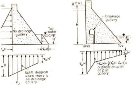
Strategies for Prevention of Uplift Pressure
Dewatering procedure may help to control the water away from construction site, but it cannot keep the dewatering the whole life span of the construction as it is not an economical move. There are number of methods by which the influence of uplift pressure is avoided.
1.Toeing in the Foundation into the Surrounding Ground
2.Increase Self-weight of the Structure
3.Ground Anchors
4. Piling Method
7.Calculate the uplift in u through:-
here given data as ,
silt factor -3
design discharge -1000 cumsec
linear waterway -128 m
so,
Db=Max discharge
=design discharge / Linear waterway
=1000/128
=7.812 cumsec/m
so ,
mean scour depth
=1.34((Db)^2/Ksf)^1/3
=1.34((7.812)^2/3)1/3
=3.657m
flood without seismic condition
-for pier
scour depth =2*mean depth of scour
=2*3.657
=7.315 m
For Abutment
over all =2*mean depth of scour
=2*3.657
=7.315m
With approach retained =1.27*mean depth of scour
=1.27*3.657
=4.646 m
Flood with seismic condition
for pier
scour depth =0.9*7.315
=6.584m
For Abutment
Over all =0.9*7.315
=6.584m
With approach retained =0.9*4.646
=4.181m
8.Calculation of uplift force on u through :-
as per attached copy of calculation