Week 3 Challenge
Q1.How hydrology and geotechnical studies (preliminary and detail studies, zone of influence) are used in fixing span as per IRC standards and type of bridge. Mention the clauses applicable for the same.
Determine the scour depth at the pier and abutment location having silt factor =3
Design discharge = 1000 cumecs
Linear waterway = 128
Ans:
- Design discharge helps in deciding total length of the bridge,depth of foundation and river training works if required.
- Discharge can be calculated with calculating the catchment area and then, discharge formulas can be used to calculate the velocity and discharge of the river.
Bridge types as per Clauses as per IRC 5
101.6 Bridge
A bridge is a structure having a total length of above 6 m for carrying traffic or other moving loads across a channel, depression, road or railway track or any other obstruction.
101.13 Culvert
Culvert is a structure having a total length of upto 6 m between outer faces of walls, measured at right angles. Cross drainage structures with pipes will be termed as culvert, irrespective
of length.
101.39 Road Over Bridge (ROB)
Road Over Bridge is a bridge built over the Railway tracks.
101.40 Road Under Bridge (RUB)
Road under bridge is a structure built beneath the Railway tracks.
101.44 Submersible Bridge
Submersible bridge is a bridge designed to be overtopped during floods.
Four main factors were identified in the selection of the appropriate bridge types.
These factors include
- Geography
- Loading
- Aesthetics
- Cost
The bridge located within unique geological features that will affect the selection of the bridge types
Scour depth calculation
Data given
Silt factor =3
Design discharge = 1000 cumecs
Linear waterway = 128
Soln :
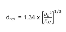
Db = 1000/128 = 7.82 cumecs/m
Ksf,Silt factor = 3
so,dsm = 1.34 x ((7.82^2)/3)^1/3
dsm = 3.62
Q1b. what measures can be taken to avoid scour at bridge for shallow foundation. Also draw the section of measures on the downstream and the upstream side.
(Note: Draw all the drawings to the scale and neatly)
Ans :
Methods to prevent scouring
- Provide protection works -The rigid flooring should be provided under the bridge and it should extend for a distance of at least 3 m on upstream side and 5 m on down stream side of the bridge. However, in case the splayed wing walls of the structure are likely to be longer, the flooring should extend upto the line connecting the end of wing walls on either side of the bridge. The top of flooring should be kept 300 mm below the lowest bed level. Flooring should consist of 1 50 mm thick flat stone/bricks on edge in cement mortar 1 :3 laid over 300 mm thick cement concrete Ml 5 grade laid over a layer of 1 50 mm thick cement concrete M10 grade. Joints at suitable spacings (say 20 m) may be provided.
- Providing flexible and rigid aprons - Flexible apron 1 m thick comprising of loose stone bouiders (weighing not less than 40 kg) should be provided beyond the curtain walls for a minimum distance of 3 m on upstream side and 6 m on downstream side. Where required size stones are not economically available, cement concrete blocks or stones in wire crates may be used in place of isolated stones. In this context, relevant provision in IRC:89-1997 is also referred.20. 1 .2.5. Wherever scour is restricted by provision of flooring/flexible apron, the work offlooring/apron etc., should be simultaneously completed alongwith the work on foundations so that the foundation work completed is not endangered.
- Provide Cut off walls / curtain walls - The rigid flooring should be enclosed by curtain walls (tied to the wing walls) with a minimum depth below floor level of 2 m on upstream side and 2.5 m on downstream side. The curtain wall should be in cement concrete Ml 5 grade or brick/stone masonry in cement mortar 1:3. The rigid flooring should be continued over the top width of curtain walls. In this context,
relevant provision in "Guidelines for design and construction ofriver training and control works for road bridges", IRC: 89-1997 is also referr - Providing adequate depth of foundation Reduction of scouring is possible by different approaches, using different countermeasures. Ripraps and geo bags reduce the scouring up to 40-50%. Collars reduces the scouring at great extent if it is placed at or below river bedlevel. Rectangular collar reduces the scouring to 79% Collar having dimension 1.5 to 2 times the pier dimension reduces the scouring in the range 55% to 96% Slot is most efficient if the angle between slot and the current is in the range 20°. If the slotwidth is one fourth of the pier diameter the scour reduction is 20% and if the width is one half of the pier diameter, the scour reduction is 30%.If the slot is placed at river bedlevel,it reduces the scouring to 60-88%. Scouring reduction of 100% is possible by using both collar and slot incombination.
Q 1.c What is uplift and how it can affect the foundation. (loss of contact)
Calculate the uplift in U trough of below section with height 3,4,5 meters. with water level on top of ramp wall level .
What are different measures that can be taken to avoid uplift.
ANS :
For H=3m
| Width of base slab | = | 10.21 | (9.2+0.41+0.6) |
| Area per m width (A) | = | 10.21 | m2 |
| Ỵw | = | 10 | kN/m3 |
| H | = | 3 | m |
| depth of base slab | = | 0.68 | m |
| h | = | H+depth of base slab | |
| 3.68 | m | ||
| Uplift pressure | = | Ỵw*h | |
| = | 36.8 | kN/m2 | |
| Uplift force per m | = | Ỵw*h*A | |
| = | 375.728 | kN/m | |
For H=4m
| Width of base slab | = | 10.21 | (9.2+0.41+0.6) |
| Area per m width (A) | = | 10.21 | m2 |
| Ỵw | = | 10 | kN/m3 |
| H | = | 4 | m |
| depth of base slab | = | 0.68 | m |
| h | = | H+depth of base slab | |
| 4.68 | m | ||
| Uplift pressure | = | Ỵw*h | |
| = | 46.8 | kN/m2 | |
| Uplift force per m | = | Ỵw*h*A | |
| = | 477.828 | kN/m | |
For H=5m
| Width of base slab | = | 10.21 | (9.2+0.41+0.6) |
| Area per m width (A) | = | 10.21 | m2 |
| Ỵw | = | 10 | kN/m3 |
| H | = | 5 | m |
| depth of base slab | = | 0.68 | m |
| h | = | H+depth of base slab | |
| 5.68 | m | ||
| Uplift pressure | = | Ỵw*h | |
| = | 56.8 | kN/m2 | |
| Uplift force per m | = | Ỵw*h*A | |
| = | 579.928 | kN/m | |
Methods to avoid uplift
- Toeing in the Foundation into the Surrounding Ground
When a substructure is built inside an open excavation or temporary cofferdam, the base slab or raft foundation can be extended outside perimeter to increase resistance to uplift.
The weight of backfill material on the tied-in foundation increase the weight of the structure against uplift pressure. This method is not feasible where a diaphragm or secant pile wall is used as a permanent retaining structure.
2. Ground Anchors
Pre-stressed anchors can be used as a temporary measure to counteract uplift forces. Permanent application of ground anchors is limited by concerns about their long-term performance with respect to corrosion.