Week 3 Challenge
Question 1 - How hydrology and geotechnical studies (preliminary and detail studies, zone of influence) are used in fixing span as per IRC standards and type of bridge. Mention the clauses applicable for the same.
Determine the scour depth at the pier and abutment location having silt factor =3
Design discharge = 1000 cumecs
Linear waterway = 128 m
Answer 1 -
According to IRC 5 Cl.106.3 and Cl.106.4, the hydrology study provides us with all the information we need to determine the total length of the bridge, including design discharge. It offers a high flood level at which to decide on bridge height and type. It offers information on the scour level used to determine foundation level. It offers water velocity, based on which the kind of substructure is chosen. based on Cl. 104.1.3. The Survey of India's topographical sheets can be used as a starting point for the preliminary site selection, and they can be reinforced by a physical survey or an analysis of satellite photos of the area, which can be obtained from the National Remote Sensing Agency. For the purpose of spanning rivers with ill-defined cross sections and sizable flood plains, a model study may be necessary. HFL and scour detailed studies must be completed in accordance with IRC 78 Cl. 703.
The roadway design, bridge design, and construction employees will get the site conditions, design recommendations, and geotechnical report via this channel. IRC 78 Cl.704 states.
PRELIMINARY STUDIES :
Preliminary Stage is the the stage when the Bridge site is being Analysed, also Site Selection is Done and the alingment of the Bridge is finalysed as the Bridge will create a minimum skew angle and must be allign properly with the road alingment, the preliminary study also gives us the information about the bed material in River.
DETAILED STUDIES :
In order to establish the design parameters that affect the choice and design details of the various structural elements, especially the foundation type, it is necessary to ascertain the characteristics of the existing geo-materials, such as soil, rock, bed material in water courses, etc., in the zone of influence of the proposed bridge sites.
STUDIES DURING CONSTRUCTION :
To verify the geo-material properties developed in Detailed Studies on the basis on which design decisions are taken, and to re-verify the same or alter to meet the conditions met at particular foundation locations.
ZONE OF INFLUENCE :
The above-mentioned "zone of influence" is defined as the entire length of the bridge, including a portion of the wing/return wall and part of the approaches, which includes, but is not limited to, the entire flood zone for water courses, and up to a depth below the proposed foundation levels, where the influence of stresses due to the foundation is likely to affect the behaviour of the structure, such as settlement and subsidence (the process by which land or buildings sink to a lower level) under ground flow of water, among other things. Zones where the hydraulic characteristics of river water are expected to change, impacting flow patterns, scour, and erosion, should be included in the width of the land strip on either side of the proposed project.
Bridge, IRC 5 Cl.101.6
A bridge is a building with a total length of more than 6 metres that spans a waterway, depression, road, railroad track, or any other impediment to convey traffic or other moving loads.
Culvert, IRC 5 Cl.101.13
A culvert is a construction with an overall length between the outer faces of walls of up to 6 m, measured at a right angle. Regardless of length, cross drainage structures with pipes are referred to as culverts.
101.17 of IRC 5 (Foot Over Bridge) (FOB)
A foot over bridge is a bridge designed solely for pedestrian usage that crosses a road or other impediment.
Road Over Bridge, IRC 5 Cl.101.39 (ROB)
Over the railroad tracks is a bridge called the Road Over Bridge.
Road Under Bridge, IRC 5 Cl.101.40 (RUB)
A construction known as a road under bridge was constructed beneath railroad tracks.
--------------------------------------------------------------------------------------------------------------------------------------------
Data Given :
- Silt Factor = 3
- Design Discharge = 1000 cumecs
- Linear Waterway = 128 m
According to IRC 78, the mean scour depth below the Highest Flood Level (HFL) for natural channels flowing over scourable bed can theoretically be calculated using the following equation:
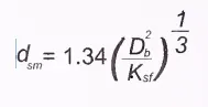
- Where Db is the foundation design discharge per metre width of effective waterway.
- Ksf = Silt factor for a representative sample of bed material obtained up to the expected deepest scour level.
According to IRC SP 13, Db is the total design discharge divided by the effective linear waterway between abutments or guide bunds.
Regime Width of the Stream
Linear water way W=4.8Q(1/2) =4.8*(1000)1/2 = 151.7m (128m)
Db = 1000/128 = 7.81m3/s per metre of width
Ksf = 3
dsm = 1.34 x (((7.81 x 7.81 ) / 3 ) ^1/3) = 3.66 m
Pier maximum scour depth = 2xdsm = 7.32m.
Maximum scour depth for abutment with retained approach or lowest bed level, whichever is greater = 1.27xdsm = 4.65m
Maximum scour depth for abutment with all-around scour = 2xdsm = 7.32m.
Question 2 - What measures can be taken to avoid scour at bridge for shallow foundation. Also draw the section of measures on the downstream and the upstream side.
Answer 2 - There are various measures that can be taken to avoid the scouring such as :
- Provide Protection at the embankments of the bridge.
- Provide Flexible and Rigid Aprons.
- Selection of adequate Depth for the Foundations.
- Provide Cut Off Wall / Curtain Walls.
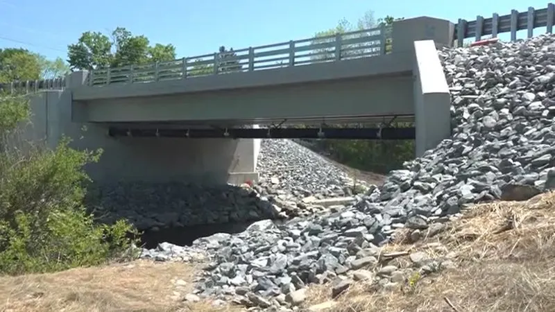
Provide Protection at the embankments of the bridge : Provide Stone Pitching at the approach roads and down the slope provide Toe Walls to restrict, this method reduces the scouring at the edges of the banks of the bridge.
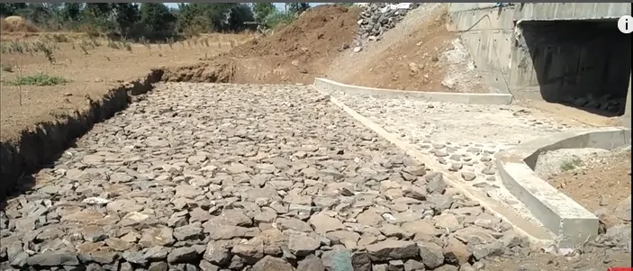
Provide Flexible and Rigid Aprons : As per IRC SP 13-2004 and IRC SP-20-2002 the bed of the Bridge foundations can be protected by the help of Aprons, these are provided in both directions U/S & D/S, it creates a finished surface in the bed of the river by the help of which water moves efficiently and quickly without causing any scouring at the foundations of the bridge.
Selection of adequate Depth for the Foundations : The Selection of the Foundations is very important, the designer requires the soil investigation report which clearly states the boring data, parametres such as S.P.T. value, crust details and safe bearing capacity of the soil. By Analysing all the data designers opt for shallow or pile foundations.
If the Safe Bearing Capacity of the soil is less foundations should be placed in more depth but as the depth of the foundations increases cost of the bridge is also increases if the depth of the foundation increases by 5-6m and the safe bearing capacity of the bridge is still not reachable the designer should opt for Pile Foundations which will results in overall lesser cost for the foundations and making bridge economic.
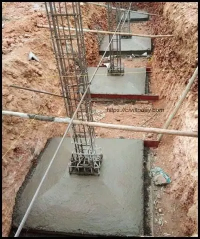 Shallow Foundations
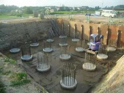 Pile Foundation
Provide Cut Off Wall / Curtain Walls : The Curtain Walls are Provided to protect the sides of the abutments, if the river stream is wide and the bridge is narrow then curtain walls are provided at the edges of the abutments in both U/S & D/S sides.
By the help of Curtain walls it diverts the river water into the bridge section, river stream is restricted to flow through the abutment edges which also reduces the embankment cutting problem and protects the bridge embankments from washing over.
Cut of walls greatly reduces the river's stream velocity which protects the bed of the bridge from scouring.

Question 3 - What is uplift and how it can affect the foundation. (loss of contact)
Answer 3 - Any upward force supplied to a structure that has the power to elevate it in relation to its surroundings is referred to as an uplift pressure. Uplift forces may result from pressure from the subsurface, surface water, and other factors.
The ground water head at the deep aquifer below the subgrade may be sufficiently high to cause the soil layers to weaken when there is an impermeable layer between the bottom of the excavation and it.
High rainfall can cause water pressure to impose an uplift force on a structure, for instance by expanding clay soils. If the upward forces are greater than the downward forces the structure is applying, this could be troublesome. The structure needs to be built with more resistance to uplift forces and a drainage system to alleviate water pressure in order to avoid this risk.
The designer should check for any negative base pressure in the design and if its developing then the designer should opt for increase in the size of foundations or Provide anchorage at the base of the foundations.
Question 4 - Calculate the uplift in U trough of below section with height 3,4,5 meters. with water level on top of ramp wall level .
Answer 4 -
For H=3m
| Width of base slab | = | 10.21 | (9.2+0.41+0.6) |
| Area per m width (A) | = | 10.21 | m2 |
| Ỵw | = | 10 | kN/m3 |
| H | = | 3 | m |
| depth of base slab | = | 0.68 | m |
| h | = | H+depth of base slab | |
| 3.68 | m | ||
| Uplift pressure | = | Ỵw*h | |
| = | 36.8 | kN/m2 | |
| Uplift force per m | = | Ỵw*h*A | |
| = | 375.728 | kN/m | |
For H=4m
| Width of base slab | = | 10.21 | (9.2+0.41+0.6) |
| Area per m width (A) | = | 10.21 | m2 |
| Ỵw | = | 10 | kN/m3 |
| H | = | 4 | m |
| depth of base slab | = | 0.68 | m |
| h | = | H+depth of base slab | |
| 4.68 | m | ||
| Uplift pressure | = | Ỵw*h | |
| = | 46.8 | kN/m2 | |
| Uplift force per m | = | Ỵw*h*A | |
| = | 477.828 | kN/m | |
For H=5m
| Width of base slab | = | 10.21 | (9.2+0.41+0.6) |
| Area per m width (A) | = | 10.21 | m2 |
| Ỵw | = | 10 | kN/m3 |
| H | = | 5 | m |
| depth of base slab | = | 0.68 | m |
| h | = | H+depth of base slab | |
| 5.68 | m | ||
| Uplift pressure | = | Ỵw*h | |
| = | 56.8 | kN/m2 | |
| Uplift force per m | = | Ỵw*h*A | |
| = | 579.928 | kN/m | |