Week 3 Challenge
Aim:
1a. How hydrology and geotechnical studies (preliminary and detail studies, zone of influence) are used in fixing span as per IRC standards and type of bridge. Mention the clauses applicable for the same.
Determine the scour depth at the pier and abutment location having silt factor =3
Design discharge = 1000 cumecs
Linear waterway = 128 m
1b. what measures can be taken to avoid scour at bridge for shallow foundation. Also draw the section of measures on the downstream and the upstream side. (Note: Draw all the drawings to the scale and neatly)
1.c What is uplift and how it can affect the foundation. (loss of contact). Calculate the uplift in U trough of below section with height 3,4,5 meters. with water level on top of ramp wall level. What are different measures that can be taken to avoid uplift.
__________________________________________________________________________________________
Solution:
#1a.
Before starting of any construction or even before planning of any sort, Physical survey or rough survey of land is stabilized. Then afterwards preliminary survey and detailed survey has been executed in which different parameters and features of site has been observed and recorded. By the perceptive of the Hydrology and geotechnical point of view following measures will be recorded as mentioned below:
- Reduced level of the terrain has been recorded in order to know the height of filling and cutting to the topography of land.
- Height of embankment at the both ends of stream.
- Determine the Highest Flood Level (HFL), Lowest Water Level (LWL) and Ordinary Flood Level (OFL).
- Reduced level of the river bed of the bridge location.
- From the accumulated data of Reduced level, a profile and characteristics of the land can be obtained.
- From the profile of the site, Length of the bridge can be determined and the placement of piers and foundation can be estimated.
- The total span length is to be fixed in such a way that the abutments of bridge should be beyond the level where the HFL intersect the embankment of the stream or river.
- It is preferred to avoid greater number of piers having greater height in the comparation of the larger piers with lesser height by having the greater spans.
- If the height of piers is very much high then only intermediate piers need to be proposed.
- It is recommended to avoid meandering locations of stream for fixing of abutment/piers.
- Piers should be proposed by the analyzing the strata beneath it is desirable or not.
Hydrology study gives us all the data regarding water flow on the site like design discharge that helps in deciding total length of the bridge as per IRC 5 Cl.106.3 and Cl.106.4.
As per cl 104.1.3, scour level details with which foundation level is decided. It provides water velocity with which type of substructure is decided.
# Types of bridges: -
IRC 5 Cl.101.6 Bridge
A bridge is a structure having a total length of above 6 m for carrying traffic or other moving loads across a channel, depression, road or railway track or any other obstruction.
IRC 5 Cl.101.13 Culvert
Culvert is a structure having a total length of upto 6 m between outer faces of walls, measured at right angles. Cross drainage structures with pipes will be termed as culvert, irrespective of length.
IRC 5 Cl.101.17 Foot Over Bridge (FOB)
A foot over bridge is a bridge over a road or other obstructions, for exclusive use of pedestrians.
IRC 5 Cl.101.39 Road Over Bridge (ROB)
Road Over Bridge is a bridge built over the Railway tracks.
IRC 5 Cl.101.40 Road Under Bridge (RUB)
Road under bridge is a structure built beneath the Railway tracks
Bases on Material
- Timber Bridge
- Stone Bridge
- Steel Bridge
- RCC Bridge
- PCC Bridge
- Composite
Bridge on Relative position
- Deck trough bridge
- Suspension bridge
# Calculation of Scour Depth
Given Data:
Silt Factor = 3
Design discharge = 1000 cumecs
Linear waterway = 128 m
Sol:
Designed length of proposed bridge = 128 m
As per IRC 78:2014
Design Discharge (Q) = 1000 cumecs
Discharge per meter width (Db) = Q/Linear Waterway = 1000/128 = 7.81 cumec
Silt Factor (Ksf) = 3
Mean depth pf Scour (dsm) = 1.34 x (Db 2/Ksf)1/3 = 3.65 m
For Abutment
Maximum Depth of scour for abutment = 1.27 x dsm = 4.64 m
Grip Length = 4.641/3 = 1.55 m
For Pier
Maximum Depth of scour for abutment = 2.0 x dsm = 7.3 m
Grip Length = 7.3/3 = 2.433 m
__________________________________________________________________________________________
#1b.
Measure to avoid the scouring as per IRC 13 are as follows:
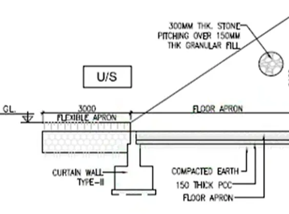
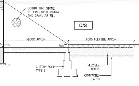
Protection works – The rigid flooring should be provided under the bridge and it should extend for a distance at least 3m on upstream and 5 m on downstream side of the bridge. However, in case the splayed wing walls of the structure are likely to be longer, the flooring should extend up to the line connecting the end of wing walls on either side of the bridge.
Flooring should consist of 150mm thick flat stone/brick on edge in cement mortar 1:3 laid over 300 mm thick cement concrete M15 grade laid over a layer of 150 mm thick cement concrete M10 grade. Joint at suitable spacing may be provided.
Curtain walls - The rigid flooring should be enclosed by curtain walls (tied to the wing walls) with a minimum depth below floor level of 2 m on upstream side and 2.5 m on downstream side. The curtain wall should be in cement concrete M15 grade or brick/stone masonry in cement mortar 1:3. The rigid flooring should be continued over the top width of curtain walls.
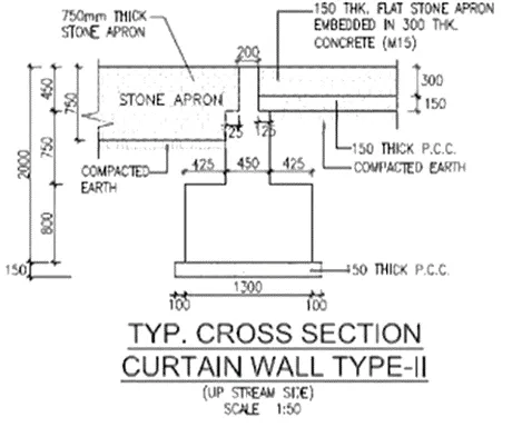
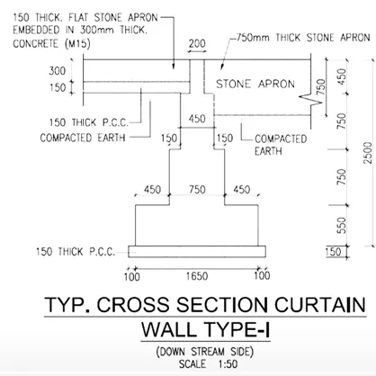
Flexible apron- Flexible apron 1 m thick comprising of loose stone boulders (weighing not less than 40 kg) should be provided beyond the curtain walls for a minimum distance of 3 m on upstream side and 6 m on downstream side. Where required size stones are not economically available, cement concrete blocks or stones in wire crates may be used in place of isolated stones.
__________________________________________________________________________________________
#1c.
Uplift can be defined as the upward pressure provide to the structure against the direction of gravity in such a way that has the potential to raise the structure from its intial position. It can be occurred due to increase of the pore water pressure within the soil resulting summation of those pressure lead to uplifts the structure.
IRC code, states that the upward pressure of water shall be taken as the full hydrostatic pressure applied over the entire area.
The structure must be designed properly to provide greater resistance against uplift forces in order to prevent risks due to water pressure. So, the uplift pressure must be taken into consideration during design stage since rehabilitation and maintenance of foundation cannot be carried out easily in the future.
Due to the uplift force structure tends to lose its stability and endangers to collapse. Due to the uplift force, the structure loses its anchorage with soil, which it maintained by the soil above the foundation, and tends differential positioning of foundation datum.
Prevention against uplift pressure
- Dewatering of the site before construction plays important role in it.
- Increasing the self-weight of structure.
- Provision of anchor bolts.
- Increase the depth of footing in order to increase the weight of soil above foundation
- Provision of deep foundation in order to achieve hard strata.
- Force due to Uplift –
(i)Fu = γw x H (for 3 m height)
γw = Unit weight of water = 10 KN/m3
H = Height = in meters (m)
Fu = 10 x 3 = 30 kN/m2
(ii) Fu = γw x H (for 4 m height)
Fu = 10 x 4 = 40 kN/m2
(iii) Fu = γw x H (for 5 m height)
Fu = 10 x 5 = 50 kN/m2
Measure to prevent uplift are mentioned below as follows:
Toeing in the Foundation into the Surrounding Ground
When a substructure is built inside an open excavation or temporary cofferdam, the base slab or raft foundation can be extended outside perimeter to increase resistance to uplift.
The weight of backfill material on the tied-in foundation increase the weight of the structure against uplift pressure. This method is not feasible where a diaphragm or secant pile wall is used as a permanent retaining structure.
Increase Self-weight of the Structure
The self-weight of the building can be increased by increasing the size of structural members. sometime, the dead weight of the low-rise podium in a high-rise complex is increased by incorporating a rooftop garden with a thick soil fill.
Ground Anchors
Pre-stressed anchors can be used as a temporary measure to counteract uplift forces. Permanent application of ground anchors is limited by concerns about their long-term performance with respect to corrosion.
Piling Method
The piling method is the most effective method to resist Uplift pressure. Various types of piles are available to be used for countering uplift pressure based on soil condition and their necessity on site.