Week 4 Challenge
Aim: To determine the earth pressure acting on abutment wall and analyze accordingly in Staad.Pro.
Introduction:
The objective is to calculate the earth pressure from backfill to retain the soil and pressure from soil ground level manually and attempt the same in Staad.Pro.
Earth Pressure is the horizontal thrust exerted by the retained soil on a vertical structural element either by gravity or surcharge force.
Unit weight of soil is defined as the ratio of total weight of soil mass (W) by the Total Volume of soil mass.
Unit Weight (γ) = Total weight of soil mass (W) / Total Volume of soil mass (V)
Active Earth pressure: - When the vertical structural member moves away from the backfill, the soil mass expands and there is a decrease in pressure.
Active Earth Pressure (Pa) = Coefficient of active earth pressure (Ka) x Unit weight of soil (W) x Height of soil (H)
Given Data (for calculation):
Height of Backfill soil from top of footing (H) = 7m
Height of Ground Level from top of footing (h) = 3m
Depth of footing = 1m
Level of water table at level of Ground level
Procedure:
Manual Calculations are to be made in order to provide the load intensity to the wall and recieve the analytical results.
Assumption:
Neglect the self-weight of structure into the calculation and staad model.
It is assumed that loads such as surcharge is not acting on wall.
It is assumed that height of wall above backfill is 1m above the backfill level.
Unit weight of backfill soil = 18 KN/m3
Submerged Unit Weight of Ground soil = 15 KN/m3 = γsat - γw
Coefficient of active earth pressure (Ka) = 0.35
Coefficient of earth pressure at rest (Ks) = 0.5
Junction between the ground soil & backfill is perfectly vertical.
Dimensions of footing are 4m x 7m.
Thickness of wall is 1m.
Allowable bearing capacity of soil is 200 KN/m2
Allowable settlement as per IS Code is 50 mm.
Factor of Safety = 1
Solution:
Earth pressure at the bottom of wall (Pb) due to backfill = Ka x γ x H = 0.35 x 18 x 7 = 44.1 KN/m2
Earth pressure at the bottom of wall (Pg) due to submerged soil = Ks x γs x h = 0.5 x 15 x 3 = 22.5 KN/m2
Earth pressure on the footing (Pbf) due to backfill = γ x H = 18 x 7 = 126 KN/m2
Earth pressure on the footing (Pgf) due to submerged soil = γs x h = 15 x 3 = 45 KN/m2
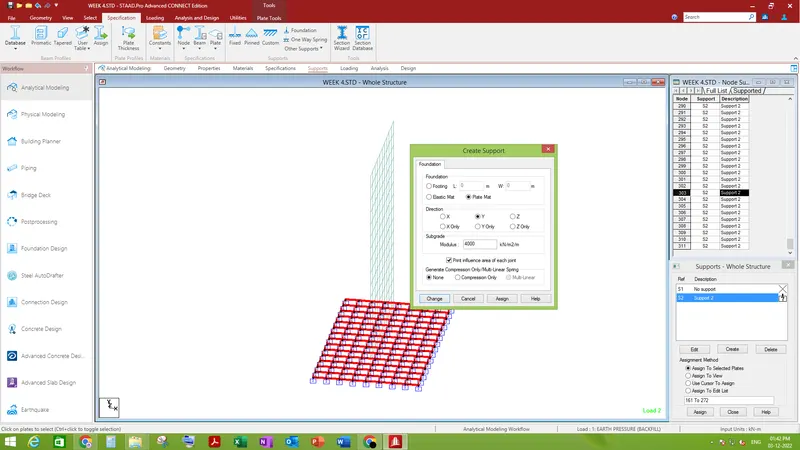
Soil Subgrade Modulus = Allowable Bearing Capacity x Factor of Safety/Allowable settlement = 200 x 1/0.05 = 4000 KN/m3
Computer Proficiency:
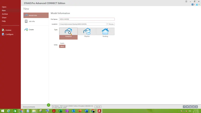
- Create a model by putting the necessary inputs as file location, units etc.
- Create two nodes (x,y,z) represents as (0,0,0) & (0,0.5,0). Because the mesh size of wall is 500mm x 500mm. and replicate the both nodes in the z direction by 0.5m.
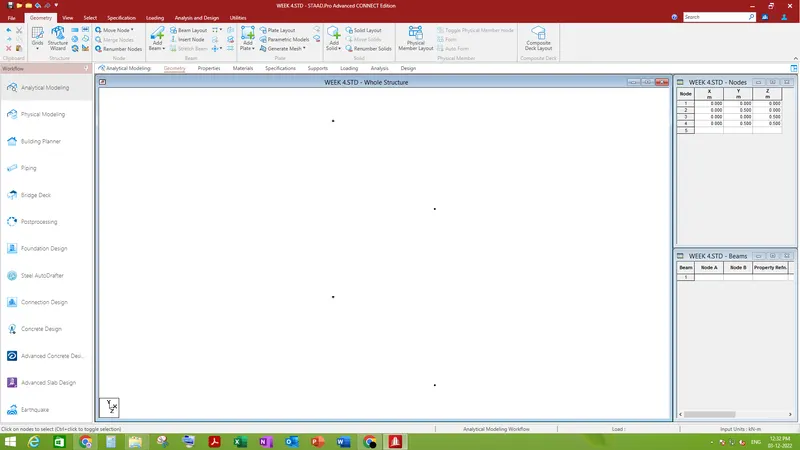
- Choose add plate cursor and connect all the nodes.
- Select the drawn plate and transitional repeat it to y direction at spacing of 0.5m and number of steps as 16. Because bottom mesh plate is to be ignored in loading as the footing depth is 1m.
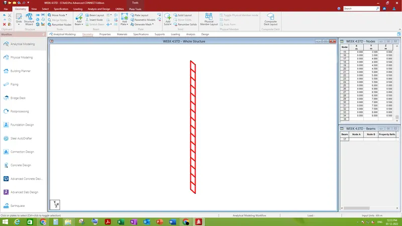
- And transitional repeat all the plates in z direction in 9 steps that makes the abutment wall.
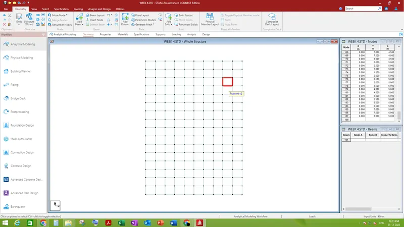
- Select all the bottom modes of wall and replicate them in x direction at spacing of 0.5m and accordingly makes the size of footing as 4m and 7m.
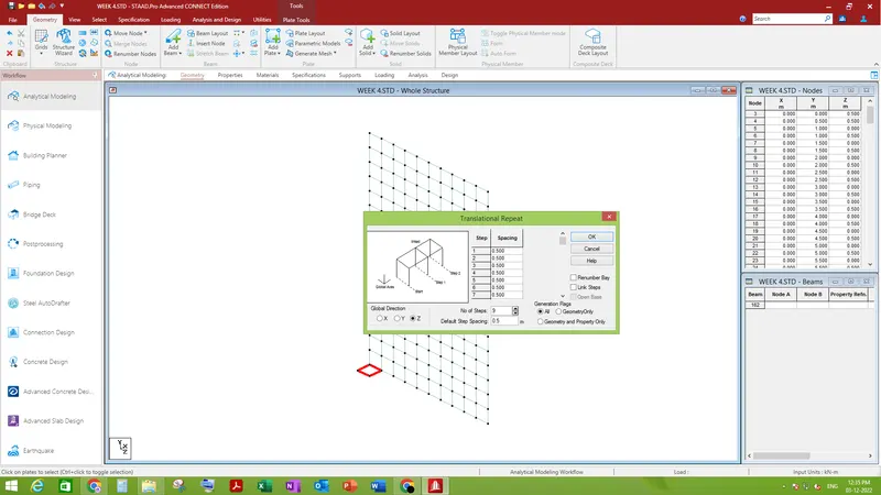
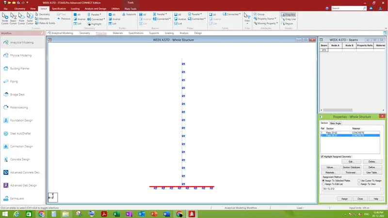
- And define the thickness of wall and footing as per assumption above and assign accordingly.
- As for supports, select supports and select foundation, choose plate mesh in y direction with the subgrade modulus calculated above. Assign to the bottom plates of footing.
- In order to assign the loads to the structure, different cases are taken into consideration as earth pressure due to backfill, earth pressure due to ground soil and earth pressure due to gravity.
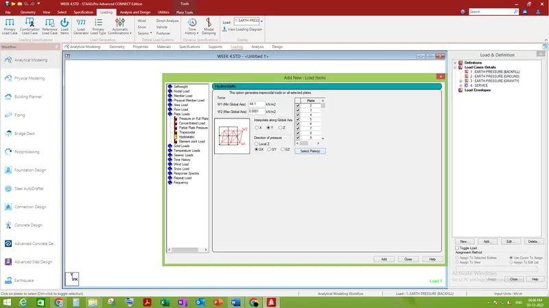
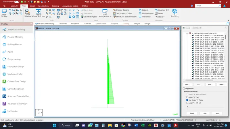
- As per Earth pressure due to backfill is provided in the form of hydrostatic force (Trapezoidal Force) as per above calculations but from the 0.5m height of the wall because the half that thickness will be occupied by footing after detailed study by interpolating in y direction and pressure in negative x direction and assign to the selected plates.
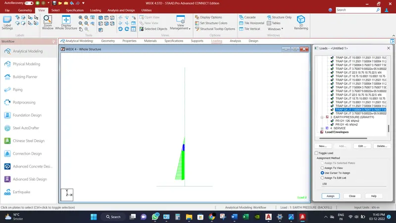
- Accordingly, earth pressure due to ground soil is assign to the wall in the same manner.
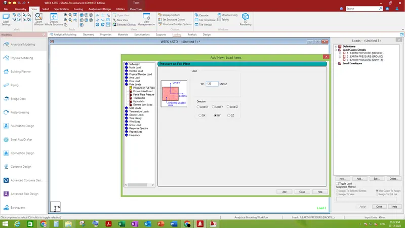
- Provide the earth pressure on the footing, accordingly to the above calculation by full plate load.
Analytical Results:
Wall has been analyzed and checked for different load cases and combinations and different displacements and reactions were found as mentioned below:
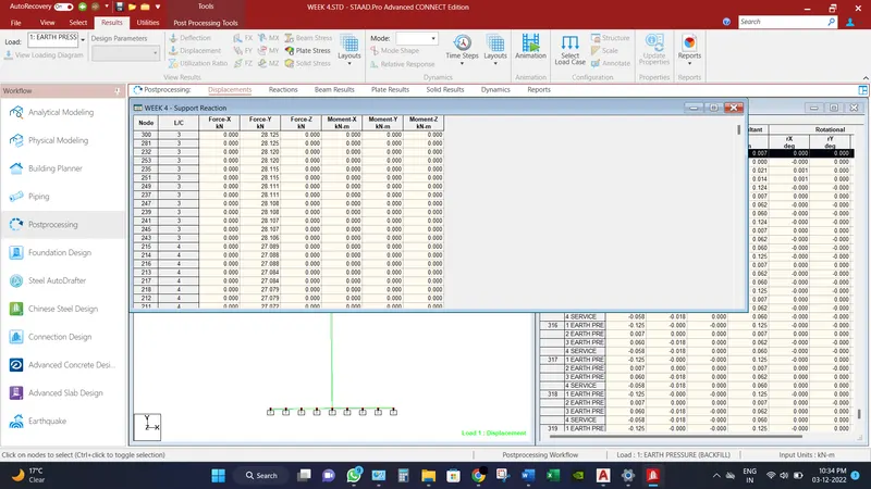
Maximum displacement has been recorded as 125mm.
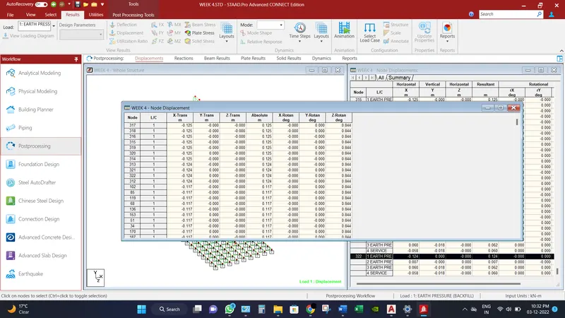
Maximum axial reactions are recorded as 28.125 KN.
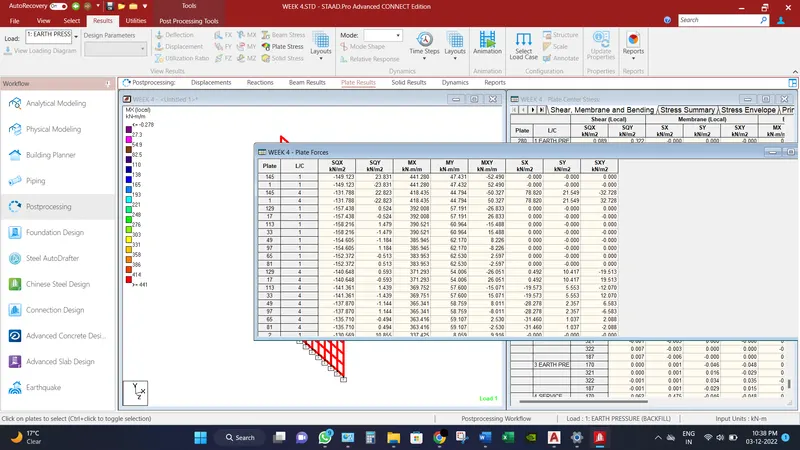
Maximum moment in Mx (local) direction is recorded as 441.28 KN-m/m.
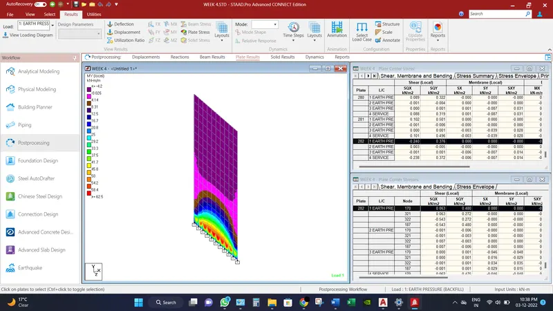
Maximum moment in My (local) direction is recorded as 62.5 KN-m/m.
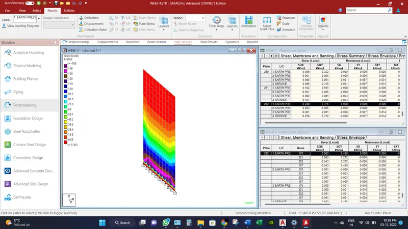
Maximum Shear in SQX (local) direction is recorded as 0.363 KN/m2.
Maximum Shear in SQY (local) direction is recorded as 23.8 KN/m2.
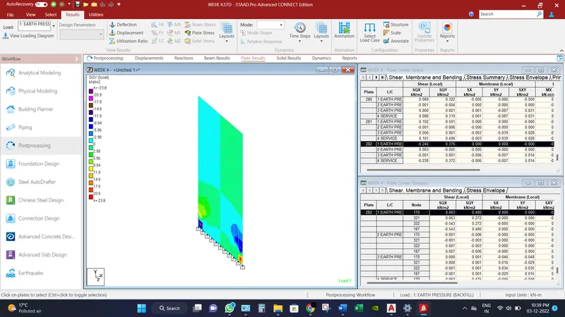
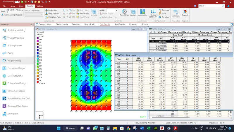
Maximum Shear in SQX (local) direction for footing slab is recorded as 174.682 KN/m2.
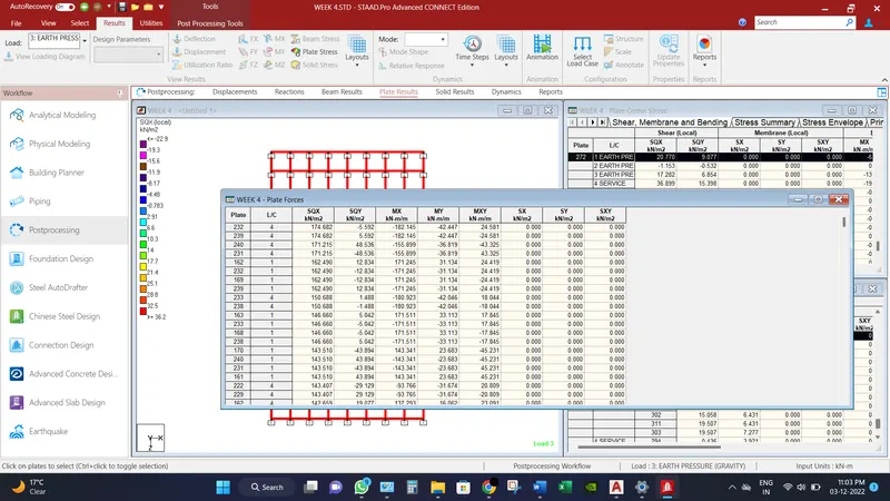
Maximum Shear in SQY (local) direction for footing slab is recorded as 86.147 KN/m2.
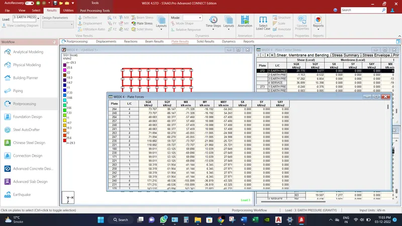
Maximum Moment in MX (local) direction for footing slab is recorded as 182.145 KN-m/m.
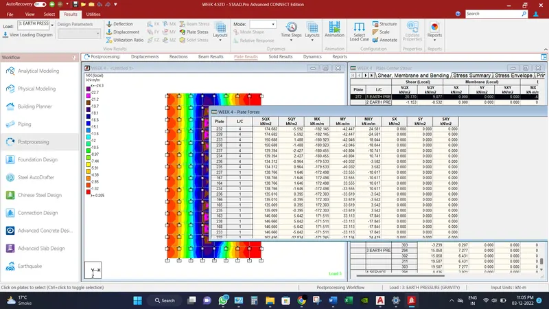
Maximum Moment in MY (local) direction for footing slab is recorded as 42.447 KN-m/m.
__________________________________________________________________________________________
Conclusion:
Maximum Moment in MY (local) direction for footing slab is recorded as 42.447 KN-m/m.
Maximum Moment in MX (local) direction for footing slab is recorded as 182.145 KN-m/m.
Maximum displacement has been recorded as 125mm.
Maximum axial reactions are recorded as 28.125 KN.
Maximum moment in Mx (local) direction is recorded as 441.28 KN-m/m.
Maximum moment in My (local) direction is recorded as 62.5 KN-m/m.
Maximum Shear in SQX (local) direction is recorded as 0.363 KN/m2.
Maximum Shear in SQY (local) direction is recorded as 23.8 KN/m2.
Maximum Shear in SQX (local) direction for footing slab is recorded as 174.682 KN/m2.
Maximum Shear in SQY (local) direction for footing slab is recorded as 86.147 KN/m2.